Page is loading ...


4
Warranty Information
Equipment manufactured by Surna (“Company”),
the warranty shall exist for a period of twelve (12)
months from initial start-up or 18 months from date of
shipment, whichever period is shorter, against failure
due to defects in material and / or manufacturing and
warranted to the capacities and ratings set forth in
Company’s catalogs and bulletins (“Warranty”).
Equipment, material, and or parts that are not
manufactured by Company are not warranted by
Company and carry such warranties as may be
extended by the respective manufacturer.
Exclusions from this Warranty include damage or
failure arising from: wear and tear; corrosion, erosion,
deterioration; modications made by others to the
Equipment; repairs or alterations by a party other than
Company that adversely affects the stability or reliability
of the Equipment; vandalism; neglect; accident;
adverse weather or environmental conditions; abuse
or improper use; improper installation; commissioning
by a party other than Company; unusual physical or
electrical or mechanical stress; lack of proper start-
up or maintenance as recommended by Company;
operation with any accessory, equipment or part not
specicallyapprovedbyCompany;andorrefrigerant
not recommended or supplied by Company.
Company shall not be obligated to pay for the cost
of lost refrigerant or lost product or any other direct,
indirect, or consequential damages. Company’s
obligations and liabilities under this Warranty are
limited to furnishing replacement equipment or
parts, at its option, FCA (Incoterms 2000) factory
or warehouse (f.o.b. factory or warehouse for US
domestic purposes) at Company-designated shipping
point, freight-allowed to Company’s warranty agent’s
stock location, for all non-conforming Company-
manufactured Equipment which have been returned
by Customer to Company.
Returns must have prior written approval by Company
and are subject to restocking and replacement charges
where applicable.
No warranty liability whatsoever shall attach to
Company until Customer’s complete order has been
paid for in full and Company’s liability under this
Warranty shall be limited to the purchase price of the
Equipment shown to be defective.
Additional warranty and service protection is available
on an extra-cost basis and must be in writing and
agreed to by an authorized signatory of the Company.
The warranty excludes: (a) labor, transportation and
related costs incurred by the Dealer or Customer;
(b) re-installation costs of repaired equipment; (c)
re-installation costs of replacement equipment;
(d) removal costs of equipment; (e) consequential
damages of any kind; and, (f) reimbursement for loss
caused by interruption of service.
EQUIPMENT MANUFACTURED BY COMPANY THAT
INCLUDES A REQUIRED START-UP AND SOLD IN
NORTH AMERICA WILL NOT BE WARRANTED BY
COMPANY UNLESS COMPANY OR ITS AUTHORIZED
AGENT PERFORMS THE EQUIPMENT STARTUP.
COMPANY MAKES NO REPRESENTATION OR
WARRANTY, EXPRESS OR IMPLIED, REGARDING
PREVENTION OF MOLD/MOULD, FUNGUS,
BACTERIA, MICROBIAL GROWTH, OR ANY OTHER
CONTAMINATES.
EXCEPT FOR COMPANY’S WARRANTY EXPRESSLY
SET FORTH HEREIN, COMPANY DOES NOT
MAKE, AND HEREBY EXPRESSLY DISCLAIMS,
ANY WARRANTIES, EXPRESS OR IMPLIED
CONCERNING ITS PRODUCTS, EQUIPMENT OR
SERVICES, INCLUDING, WITHOUT LIMITATION, ANY
WARRANTY OF DESIGN, MERCHANTABILITY OR OF
FITNESS FOR A PARTICULAR PURPOSE, OR OTHERS
THAT ARE ALLEGED TO ARISE FROM COURSE OF
DEALING OR TRADE.

5
Below is a list of all parts provided with each
SurnaDehumidier.
Dehumidier Parts
1.SurnaDehumidier
2.SurnaDehumidierProductManual
3. Dehumidistat
4. 15 ft of Thermostat Wire
5. PVC Condensate Trap
The Surna Dehumidier is intended to operate in
temperatures between 74 - 86 degrees F and a relative
humidity of 40% or higher.
To ensure effective humidity control, the location
wheretheSurnaDehumidierisoperatedmustbefree
ofwaterintrusionandoutsideairinltration.Priorto
installation,waterintrusionandoutsideairinltration
issues need to be addressed in the facility.
NOTE: Depending on room height, temperatures and
relative humidity levels at canopy level may differ from
theDehumidiermountingposition.Inthiscase,itis
recommended to implement a form of air mixing or air
destraticationfans.
CAUTION: Surna Dehumidiers are not designed to
operate in temperatures below 65 degrees F. If the
Dehumidierisoperatedbelow65degreesF,theunit
can frost up. Permanent damage may occur.
If frosting is suspected, shift the position of the unit or
circulating fans so that warmer air is circulated around
the dehumidier unit. A small blower or heater can
alsobeaimedatthedehumidierunit.Ifthisstopsthe
frosting, consider raising the temperature of the room
above 65 degrees F.
Intended Application

6
Warnings
Safety Symbols Used
Dehumidier Safety Guide
Please read the information in this document carefully
prior to attempting the installation, operation
and/or servicing of the dehumidier unit. This
document contains all information required to install
and operate the Surna dehumidifying device. Failure
to follow the directions provided could cause damage
to the dehumidier equipment and/or accessory
equipment, damage to building facilities, and/or
serious injury or death to the operator. Please adhere
to all applicable safety guideline requirements in this
document and all applicable electrical and mechanical
jurisdictional codes. Using Surna dehumidifying
equipment in a manner not described in this manual
may void unit warranty.
CAUTION: Important information, read the
provided instructions carefully.
WARNING: Potential electric shock hazard.
WARNING: High voltage
WARNING: Cut / Crush hazard Prior to providing power to the equipment, be sure
to inspect the area for water spills, which may present
a shock hazard to the user. Take extra care to mount
accessory electrical equipment away from areas
regularly exposed to water. Be sure to provide secure
wire and cable routing to protect personnel from shock
hazards.
Consult with a licensed electrician before attempting
electrical installation. DO NOT operate the unit
outside specied operating parameters as given
in the Intended Application section. Only operate
the equipment with an appropriately sized switch or
circuit breaker in place. Only operate equipment with
adequate wire sizes and current carrying capacity. The
switch or circuit breaker shall be accessible without the
use of a tool, shall be easily accessible to users, shall
be clearly marked with “ON” and “OFF” positions,
and shall disconnect all current carrying conductors
simultaneously.
Protective Earth connection
Action prohibited
Denitions
CAUTION: Risk of minor/moderate injury if precaution
not taken.
WARNING: Risk of death/serious injury if warning isn’t
heeded.
DANGER: Risk of death/serious injury if danger isn’t
avoided.

7
The power supply cord contains a ground fault circuit
interrupter (GFCI) that senses damage to the power
cord. To test your power supply cord do the following:
1.PlugintheSurnaDehumidier.
2. The plug head has two buttons
TEST/RESET. Press the TEST button and the
RESET button will pop out.
3. Press the RESET button and the TEST
button disengages.
4. The power supply cord is now supplying
electricity to the unit. Power is indicated
by a green light on the plug head.
DO NOT use extension cords or plug adapters. These
actionsmayresultinarehazardorelectricshock.
This unit must be connected to a protective Earthing
system prior to operation. DO NOT remove the
grounded connection while power is being supplied to
theSurnaDehumidier.Doingsopresentsanelectric
shock hazard to users and service personnel.
This device is intended for indoor use only and should
beprotectedfromrainandooding.
This equipment is not meant for connection to a
ducting system.
Onlyusepartsprovidedwith,orspeciedforuseinthis
document for use with the dehumidier equipment,
installation, and servicing.
Care must be taken when handling sheet metal. Sheet
metal parts have sharp edges and could cause serious
bodily injury.
The components of this unit have been inspected at
the factory and readied for shipment. Upon receiving
the shipment a visual inspection of the packaging must
be performed. Any shipping damage must be noted
at time of delivery.
DO NOT use this unit as a bench or table.
DO NOT operate this unit with a damaged power
cord. If the power cord is damaged it must be replaced
by the manufacturer or a qualied/licensed service
technician.
Priortoinstallingthedehumidier,applypowertothe
unit and verify the fan and compressor are operating
normally.

8
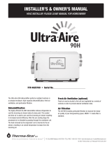
Technical Description
TheSurnaDehumidierusesarefrigerationsystemcycletoremoveheatandmoisturefromtheenvironment.
Low-pressurerefrigerantgasiscompressedinthecompressorandowstothecondensercoil.Therefrigerant
is condensed to a liquid and gives off heat to the outside air. The refrigerant pressure and temperature are
reduced by passing through a series of capillary tubes which act like an expansion valve. Refrigerant then
owstotheevaporatorcoil.Theevaporatorcoiliswhereheatistransferredfromtheincomingairtotheliquid
refrigerant causing it to evaporate. This is the point in which moisture condenses out of the humid air through
condensation.Next,refrigerantowsfromtheevaporatortotheaccumulator,enteringtheaccumulatorasa
mixture of liquid and gas. The accumulator prevents liquid refrigerant from entering the compressor, boiling off
liquid so that only hot, low pressure gas enters the compressor and the cycle begins again.
Figure1-DehumidierRefrigerationSystemOverview

9
Specications
Model Number
• SCMDH-300
Dimensions
• Length: 25.4”
• Width: 26”
• Height: 17.3”
• Weight: 132 lbs
Operating Characteristics
• Nominal Capacity: 25,000 BTU/hr
• NominalDehumidication:300pints/day
• Fan Motor: 150W
• FanAirow:560SCFM
Electrical Data
• Voltage/Phase: 208/230 Single Phase
• Nominal Current Draw: 12.8A/12.0A
• Maximum Overcurrent: 20A
• PowerFactor:0.99
Condensate Connection
• Drain: 3/4” NPT
• ElectrostaticAirFilter:11.69”x22.25”x1”
Cooling System
• Refrigerant Type: R410A
• Refrigerant Charge: As Labeled
Water Removal Rate*
• Environment: 80 Degrees F / 60% RH
• Pints per Day: 263.46
• Energy Factor: 2.187 L/kWh
• Environment: 80 Degrees F / 80% RH
• Pints per Day: 348.81
• Energy Factor: 2.654 L/kWh
*Veried by third party testing.
NOTE: This unit is to be powered through a standard
230VAC, 20A circuit via supplied power cord only.

10
Mounting details and information are summarized in
Figures 2-6.
The Surna Dehumidier is designed for overhead
mounting within the space that requires conditioning.
Priortomounting,conrmthatthesupportingsurface
and mounting means are suitably rated for the
dehumidierweightload(seeSpecicationssectionof
this document). When mounting, care must be taken
to slope the unit 5 degrees towards the condensate
drain port. This slope has been built into the mounting
bracket positioning. Simply verify that the top of the
mounting brackets are leveled with respect to one
another to ensure proper drainage.
The Surna Dehumidier requires a minimum of 12”
vertical clearance above the unit when hanging.
This unit requires a minimum of 24” (recommended
72”) of clearance on the air intake and exhaust
sides when placed next to walls or structures. When
placed next to Air Handlers, fans, or cooling units,
theSurnaDehumidierrequires3’ofclearanceonthe
air intake and exhaust sides. DO NOT position the
SurnaDehumidierairintake/exhaustin-linewithcold
air exhaust from other air handling or cooling units/
circulatory fans. Improper positioning will decrease
unitefciencyandcouldcausedamagetotheunit.
This unit includes a plug and power cord with GFCI built
in, and should be plugged into a dedicated outlet. DO
NOTuseanextensioncord.ReadtheSpecications
section of this document for more information on the
power and circuit breaker requirements.
An On/Off switch located on the front face of the unit
is used to provide power to the equipment. The fan in
the unit will run with the switch in the “OFF” position,
but the compressor will not run while the switch is in
the “OFF” position. The On/Off switch should be
switched to “ON” to begin normal operation. An
external switch or circuit breaker shall be used as the
primary disconnect device. The disconnect device
shall be accessible to users, have a clearly marked On/
Off position and must disconnect all current carrying
conductors simultaneously.
A humidity controller is provided with the Surna
Dehumidier.Tousethisfeatureofthedehumidier,
install the switch wire in the provided connector block
and make the connection to the mating end attached
to the exterior of the unit.
Mechanical Electrical
Condensate drains should be connected to a waste or
reclamation system in order to direct the condensate
out of the space. Ensure condensate lines remain
unobstructed to avoid unattended spillage or drain
panoverow. Useof ap-trap (referenceFigure2) is
recommended to avoid pressure and vacuum related
issues, which can negatively affect condensate
drainage. Following plumbing installation, the system
should be checked for leaks prior to attempting
unattended operation. It is recommended to insulate
the drain line in order to prevent condensation build
up on the drain.
Plumbing
Installation Instructions

11
Figure 2 - Installation Diagram
Figure 2 shows proper mounting of the Surna Dehumidier, with required clearances and recommended
condensate trap.
5°
slope
Level
Mounting
Surface
Drain
Pan
Vent
Mounting
Brackets
P
Trap
Drain
Airflow
In
Airflow
Out
Ceiling
-
12”
min.
clearance
Exhaust
-
min.
24”
Clearance
Air
Intake
-
min.
24”
Clearance

12
Figure3showsproperclearancesfortheSurnaDehumidier.
Figure 3 - Required Minimum Clearances
B
1
reifidimuheD anruS1
2Do not block intake or discharge
3Do not direct any air into intake or discharge via fans or
vents
4
No conditioned air discharge or circulating fans within min 3
feet (recommended 72 inches) from intake or discharge of
unit
2
4
woleb dna evoba ecnaraelc fo sehcni 21 niMA
BMin clearance of 24 inches (recommended 72 inches) from
any wall or structure in front of intake or discharge
A
FLOW FLOW
3
WOLFWOLF
REQUIRED
UNIT CLEARANCES
A: Min. 12” of clearance above and below unit
B: Min. 24” (recommended 72”) of clearance from any wall or structure in front of intake or
discharge
1:SurnaDehumidier
2: Do not block intake or discharge
3: Do not direct any air into intake or discharge via fans or vents
4: No conditioned air discharge or circulating fans within minimum 3’ (recommended 72”)
from intake or discharge of unit

13
Figure4showsproperpositioningofyourSurnaDehumidierwithregardtoairow.
Figure4-ProperUnitAirow
reifidimuheD anruS1
reldnaH riA anruS2
3No conditioned air discharge or circulating fans within 3 feet
from intake or discharge of unit
4Units may disregard "3" if intakes are opposing and a min
24 inches (recommended 72 inches)
5DO NOT exhaust into units intake or exhaust
woleb dna evoba ecnaraelc fo sehcni 21 niMA
BMin 24 inches (recommended 72 inches) between 2 units
with adjacent intakes
FLOW FLOWFLOW FLOW
B
4
FLOW FLOW
5
1 or 2
3
A
PROPER
UNIT AIRFLOW
A: Min. 12” of clearance above and below unit
B: Min. 24” (recommended 72”) of clearance between two units with adjacent intakes
1:SurnaDehumidier
2: Surna Air Handler
3: No conditioned air discharge or circulating fans within minimum 3’ (recommended
72”) from intake or discharge of unit
4: Units may disregard number 3 if intakes are opposing and have a clearance minimum
of 24” (recommended 72”)
5. DO NOT exhaust into unit’s intake or exhaust

14
Figure5illustratescorrectoperationaloffsetsfortheSurnaDehumidieriflinearspaceislimitedintheroomto
provideproperunitandairowclearancesbetweenunits.
Figure 5 - Proper Vertical Offset
1 or 2
reifidimuheD anruS1
reldnaH riA anruS2
3No conditioned air discharge or circulating fans within 3 feet
(recommended 72 inches) from intake or discharge of unit
AMin 12 inches of clearance above and below
FLOW
FLOW
FLOW
FLOW
FLOW FLOW
A
A
3
REQUIRED
UNIT OFFSETS
A: Min. 12” of clearance above and below unit
1:SurnaDehumidier
2: Surna Air Handler
3: No conditioned air discharge or circulating fans within minimum 3’ (recommended
72”) from intake or discharge of unit

15
Figure 6 provides a Bird’s Eye View of proper installation of the Surna Dehumidier, with recommended
clearances.
Figure 6 - Bird’s Eye View of Clearances
1 Surna Dehumidifier
2 Surna Air Handler
3Oppose flow by 90 degrees for neighboring units
4
No conditioned air discharge or circulating fans within 3 feet
min (recommended 72 inches) from intake or discharge of
unit
AMin 24 inches (recommended 72 inches)
FLOW FLOW
A
A
FLO
W
1
BIRD'S EYE UNIT CLEARANCES
A: Min. 12” of clearance above and below unit
1:SurnaDehumidier
2: Surna Air Handler
3:Opposeowby90degreesforneighboringunits
4: No conditioned air discharge or circulating fans within minimum 3’
(recommended 72”) from intake or discharge of unit

16
Normal Operation
Tostartnormaloperation,iptheswitchonthefrontoftheunittothe“ON”positionandsettheprovided
humidity controller to the desired setting for the space.
Figure 7 - Installation Connections
Mounting Brackets
Dehumidistat Switch
Connector ON/OFF Toggle
Switch
Filter Set Screw
Power Cord
Condensate Drain

17
Routine Maintenance
This product is designed to provide many years of
dependable, trouble free operation when properly
maintained. Failure to provide periodic check-ups and
cleaning can result in excessive operation cost and/
or equipment failure. Required routine maintenance
consistsofcoilcleaning,ltercleaning/changing,and
condensate drain inspection/cleaning.
WARNING: Before performing any maintenance or
servicing, verify unit is disconnected from power
source.ServicingtheSurnaDehumidier,withitshigh
pressure refrigerant system, high voltage circuitry,
and internal fan, presents a health hazard which could
result in death, serious bodily injury, and/or property
damage. DO NOT attempt maintenance or repairs
unless you are properly trained to do so.
Evaporator and condenser coils can be vacuumed out.
To access the evaporator coil remove set screw and
removelter.Usecautionwhencleaningthecoils.The
coilnsaresharpandmaycauseinjuryifimproperly
handled.Thecoilnsareextremelydelicateandcan
bedamagedeasily.Damagedcoilsnscanreduceair
owandnegativelyaffecttheperformanceoftheunit.
DO NOT use coil cleaner that is designed for outdoor
coils, as it may be corrosive.
The Surna Dehumidier comes equipped with an
electrostaticlter.Ifproperlymaintained,electrostatic
lters will provide long lasting ltration. It is
recommendedtocleanthe lter every30days,ata
minimum. (Depending on media used i.e. coco may
require more frequent cleanings.) Operating the unit
with a dirty lter will reduce dehumidier capacity
and efciency and may cause the compressor to
unnecessarily cycle on and off. DO NOT operate the
unitwithoutthelter.
1. Removeltersetscrew.
2. Removelter.
a. Ifthelterisrippedorphysically
damaged, it should be replaced.
3. Checklterforcleanliness.
a. Holdlteruptolightsource,and
check for transparency.
i. The more light showing through,
thecleanerthelter.
ii.Iflightcannotbeseen,thelter
needs to be cleaned.
4. Theltercanbevacuumedoutorwashed
with water.
a. Whenwashingthelterwithwater,
spraywaterthroughthelterinthe
oppositedirectionoftheairow
indicator.
b. Whenvacuumingthelter,ensure
that the vacuum is pulling dirt and
debrisfromthelterintheopposite
directionoftheairowindicator.This
will push dust and debris out of the
lterinsteadofintothelter.
c. Airowisindicatedbyadirectional
arrowonthesideofthelter.
5. Spraythelterwithmilddetergent(onlyif
washing with water). (optional)
a. When done cleaning, it should be
possible to see light showing through
thelter.
b.Ifitisnotpossibletocleanthelter
to the point where light is able to shine
through,theltershouldbereplaced.
6. Letlterairdryforatleast10minutes.The
ltercanbeuseddamp,butnotdrippingwet.
a. Ensuredrainholesonthelterare
facing down for proper drainage and
drying.
7. Reinstallthelterwiththeairowindicator
pointing in, toward the evaporator coil.
Cleaning the Filter

18
Troubleshooting
Prior to calling Surna technical support, follow these
troubleshooting steps. While steps 1-6 may be handled
byanyonewithbasicknowledgeofthedehumidier
set up, steps 7-12 should be handled by a trained
technician.
To avoid voiding the warranty, please contact Surna
via email at [email protected] or via phone at
303.993.5271x127beforehavingatechnicianperform
work.
Customer
1. Verify the unit is plugged in and GFCI is not tripped.
2. Verify power to outlet is on.
3. Ensure circuit breaker has not tripped.
4. Verifytoggleswitchlocatedonthedehumidieris
in the “ON” position. (Fan will constantly run even
if the toggle switch is in the “OFF” position.)
5. Verifythatlterandevaporatorcoilareclean.(See
Routine Maintenance section of this document.)
6. Verify the Humidistat is set to “ON” and ensure
the thermostat is connected securely.
Technician
NOTE:TheSurnaDehumidierisintendedtooperate
in temperatures between 74 -86 degrees F and a
relative humidity of 40% or higher.
NOTE: Temperatures and relative humidity levels at
canopy level may differ from the ceiling environment
(dehumidier mounting position). In this case, it is
recommended to implement a form of air mixing or air
destraticationfans.
NOTE: Periodic visual inspection of the condensate
drain is recommended. If signs of leaks or corrosion
exist, such as corrosion or water stains on the oor,
notifySurnatechnicalsupportat303.993.5271x127
If steps 1-6 are unsuccessful, contact Surna Technical
Support at 303.993.5271 x127 before calling a
technician.
7. Check that air is being pulled through the
evaporator coil and pushed out the condenser coil.
8. Checkthatthelterandevaporatorcoilontheunit
are clean. If not, clean these items with water.
9.Check condensate plumbing. Installation of
P-traps on all dehumidier condensate drains
is recommended. Condensate drains should be
sloped downward to a waste or reclamation system
in order to direct the condensate out of the space
If steps 11-12 are unsuccessful, contact Surna at
303.993.5271x127forfurtherinstructionsontesting
environmental conditions and/or unit refrigerant
charge.
If steps 7-10 are unsuccessful, remove dehumidier
from ceiling and remove top cover. (Technician only)
10.Checkplacementangleofdehumidierunit.Unit
should be angled approximately 5 degrees
towards condensate drains. If the angle is out of
spec, correcting the slope is recommended.
11. Check internal temperature controller (Ranco)
withintheunit,contactSurnaat303.993.5271
x127 for detailed Ranco troubleshooting
instructions. Verify that the Ranco set point is
32 degrees F.
12. Check temperature probe. Verify the probe is fully
inserted into the evaporator coil for accurate
temperature readings. If installed correctly, the
temperature probe should not be visible.

19
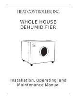
Wiring Diagram
Figure 8 - Wiring Diagram
TOGGLE
SWITCH
Supplied 230 VAC
Plug/Power Cord
CONTACTOR
TRANSFORMER
208 / 230 VAC
24 VAC
DELAY RELAY
HUMIDITY
CONTROL
FAN MOTOR
COMPRESSOR
CAP
FAN RELAY
COMPRESSOR
RANCO
TEMP
CONTROL
RED
YELLOW
BLUE
BLK
WHITE
RED
BLUE
BLK
RED
BLUE
LINE
NEUTRAL
WHITE (COM)
ORANGE (240 VAC) RED (24 VAC)
BLUEBLUE
BLUE
BLK
GREEN
SCHEMATIC DIAGRAM: SCMDH-300
RED
+_
BLK
WHITE

/