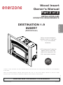
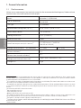
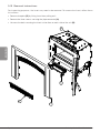
The Enerzone EB00066 is a Destination 1.9 Insert that offers up to 31,700 BTU/h of heating capacity, burning dry cordwood logs up to 17 inches long. Featuring an included blower, this wood insert is designed to provide efficient heat distribution and optimal comfort. It boasts an average overall efficiency of 75% and a maximum burn time of 7 hours, making it a dependable heating solution for larger spaces up to 1,200 sq. ft.
The Enerzone EB00066 is a Destination 1.9 Insert that offers up to 31,700 BTU/h of heating capacity, burning dry cordwood logs up to 17 inches long. Featuring an included blower, this wood insert is designed to provide efficient heat distribution and optimal comfort. It boasts an average overall efficiency of 75% and a maximum burn time of 7 hours, making it a dependable heating solution for larger spaces up to 1,200 sq. ft.


-
 1
1
-
 2
2
-
 3
3
-
 4
4
-
 5
5
-
 6
6
-
 7
7
-
 8
8
-
 9
9
-
 10
10
-
 11
11
-
 12
12
-
 13
13
-
 14
14
-
 15
15
-
 16
16
-
 17
17
-
 18
18
-
 19
19
-
 20
20
-
 21
21
-
 22
22
-
 23
23
-
 24
24
-
 25
25
-
 26
26
-
 27
27
-
 28
28
-
 29
29
-
 30
30
-
 31
31
-
 32
32
-
 33
33
-
 34
34
-
 35
35
-
 36
36
-
 37
37
-
 38
38
-
 39
39
-
 40
40


The Enerzone EB00066 is a Destination 1.9 Insert that offers up to 31,700 BTU/h of heating capacity, burning dry cordwood logs up to 17 inches long. Featuring an included blower, this wood insert is designed to provide efficient heat distribution and optimal comfort. It boasts an average overall efficiency of 75% and a maximum burn time of 7 hours, making it a dependable heating solution for larger spaces up to 1,200 sq. ft.
Ask a question and I''ll find the answer in the document
Finding information in a document is now easier with AI
Related papers
-
Enerzone EB00057 Owner's manual
-
-
-
-
-
-
-
-
-
Other documents
-
Century CB00027 Owner's manual
-
 Drolet ESCAPE 1500-I Owner's manual
-
Osburn OB01705 Owner's manual
-
 Drolet ESCAPE 1500-I WOOD INSERT TRIO Owner's manual
-
 SBI AC01216 Installation guide
-
-
Century CW2900-I + FACEPLATE Owner's manual
-
-
Empire SF00613 Gateway 2300 Stove Archway 2300 Insert User manual
-
 Drolet CAPE TOWN 1800 CAST IRON WOOD STOVE Owner's manual


