BLAUBERG Blaubox EC ME User manual
- Category
- Split-system air conditioners
- Type
- User manual

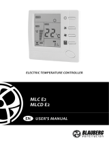
Single-block air Supply unit
USER’S MANUAL
EN
BLAUBOX EC ME 300 S30/31/32
BLAUBOX EC ME 400 S30/31/32
BLAUBOX EC ME 700 S30/31/32
BLAUBOX EC ME 1000 S30/31/32
BLAUBOX EC ME 1500 S30/31/32
BLAUBOX EC ME 2000 S30/31/32
BLAUBOX EC ME 3000 S30/31/32
BLAUBOX EC ME 4000 S30/31/32

www.blaubergventilatoren.de blauboX ec Me 300/400/700/1000/1500/2000/3000/4000 S30/31/32
2
Safety requirements ..................................................................................................................................................................... 3
Purpose ................................................................................................................................................................................................ 5
Delivery set ........................................................................................................................................................................................ 5
Designation key .............................................................................................................................................................................. 5
Technical data .................................................................................................................................................................................. 6
Design and operating principle ........................................................................................................................................... 9
Mounting and set-up .................................................................................................................................................................. 13
Connection to power mains .................................................................................................................................................. 15
Technical maintenance .............................................................................................................................................................. 21
Troubleshooting ............................................................................................................................................................................. 22
Storage and transportation regulations .......................................................................................................................... 22
Manufacturer’s warranty ........................................................................................................................................................... 23
Certificate of acceptance .......................................................................................................................................................... 27
Seller information .......................................................................................................................................................................... 27
Installation certificate .................................................................................................................................................................. 27
Warranty card ................................................................................................................................................................................... 27
CONTENTS
This user’s manual is a main operating document intended for technical, maintenance, and operating staff.
The manual contains information about purpose, technical details, operating principle, design, and installation of the
BLAUBOX EC ME 300/400/700/1000/1500/2000/3000/4000 S30/31/32 unit and all its modifications.
Technical and maintenance staff must have theoretical and practical training in the field of ventilation systems and should be able to
work in accordance with workplace safety rules as well as construction norms and standards applicable in the territory of the country.

www.blaubergventilatoren.de
blauboX ec Me 300/400/700/1000/1500/2000/3000/4000 S30/31/32
3
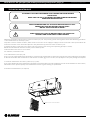
SAFETY REQUIREMENTS
Connection to the mains must be made through a disconnecting device, which is integrated
into the fixed wiring system in accordance with the wiring rules for design of electrical units,
and has a contact separation in all poles that allows for full disconnection under overvoltage
category III conditions.
If the supply cord is damaged, it must be replaced by the manufacturer, its service agent, or
similarly qualified persons in order to avoid a safety hazard.
Ensure that the unit is switched off from the supply mains before removing the guard.
WARNING: If there are any unusual oscillating movements, immediately stop using the unit and
contact the manufacturer, its service agent or suitably qualified persons.
The replacement of parts of the safety suspension system device shall be performed by the
manufacturer, its service agent or suitably qualified persons.
CAUTION: In order to avoid a safety hazard due to inadvertent resetting of the thermal cut-
out, this unit must not be supplied through an external switching device, such as a timer, or
connected to a circuit that is regularly switched on and off by the utility.
Precautions must be taken to avoid the back-flow of gases into the room from the open flue of
gas or other fuel-burning appliances.
The appliance may adversely affect the safe operation of appliances burning gas or other
fuels (including those in other rooms) due to back flow of combustion gases. These gases can
potentially result in carbon monoxide poisoning. After installation of the unit the operation
of flued gas appliances should be tested by a competent person to ensure that back flow of
combustion gases does not occur.
This unit is not intended for use by persons (including children) with reduced physical, sensory
or mental capabilities, or lack of experience and knowledge, unless they have been given
supervision or instruction concerning use of the unit by a person responsible for their safety.
Children should be supervised to ensure that they do not play with the unit.
This appliance can be used by children aged from 8 years and above and persons with reduced
physical, sensory or mental capabilities or lack of experience and knowledge if they have been
given supervision or instruction concerning use of the appliance in a safe way and understand
the hazards involved.
Cleaning and user maintenance shall not be made by children without supervision.
Children shall not play with the appliance.
This appliance incorporates an earth connection for functional purposes.

www.blaubergventilatoren.de blauboX ec Me 300/400/700/1000/1500/2000/3000/4000 S30/31/32
4
THE PRODUCT MUST BE DISPOSED SEPARATELY AT THE END OF ITS SERVICE LIFE.
DO NOT DISPOSE THE UNIT AS UNSORTED DOMESTIC WASTE
All operations described in this manual must be performed by qualified personnel only, properly
trained and qualified to install, make electrical connections and maintain ventilation units.
Do not attempt to install the product, connect it to the mains, or perform maintenance yourself.
This is unsafe and impossible without special knowledge.
Disconnect the power supply prior to any operations with the unit.
All user’s manual requirements as well as the provisions of all the applicable local and national
construction, electrical, and technical norms and standards must be observed when installing
and operating the unit.
Disconnect the unit from the power supply prior to any connection, servicing, maintenance, and
repair operations.
Connection of the unit to power mains is allowed by a qualified electrician with a work permit
for the electric units up to 1000 V after careful reading of the present user’s manual.
Check the unit for any visible damage of the impeller, the casing, and the grille before starting
installation. The casing internals must be free of any foreign objects that can damage the
impeller blades.
While mounting the unit, avoid compression of the casing! Deformation of the casing may result
in motor jam and excessive noise.
Misuse of the unit and any unauthorised modifications are not allowed.
Do not expose the unit to adverse atmospheric agents (rain, sun, etc.).
Transported air must not contain any dust or other solid impurities, sticky substances, or fibrous
materials.
Do not use the unit in a hazardous or explosive environment containing spirits, gasoline,
insecticides, etc.
Do not close or block the intake or extract vents in order to ensure the efficient air flow.
Do not sit on the unit and do not put objects on it.
The information in this user’s manual was correct at the time of the document’s preparation.
The Company reserves the right to modify the technical characteristics, design, or configuration
of its products at any time in order to incorporate the latest technological developments.
Never touch the unit with wet or damp hands.
Never touch the unit when barefoot.
BEFORE INSTALLING ADDITIONAL EXTERNAL DEVICES, READ THE RELEVANT USER MANUALS.

www.blaubergventilatoren.de
blauboX ec Me 300/400/700/1000/1500/2000/3000/4000 S30/31/32
5
PURPOSE
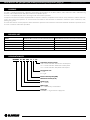
BLAUBOX EC ME 1000 -15 LS31
Automatic control system
S30 — kVent controller with th-Tune control panel
S31 — kVent controller without the control panel
S32 — kVent controller with pGDE control panel
Connection side
L — left
R — right
Electric heater power [kW]
Maximum air ow [m/h]
Heater type
ME — electric
Motor type
EС — electronically commutated
Unit type
BLAUBOX — single-block air supply unit
DESIGNATION KEY
DELIVERY SET
The unit is intended for filtering, supplying and heating purified intake air in offices, hotels, cafés, conference halls, manufacturing
facilities, retail establishments and other residential and public spaces.
The unit is a component part and is not designed for stand-alone operation.
Transported air must not contain any flammable or explosive mixtures, evaporation of chemicals, sticky substances, fibrous materials,
coarse dust, soot and oil particles or environments favourable for the formation of hazardous substances (toxic substances, dust,
pathogenic germs).
The unit must not be used for purposes other than those specified in this manual or outside the ambient conditions specified herein.
The unit is rated for continuous operation.
Name BLAUBOX EC ME 300/400/700/1000/1500/2000/3000/4000 S31 BLAUBOX EC ME 300/400/700/1000/1500/2000/3000/4000 S30/32
BLAUBOX unit 1 pc. 1 pc.
Remote controller – 1 pc.
Outdoor temperature sensor 1 pc. 1 pc.
User’s manual 1 pc. 1 pc.
Packing box 1 pc. 1 pc.

www.blaubergventilatoren.de blauboX ec Me 300/400/700/1000/1500/2000/3000/4000 S30/31/32
6
The unit is designed for indoor application with the ambient temperature ranging from +1 °C up to +40 °C and relative humidity up to
80 % without condensation. The transported air temperature should be from -30 °C to +40 °C with a relative humidity no more than 90%.
The unit is rated as a class I electric appliance.
Hazardous parts access and water ingress protection rating:
• IP22 for the unit connected to the air ducts
• IP44 for the unit motors
The unit design is constantly being improved, thus some models may be slightly different from those described in this manual.
TECHNICAL DATA
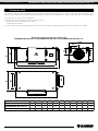
Overall and connection dimensions of the models
BLAUBOX EC ME 300 S30/31/32, BLAUBOX EC ME 400 S30/31/32, BLAUBOX EC ME 700 S30/31/32
L
B
B1
B2
H
H1
L1
L4
L3
øD
L2
Model LL1 L2 L3 L4 HH1 BB1 B2 øD
BLAUBOX EC ME 300 S30/31/32 950 850 903 129 200 310 290 400 313 514 160
BLAUBOX EC ME 400 S30/31/32 972 850 903 160 200 370 351 400 313 514 200
BLAUBOX EC ME 700 S30/31/32 972 850 903 160 225 370 351 460 353 565 250

www.blaubergventilatoren.de
blauboX ec Me 300/400/700/1000/1500/2000/3000/4000 S30/31/32
7
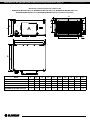
Overall and connection dimensions of the models
BLAUBOX EC ME 1000 S30/31/32, BLAUBOX EC ME 1500 S30/31/32, BLAUBOX EC ME 2000 S30/31/32,
BLAUBOX EC ME 3000 S30/31/32, BLAUBOX EC ME 4000 S30/31/32 (without side panels)
H
H
H1
H2H3
B
M6
B1
B2
L
L1
L2
Model LL1 L2 HH1 H2 H3 BB1 B2
BLAUBOX EC ME 1000 S30/31/32 840 770 500 393 348 95 160 746 653 600
BLAUBOX EC ME 1500 S30/31/32 840 770 500 453 408 95 250 847 754 700
BLAUBOX EC ME 2000 S30/31/32 840 770 500 453 408 95 250 847 754 700
BLAUBOX EC ME 3000 S30/31/32 1140 1070 600 513 468 95 310 944 853 800
BLAUBOX EC ME 4000 S30/31/32 1140 1070 600 563 518 95 360 1087 993 940

www.blaubergventilatoren.de blauboX ec Me 300/400/700/1000/1500/2000/3000/4000 S30/31/32
8
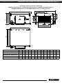
Overall and connection dimensions of the models
BLAUBOX EC ME 1000 S30/31/32, BLAUBOX EC ME 1500 S30/31/32, BLAUBOX EC ME 2000 S30/31/32,
BLAUBOX EC ME 3000 S30/31/32, BLAUBOX EC ME 4000 S30/31/32 (with side panels)
B
L2
L3
H3
H2
B3
B4
L
H
H1
B1
B2
L1
4xM6
Model LL1 L2 L3 HH1 H2 H3 BB1 B2 B3 B4
BLAUBOX EC ME 1000 S30/31/32 900 770 300 190 393 380 220 200 746 653 600 400 420
BLAUBOX EC ME 1500 S30/31/32 900 770 350 220 453 440 270 250 847 754 700 500 520
BLAUBOX EC ME 2000 S30/31/32 900 770 350 220 453 440 320 300 847 754 700 500 520
BLAUBOX EC ME 3000 S30/31/32 1200 1070 400 250 513 500 320 300 944 853 800 600 620
BLAUBOX EC ME 4000 S30/31/32 1200 1070 470 275 563 550 420 400 1087 993 940 700 720

www.blaubergventilatoren.de
blauboX ec Me 300/400/700/1000/1500/2000/3000/4000 S30/31/32
9
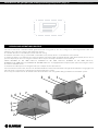
DESIGN AND OPERATING PRINCIPLE
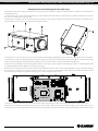
The unit is housed in a sound-insulated galvanized steel casing (item 1). The unit casing has 4 mounting brackets with anti-
vibration connectors for ceiling or wall mounting (item 5).
The air flow direction is indicated by the arrow on the fan casing.
The bottom side of the casing is covered with a removable cover (item 2), which is secured with 4 screws (item 4).
A control unit (item 3) is installed on the casing. The power and control cables are pulled through cable glands (item 6). There is also a
pressure drop relay on the unit casing that activates when the pressure drop at the filter increases (item 8).
Models BLAUBOX EC ME 1000 S30/31/32, BLAUBOX EC ME 1500 S30/31/32, BLAUBOX EC ME 2000 S30/31/32,
BLAUBOX EC ME 3000 S30/31/32, BLAUBOX EC ME 4000 S30/31/32 are equipped with end panels (item 7) for connecting the unit to
the air duct via flexible inserts.
To install the unit directly into a rectangular air duct, the end panels must be removed.
For ease of electrical connection, the units can be ordered with the control unit located either on right or left side of the casing (right- and
left-side versions, respectively, as indicated in the «Designation key» section).
If necessary, the control unit can be moved to the other side of the unit casing before being installed in the ventilation system.
1
6
2
5
4
3
1
2
5
7
8
8
4
6
3
7

www.blaubergventilatoren.de blauboX ec Me 300/400/700/1000/1500/2000/3000/4000 S30/31/32
10
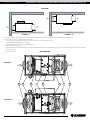
The figure below shows the internals of the left and right version of the units with the removable cover removed.
The air flow direction is indicated by the arrows.
• The inlet and outlet spigots for duct connections (item 1 and 2 respectively);
• air filter with G4 filtration class (item 3);
• block of triacs on the cooling radiator (item 4);
• block of heaters (item 5);
• bracket with two thermostats mounted on it with low threshold and automatic return (item 6) and with high threshold and manual
return (item 7);
• fan unit (item 8).
13 4 5 6 7 8 2
BOTTOM VIEW
TOP VIEW
BLAUBOX ... L BLAUBOX ... R
BLAUBOX ... L
BLAUBOX ... R

www.blaubergventilatoren.de
blauboX ec Me 300/400/700/1000/1500/2000/3000/4000 S30/31/32
11
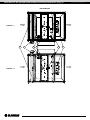
3 4 5 6 7 8
BOTTOM VIEW
BLAUBOX ... R
BLAUBOX ... L

www.blaubergventilatoren.de blauboX ec Me 300/400/700/1000/1500/2000/3000/4000 S30/31/32
12
The unit supplies heated and filtered outdoor air into the room.
The unit uses a frameless centrifugal fan directly driven by an external rotor motor. The fan impeller blades are curved backwards. The
motor has built-in thermal protection and requires no maintenance.
After filtration, the air passes through the block of heaters. The unit automation regulates the power of the heaters in such a manner
so as to maintain the set air temperature at the unit outlet.
The electric heater has double overheating protection.
In case a thermostat with low threshold and automatic return is activated, the heater is turned off and the fan continues to operate, the
air is blown through the unit for a set time, after which the unit is turned off. After the thermostat returns to its initial position, the unit
turns on and continues to operate with the settings active prior to activation of the thermostat. Automatic turn on of the unit is possible
three times in a row within one hour. In case this thermostat activates for the fourth time, the unit will not turn on.
In case a thermostat with high threshold and manual return is activated, the heater is turned off and the unit continues to operate
without being able to turn on the heater. To return the heater to operation, press the manual reset button on the thermostat.
WARNING! Manual restart of the unit after a high threshold thermostat has tripped must be performed by a qualied technician
after the causes of overheating have been eliminated.

www.blaubergventilatoren.de
blauboX ec Me 300/400/700/1000/1500/2000/3000/4000 S30/31/32
13
READ THE USER'S MANUAL BEFORE INSTALLING THE UNIT
WHILE INSTALLING THE UNIT ENSURE CONVENIENT ACCESS FOR SUBSEQUENT
MAINTENANCE AND REPAIR
ALL OPERATIONS DESCRIBED IN THIS USER’S MANUAL MUST BE PERFORMED BY
QUALIFIED PERSONNEL ONLY, PROPERLY TRAINED AND QUALIFIED TO INSTALL AND
MAINTAIN VENTILATION EQUIPMENT.
DO NOT ATTEMPT TO INSTALL THE PRODUCT YOURSELF.
IT IS UNSAFE AND IMPOSSIBLE WITHOUT SPECIAL KNOWLEDGE
MOUNTING AND SETUP
The units are installed between the ducts, taking into account the direction of air flow, which is indicated by an arrow on the casing.
Units BLAUBOX EC ME 300 S30/31/32, BLAUBOX EC ME 400 S30/31/32, BLAUBOX EC ME 700 S30/31/32 have spigots for connecting
to air ducts with round cross-section.
Units BLAUBOX EC ME 1000 S30/31/32, BLAUBOX EC ME 1500 S30/31/32, BLAUBOX EC ME 2000 S30/31/32,
BLAUBOX EC ME 3000 S30/31/32, BLAUBOX EC ME 4000 S30/31/32 are installed in a rectangular air duct system through flexible inserts.
For direct installation of units BLAUBOX EC ME 1000 S30/31/32, BLAUBOX EC ME 1500 S30/31/32, BLAUBOX EC ME 2000 S30/31/32,
BLAUBOX EC ME 3000 S30/31/32, BLAUBOX EC ME 4000 S30/31/32 in a rectangular air duct system, the end panels must be removed.
WARNING!
• To reduce aerodynamic losses related to air flow turbulence, use shaped reducers in order to reduce or increase the cross-section
of air ducts.
• To minimise turbulence-induced air pressure losses, connect the straight air duct sections on both sides of the unit. Minimum
straight air duct length: equal to 1 air duct diameter on intake side and 3 air duct diameters on outlet side
• It is necessary to protect the internal parts of the unit from penetration of foreign objects. For example, install a grill with a cell side
size of no more than 12.5 mm to prevent free access to the fan and foreign objects from entering the unit.
• It is recommended to connect the duct through a flexible connection to reduce noise and vibration transmission. Such connections
allow compensating for possible mounting inaccuracies when connecting the unit to air ducts.
• The equipment and air ducts that are to be connected must have their own mounting bracket in order to avoid transferring their
own weight loads to the unit.
The unit must be mounted so that it can be accessed for service purposes. Enough space must be provided for the cover to open all
the way. After removing the screws, the cover will hang on special cables.
Installation is possible on the ceiling or on the wall in such a way that the air flow is horizontal. In this case, the control unit can be
located both above and below.
The mounting is carried out at 4 points with mounting brackets. It is recommended to use anchor threaded rods with nuts for fastening
the unit. The vibration mounts on the unit casing must fit snugly against the ceiling or wall surface.
Fasteners for the unit mounting are not included into delivery set and should be ordered separately. While choosing fasteners consider
the material of the mounting surface and the unit weight. For selection of the fasteners for unit mounting please refer to a service
technician.
Install the outdoor temperature sensor in the air duct downstream of the unit along the air flow.
the units are available in the right- or left-side versions depending on the location of the control unit relative to the air flow direction. The
unit is designed so that the control unit can be moved to the opposite side of the casing. This allows for a more rational placement of
the equipment when installing the ventilation system.

www.blaubergventilatoren.de blauboX ec Me 300/400/700/1000/1500/2000/3000/4000 S30/31/32
14
Moving the control unit to the opposite side of the casing
If you want to move the control unit before connecting the unit to the power supply and external devices, perform the below steps in
the following order:
1. Position the unit on the surface by placing it on the vibration mounts with the removable cover upward. Remove the control
box cover as shown in the figure below.
2. Remove the removable cover from the unit casing. To do this, remove the 4 screws that secure the cover and the screws that secure
the safety cables to the unit casing as shown in the figure below.
3. Label the wires connected to all devices in the control unit. Remember, photograph or write down the connection points of all cables.
4. Disconnect all cables and pull them out through cable glands inside the unit casing. Route all cables to the other side of the unit casing
and run them through the cable glands on the opposite side. Secure the cables in the new position with cable ties.
5. Move the triac assembly on the cooling radiator (item 4 in the figure in the «Design and operating principles» section) together with
the mounting bracket to the opposite side of the unit casing.
6. Remove the screws that secure the chassis with the automation elements in the control unit (highlighted in gray in the figure below).
Then remove the screws that secure the control unit cover. The screws are indicated with arrows in the figure below. Install the control
unit and chassis on the other side of the casing in reverse order using the same screws.
7. Connect all cables inside the unit in the new location at the same points as before disassembly. Reinstall the control unit cover.
8. Reinstall the removable cover of the unit casing. The cover can be rotated and secured so that it hangs on the safety cables on the
convenient side during maintenance work on the unit. Threaded holes are provided on both sides for attaching the cables to the casing.

www.blaubergventilatoren.de
blauboX ec Me 300/400/700/1000/1500/2000/3000/4000 S30/31/32
15
CONNECTION TO POWER MAINS
DISCONNECT THE POWER SUPPLY PRIOR TO ANY OPERATIONS WITH THE UNIT.
CONNECTION OF THE UNIT TO POWER MAINS IS ALLOWED BY A QUALIFIED
ELECTRICIAN WITH A WORK PERMIT FOR THE ELECTRIC UNITS UP TO 1000 V AFTER
CAREFUL READING OF THE PRESENT USER’S MANUAL.
THE RATED ELECTRICAL PARAMETERS OF THE UNIT ARE GIVEN ON THE
MANUFACTURER’S LABEL
The connection must be made using durable, insulated and heat-resistant conductors (cables, wires).
The external power input must be equipped with an automatic circuit breaker built into the stationary wiring to open the circuit in the
event of overload or short-circuit.
The position of the external circuit breaker must ensure free access for quick unit power-off.
The trip current of the automatic circuit breaker must exceed the maximum current consumption of the unit (refer to the «Technical
data» section or to the unit label). It is recommended to select the rated current of the circuit breaker from the standard series, following
the maximum current of the connected unit.
The circuit breaker is not included in the delivery set.
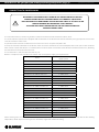
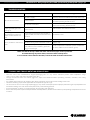
Below is a complete list of ventilation unit models and electric power supply system parameters.
Model Parameters of the electric power
supply system
BLAUBOX EC ME 300-1.7 S30/31/32 1~230 V, 50 Hz
BLAUBOX EC ME 300-5.1 S30/31/32 3~400 V, 50 Hz
BLAUBOX EC ME 400-2.4 S30/31/32 1~230 V, 50 Hz
BLAUBOX EC ME 400-3.3 S30/31/32 3~400 V, 50 Hz
BLAUBOX EC ME 400-6.0 S30/31/32 3~400 V, 50 Hz
BLAUBOX EC ME 700-3.0 S30/31/32 3~400 V, 50 Hz
BLAUBOX EC ME 700-6.0 S30/31/32 3~400 V, 50 Hz
BLAUBOX EC ME 700-9.0 S30/31/32 3~400 V, 50 Hz
BLAUBOX EC ME 1000-6.0 S30/31/32 3~400 V, 50 Hz
BLAUBOX EC ME 1000-12.0 S30/31/32 3~400 V, 50 Hz
BLAUBOX EC ME 1000-15.0 S30/31/32 3~400 V, 50 Hz
BLAUBOX EC ME 1500-9.0 S30/31/32 3~400 V, 50 Hz
BLAUBOX EC ME 1500-15.0 S30/31/32 3~400 V, 50 Hz
BLAUBOX EC ME 1500-18.0 S30/31/32 3~400 V, 50 Hz
BLAUBOX EC ME 2000-12.0 S30/31/32 3~400 V, 50 Hz
BLAUBOX EC ME 2000-18.0 S30/31/32 3~400 V, 50 Hz
BLAUBOX EC ME 2000-24.0 S30/31/32 3~400 V, 50 Hz
BLAUBOX EC ME 3000-18.0 S30/31/32 3~400 V, 50 Hz
BLAUBOX EC ME 3000-27.0 S30/31/32 3~400 V, 50 Hz
BLAUBOX EC ME 3000-45.0 S30/31/32 3~400 V, 50 Hz
BLAUBOX EC ME 4000-24.0 S30/31/32 3~400 V, 50 Hz
BLAUBOX EC ME 4000-45.0 S30/31/32 3~400 V, 50 Hz
BLAUBOX EC ME 4000-54.0 S30/31/32 3~400 V, 50 Hz
When selecting wires cross-section, it is necessary to take into account the maximum permissible load current and the wire heating
temperature, which depends on the type of its insulation, length and method of routing.

www.blaubergventilatoren.de blauboX ec Me 300/400/700/1000/1500/2000/3000/4000 S30/31/32
16
To connect the power supply and external devices, unscrew the two screws on the cover of the control unit and remove the cover, as
shown in the figure in the «Mounting and set-up» section.
Lead the power supply cable and the cables for connecting the control panel and the outdoor temperature sensor through the cable
glands in the control unit and connect them according to the wiring diagram.
WARNING! To ensure correct operation of the unit’s controls, the outdoor temperature sensor must be installed in the supply
air duct downstream of the unit along the air ow.
The sensor is provided in the delivery set and must be connected by the user according to the external connection diagram.
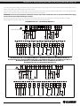
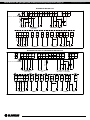
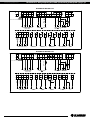
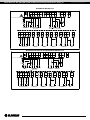
Wiring diagrams for power supply and external devices are shown in the figure below.
BLAUBOX EC ME 300-1.7, BLAUBOX EC ME 400-2.4
1A
SM1*/SM2*
K2*
K2:A2 K2:A1
4 5 6
2,5A0,5A
SM1*/SM2*
X1
SM_L
SM_L1
SM_N
F2 F3 F4 1 2 3
X1
F5*
K2.1*
M2*
3,15A
F1
L1N NPE
L1N N
out
0-10V
Y2
CCU*
+24V
GND
5 6
in
0-10V
B3
B1*
+24V
GND
Rx-
Rx+
GND
56789
X2
A3**
GND
1
D_in
DI1
PD1*
GND
2
PK1*
20
in
0-10V
B1
X2 A1 X2 A1 A1
D_in
DI3
X2
GND
3
A1 X2 A1
RT1
12,50,5 X1X1
3,15
X2 X2 A1 X2 A1 A1 X2 A1 X2 A1
УAловите свое
Power input
~230V, 50Hz
Electric shock hazard!
or
Gray
White
Brown
Yellow
Green
BLAUBOX EC ME 300-5.1, BLAUBOX EC ME 400-3.3, BLAUBOX EC ME 400-6.0, BLAUBOX EC ME 700-3.0,
BLAUBOX EC ME 700-6.0 EC, BLAUBOX EC ME 700 E-9.0, BLAUBOX EC ME 1000-6.0, BLAUBOX EC ME 1000-12.0,
BLAUBOX EC ME 1000-15.0, BLAUBOX EC ME 1500-9.0, BLAUBOX EC ME 1500-15.0,
BLAUBOX EC ME 1500-18.0, BLAUBOX EC ME 2000-12.0
1A
SM1*/SM2*
K2*
K2:A2 K2:A1
4 5 6
2,5A0,5A
SM1*/SM2*
X1
SM_L
SM_L1
SM_N
F2 F3 F4 1 2 3
X1
F5*
K2.1*
M2*
3,15A
F1
L1 L2 L3N NPE
L1 L2 L3N N
out
0-10V
Y2
CCU*
+24V
GND
5 6
in
0-10V
B3
B1*
+24V
GND
Rx-
Rx+
GND
56789
X2
A3**
GND
1
D_in
DI1
PD1*
GND
2
PK1*
20
in
0-10V
B1
X2 A1 X2 A1 A1
D_in
DI3
X2
GND
3
A1 X2 A1
RT1
12,50,5 X1X1
3,15
X2 X2 A1 X2 A1 A1 X2 A1 X2 A1
or
Electric shock hazard!
Power input
~380V, 50Hz
Gray
White
Brown
Yellow
Green

www.blaubergventilatoren.de
blauboX ec Me 300/400/700/1000/1500/2000/3000/4000 S30/31/32
17
BLAUBOX EC ME 3000-18.0
1A
SM1*/SM2*
K2*
K2:A2 K2:A1
456
3,15A
0,5A
SM1*/SM2*
X1
SM_L
SM_L1
SM_N
F2 F3 F4 1 2 3
X1
F5*
K2.1*
M2*
3,15A
F1
L1 L2 L3N NPE
L1 L2 L3N N
out
0-10V
Y2
CCU*
+24V
GND
5 6
in
0-10V
B3
B1*
+24V
GND
Rx-
Rx+
GND
56789
X2
A3**
GND
1
D_in
DI1
PD1*
GND
2
PK1*
20
in
0-10V
B1
X2 A1 X2 A1 A1
D_in
DI3
X2
GND
3
A1 X2 A1
RT1
1
3,15
0,5 X1X1
3,15
X2 A1 X2 A1 A1 X2 A1 X2 A1
Electric shock hazard!
~380V, 50Hz
Power input or
Gray
White
Brown
Yellow
Green
BLAUBOX EC ME 2000-18.0, BLAUBOX EC ME 2000-24.0
1A
SM1*/SM2*
K2*
K2:A2 K2:A1
456
2,5A0,5A
SM1*/SM2*
X2
L3NNPE
SM_L
SM_L1
SM_N
F2L3NN F3 F4 1 2 3
X1
F5*
K2.1*
M2*
3,15A
F1
L1 L2 L3NPE
L1 L2 L3N
X2
X3
GND
3
X3
out
0-10V
Y2
A1
CCU*
D_in
DI3
A1
PK1*
+24V
GND
5 6
X3
in
0-10V
B1
A1
B1*
20
+24V
GND
Rx-
Rx+
GND
56789
X3
A3**
GND
1
X3
D_in
DI1
A1
PD1*
GND
2
NTC
B3
A1
RT1
12,50,5 X2
3,15A
X2
X3 X3
A1 A1 X3A1
X3 X3 A1 A1
or
Electric shock hazard!
Power input
Gray
White
Brown
Yellow
Green
~380V, 50Hz

www.blaubergventilatoren.de blauboX ec Me 300/400/700/1000/1500/2000/3000/4000 S30/31/32
18
BLAUBOX EC ME 3000-27.0
1A
SM1*/SM2*
K2*
K2:A2 K2:A1
456
3,15A
0,5A
SM1*/SM2*
X2
L3NNPE
SM_L
SM_L1
SM_N
F2L3NN F3 F4 1 2 3
X1
F5*
K2.1*
M2*
3,15A
F1
L1 L2 L3NPE
L1 L2 L3N
X2
X3
GND
3
X3
out
0-10V
Y2
A1
CCU*
D_in
DI3
A1
PK1*
+24V
GND
5 6
X3
in
0-10V
B1
A1
B1*
20
+24V
GND
Rx-
Rx+
GND
56789
X3
A3**
GND
1
X3
D_in
DI1
A1
PD1*
GND
2
NTC
B3
A1
RT1
1A
3,15A
0,5A X2X1
3,15A
X2
X3 X3
A1 A1 X3A1
X3 X3 A1 A1
or
Electric shock hazard!
Power input
Gray
White
Brown
Yellow
Green
~380V, 50Hz
BLAUBOX EC ME 4000-24.0
1A
SM1*/SM2*
K2*
K2:A2 K2:A1
456
0,5A
SM1*/SM2*
X2
L3NNPE SM_L
SM_L1
SM_N
F2L3NN F3 F4 1 2 3
X1
F5*
K2.1*
M2*
3,15A
F1
L1 L2 L3NPE
L1 L2 L3N
X2 5A
X3
GND
3
X3
out
0-10V
Y2
A1
CCU*
D_in
DI3
A1
PK1*
+24V
GND
5 6
X3
in
0-10V
B1
A1
B1*
20
+24V
GND
Rx-
Rx+
GND
56789
X3
A3**
GND
1
X3
D_in
DI1
A1
PD1*
GND
2
NTC
B3
A1
RT1
10,5 X21
3,15
X2 5
X3 X3
A1 A1 X3A1
X3 X3 A1 A1
or
Electric shock hazard!
~380V, 50Hz
Power input
Gray
White
Brown
Yellow
Green

www.blaubergventilatoren.de
blauboX ec Me 300/400/700/1000/1500/2000/3000/4000 S30/31/32
19
BLAUBOX EC ME 3000-45.0
1A
3,15A
0,5A
X1
M2*
3,15A
F1
L1 L2 L3NPE
L1 L2 L3N
X2
F5*
K2.1*
F2 F4 F3
X4
SM1*/SM2*
K2*
K2:A2 K2:A1
4 5
SM1*/SM2*
SM_L
SM_L1
SM_N
123
X2
X3
GND
3
X3
out
0-10V
Y2
A1
CCU*
D_in
DI3
A1
PK1*
+24V
GND
5 6
X3
in
0-10V
B1
A1
B1*
20
+24V
GND
Rx-
Rx+
GND
56789
X3
A3**
GND
1
X3
D_in
DI1
A1
PD1*
GND
2
NTC
B3
A1
RT1
1
3,15A
0,5
3,15
X2 X4X2
X3 X3
A1 A1 X3A1
X3 X3 A1 A1
or
Electric shock hazard!
~380V, 50Hz
Power input
Gray
White
Brown
Yellow
Green
BLAUBOX EC ME 4000-45.0 EC, BLAUBOX EC ME 4000-54.0
1A0,5A
X1
M2*
3,15A
F1
L1 L2 L3NPE
L1 L2 L3N
X2
F5*
K2.1*
F2 F4 F3
X4
SM1*/SM2*
K2*
K2:A2 K2:A1
4 5
SM1*/SM2*
SM_L
SM_L1
SM_N
1 2 3
X2 5A
X3
GND
3
X3
out
0-10V
Y2
A1
CCU*
D_in
DI3
A1
PK1*
+24V
GND
5 6
X3
in
0-10V
B1
A1
B1*
20
+24V
GND
Rx-
Rx+
GND
56789
X3
A3**
GND
1
X3
D_in
DI1
A1
PD1*
GND
2
NTC
B3
A1
RT1
10,5
3,15
X2 X4X2 5
X3 X3
A1 A1 X3A1
X3 X3 A1 A1
or
Electric shock hazard!
Power input
Gray
White
Brown
Yellow
Green
~380V, 50Hz

www.blaubergventilatoren.de blauboX ec Me 300/400/700/1000/1500/2000/3000/4000 S30/31/32
20
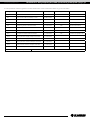
The interpretation of the designations and the characteristics of the connection cables are given in the table.
Designation Name Wire type Type Note
A3** Remote controller 5 x 0.25 mm ThTune
B1* CO sensor or RH1 humidity sensor 3 x 0.25 mm
CCU* Cooler control 2 x 0.75 mm NO
F5* Fuse for the exhaust motor Depending on the M2
K2* Switching on the exhaust motor 2 x 0.5 mm NO For M2 connection
M2* Extract fan 2 x 0.75 mm On/Off
PD1* Differential pressure sensor 2 x 0.25 mm NO
PK1* Fire panel remote control contact 2 x 0.5 mm NC Remove the jumper 20
SM1* Three-position supply damper actuator 3 x 0.5 mm
SM1* Two-position supply damper actuator 2 x 0.5 mm
SM2* Three-position exhaust damper actuator 3 x 0.5 mm
SM2* Two-position exhaust damper actuator 2 x 0.5 mm
RT1 Outdoor temperature sensor 2 x 0.25 mm up to 10 m
*Is not included in the delivery set. ** The unit is delivered with a Th Tune remote controller at the customer request
Page is loading ...
Page is loading ...
Page is loading ...
Page is loading ...
Page is loading ...
Page is loading ...
Page is loading ...
Page is loading ...
-
 1
1
-
 2
2
-
 3
3
-
 4
4
-
 5
5
-
 6
6
-
 7
7
-
 8
8
-
 9
9
-
 10
10
-
 11
11
-
 12
12
-
 13
13
-
 14
14
-
 15
15
-
 16
16
-
 17
17
-
 18
18
-
 19
19
-
 20
20
-
 21
21
-
 22
22
-
 23
23
-
 24
24
-
 25
25
-
 26
26
-
 27
27
-
 28
28


BLAUBERG Blaubox EC ME User manual
- Category
- Split-system air conditioners
- Type
- User manual
Ask a question and I''ll find the answer in the document
Finding information in a document is now easier with AI
Related papers
-
BLAUBERG Iso-RB User manual
-
BLAUBERG Box-S Duct Rectangular Smoke Extraction Fan User manual
-
BLAUBERG Reneo-Fit D 100 S14 User manual
-
BLAUBERG Centro-M 100 User manual
-
BLAUBERG BlauAIR CFH 800 User manual
-
BLAUBERG BlauAIR CFH 6000 User manual
-
BLAUBERG Box EC User manual
-
BLAUBERG KOMFORT EC DBE 300 User manual
-
-
Other documents
-
 BLAUBERG Ventilation MLCD E2 User manual
-
BLAUBERG Ventilation BlauAIR CFH User manual
-
Blaupunkt VPC 10D User manual
-
BLAUBERG Ventilation KOMFORT EC DBW 550 User manual
-
-
-
-
-
-
