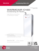
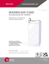
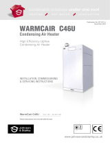
Page is loading ...

www.johnsonandstarley.co.uk
FM 565200
www.johnsonandstarley.co.uk
Johnson & Starley Ltd
Rhosili Road
Brackmills, Northampton
NN4 7LZ
WarmCair Condensing Warm Air
and Hot Water
FM 525200
USERS INSTRUCTIONS
WARMCAIR
Condensing Air & Water Heater
High Efficiency Downflow
Condensing Air & Water Heater
Warmcair C10DW - G.C. No. 43-417-59
Warmcair C16DW - G.C. No. 43-417-60
Warmcair C20DW - G.C. No. 43-417-61
These instructions are to be left with the User
Publication No. ZZ 1449-3
November 2021

www.johnsonandstarley.co.uk
2
CONTENTS
1. General Information 3
2. Temperature Control 3
3. Air Filter 3
4. Heater Not Giving the Service Required 4
5. The Heater Control Panel 4
6. To Light the Heater 5
7. Operating Functions 5
8. Special Modes 6
9. Servicing & Maintenance 6
10 . Escape of Gas 6
11 . Cleaning 7
12 . Troubleshooting 7
13 . Additional Information 7
NOTE
This appliance is not intended for use by persons (including children) with reduced physical, sensory or
mental capabilities, or lack of experience and knowledge, unless they have been given supervision or
instruction concerning use of the appliance by a person responsible for their safety.
Children should be supervised to ensure that they do not play with the appliance.
THESE INSTRUCTIONS SHOULD BE LEFT WITH THE
USER AFTER INSTALLATION
The Benchmark SchemeThe Benchmark Scheme
Johnson & Starley Ltd is a licensed member of the Benchmark
Scheme which aims to improve the standards of installation and commissioning of domestic heating and hot
water systems in the United Kingdom and to encourage regular servicing to optimise safety, efficiency and
performance.
Benchmark is managed and promoted by the Heating and Hotwater Industry Council. For more information visit
www.centralheating.co.uk
Please ensure that the installer has fully completed the Benchmark Checklist on the inside back pages of the
installation instructions supplied with the product and that you have signed it to state that you have received a full
and clear explanation of its operation. The installer is legally required to complete a commissioning checklist as a
means of complying with the appropriate Building Regulations (England and Wales).
All installations must be notified to Local Area Building Control either directly or through a Competent Persons
Scheme. A Building Regulations Compliance Certificate will then be issued to the customer who should, on
receipt, write the Notification Number on the Benchmark Checklist.
This product should be serviced regularly to optimise its safety, efficiency and performance. The service engineer
should complete the relevant Service Record on the Benchmark Checklist after each service.
The Benchmark Checklist will be required in the event of any warranty work and as supporting documentation
relating to home improvements in the optional documents section of the Home Improvements.
In the interest of continuous development Johnson and Starley reserve the right to change specification without prior notice.
Johnson and Starley prides itself on its ability to supply spare parts quickly and efficiently.

3
Sales/Spares & Replacement Help Line 01604 762881
1. GENERAL INFORMATION
WARNING: THIS APPLIANCE MUST BE EARTHED
IMPORTANT: IT IS A STATUTORY REQUIREMENT THAT ALL GAS APPLIANCES
BE INSTALLED BY COMPETENT PERSONS, (i.e. GAS SAFE REGISTERED
INSTALLERS. GAS SAFE MEMBERSHIP ENQUIRIES - TEL: 0800 408 5500)
IN ACCORDANCE WITH THE GAS SAFETY (INSTALLATION AND USE) REGULATIONS
(CURRENT EDITION). FAILURE TO COMPLY WITH THESE REGULATIONS MAY RESULT
IN PROSECUTION.
1.1 The WarmCair is a floor mounted, condensing heater, featuring full sequence automatic spark
ignition and fan assisted combustion. Due to the high efficiency of the heater, condensate is
produced from the flue gases and this is drained to a suitable disposal point through a plastic
waste pipe at the base of the heater. A condensate “plume” will also be visible at the flue terminal.
2. TEMPERATURE CONTROL
2.1 THERMISTA-STAT OPERATION (if fitted)
2.1.1 The numbers on the Thermista-stat dial represent levels of warmth. When you select a
number, the heater will automatically operate to maintain this level. You will soon find the
setting with which you are most comfortable, and it is suggested that you start at mark
6, making adjustments up or down until a satisfactory level is reached.
2.2 ROOM THERMOSTAT OPERATION (optional)
2.2.1 The room thermostat enables you to select the room temperature that you require.
When the air temperature surrounding the thermostat reaches the selected tempera-
ture, the thermostat will switch the heater off. The thermostat will then automatically al-
low the heater to cycle on and off to maintain the selected room temperature.
2.3 CONTROL OF YOUR HEATING SYSTEM
2.3.1 You can control the heat to each room by opening and closing the warm air outlets, but
not more than half of these outlets should be closed at any time or the performance of
the heating system may be adversely affected.
2.3.2 Warm air outlets in the room where the Thermista-stat or room thermostat is sited should
always be left open to ensure that the heating system is properly controlled.
2.4 SUMMER AIR CIRCULATION (if fitted)
2.4.1 During hot weather, unheated air can be circulated around the home, by turning the
heating requirement off and setting the Summer Air Circulation switch to “ON”. This
switches the heater’s fan on, and circulates air around the home through the air outlets.
2.5 ECONOMIC OPERATION
2.5.1 Economic efficiency can be achieved by setting the Thermista-stat or room thermostat
to the lowest setting that you find acceptable.
2.5.2 Overnight in prolonged severe weather, it is better to set the air heater Time Control (if
fitted), to “ON ALL TIME”, and reduce the Thermista-stat or room thermostat setting to
provide general background heating. Resetting the controls to normal settings on rising
will quickly raise the room temperature.
Recommended background heating settings:
Thermista-stat: Mark 4
Room thermostat: 13°C (55°F)
3. AIR FILTER
IMPORTANT: The air filter should be cleaned every two weeks during the heating season, or every week
for the first month in new homes in order to clear builder’s dust, etc. If you are using a Cleanflow electronic
air cleaner, refer to ZZ 0539.
3.1 To clean the air filter, withdraw it from the heater and clean it using either a soft brush or vacuum
cleaner before refitting it to the heater. DO NOT allow the filter to become clogged, or the
heater output will be greatly reduced and fuel will be wasted. Do not use the heater
without a filter.

www.johnsonandstarley.co.uk
4
FIGURE 1. LED DISPLAY FUNCTIONS
4. HEATER NOT GIVING THE SERVICE REQUIRED
5.1 Check that the Thermista-stat or room thermostat and Time Control (if fitted) are correctly set to
your requirements, and that at least half of the warm air outlets are open, especially in the room
where the temperature control is sited.
5.2 Check if the air filter is clogged, and clean as instructed in Section 3.
5.3 If the fan does not work properly, ensure that the Summer Air Circulation switch (if fitted) is set to
“OFF”.
5.4 SERVICE ARRANGEMENTS
NEW APPLIANCES
Service is supplied under guarantee by the installer for an agreed period. Thereafter, should you
have difficulty in obtaining service, Johnson & Starley Service Department will provide information
of suitable service companies.
5. THE HEATER CONTROL PANEL
K1 K7
K2 K6
K3 K5
K4
TABLE 1 DESCRIPTION
K1 No Function
K2 No Function
K3 Inquiry Mode
K4 Reset
K5 Mode
K6 Decrease Temperature
K7 Increase Temperature

5
Sales/Spares & Replacement Help Line 01604 762881
FIGURE 2.
6. TO LIGHT THE HEATER
7.1 Switch the mains power on and the LED display will show “AP” (Air Purge).
This puts the heater into the Air Purge mode (this process lasts 2 minutes).
See Figure 2 and check Section 15.3 in the Installation, Commissioning and
Servicing Instructions. This process can be skipped by pressing K4 (Reset).
7.2 Choose the desired mode, Off or Heating, by pressing K5. Heating mode
comprises CH (Central Heating) mode and DHW (Domestic Hot Water)
mode.
7. OPERATING FUNCTIONS
7.1 CENTRAL HEATING (CH) MODE
If Heating mode is chosen and there is no demand for hot water, the heater operates in Central
Heating (CH) mode, the display will flash showing a radiator, a small flame and the current
temperature. The flame symbol grows with the demand for heat. Once the required temperature
is reached, the display will go back to standby (in which the radiator on the screen does not
flash). If a Summer Air Circulation switch is fitted, circulation of unheated air will be available as
well.
Approximate flow temperatures for the heater thermostat settings
are shown in Table 2 below.
7.2 DOMESTIC HOT WATER (DHW) MODE
DHW has priority over central heating, so the central heating will stop if hot water is being
demanded and the heater will operate in DHW mode. Water heating temperature can be set by
pressing the + (K7) and - (K6) buttons to the desired temperature.
7.3 TO SHUT DOWN THE BOILER
Set the mode to “OFF” (by pressing K5).
To relight the heater repeat the procedure detailed in Section 6.
7.4 FROST PROTECTION
If no system frost protection is provided and frost is likely during a short absence from home,
leave the heating controls (if fitted) at a reduced temperature setting. For longer periods, the
entire system should be drained.
If the system includes a frost thermostat then, during cold weather, the boiler should be turned
“OFF” at the time switch (if fitted) ONLY. The mains supply should be left switched ON, with the
heater thermostat left in the normal running position.
7.5 CONDENSATE DRAIN
The condensate drain must not be modified or blocked.
Blockage of the condensate drain, caused by debris or freezing, can cause automatic shutdown
of the heater.
If freezing is suspected and the pipe run is accessible an attempt may be made to free the
obstruction by pouring hot water over the exposed pipe and clearing any blockage from
the end of the pipe. If this fails to remedy the problem, the assistance of a Gas Safe Registered
Engineer (United Kingdom) or a Registered Gas Installer (RGII, Ireland) should be sought.
TABLE 2
Setting (Buttons K6 and K7) CH Flow Temperature (°C)
Minimum 20 °C
Maximum
80 °C FIGURE 3.

www.johnsonandstarley.co.uk
6
8. SPECIAL MODES
IMPORTANT: SPECIAL MODES MUST BE HANDLED ONLY BY COMPETENT PERSONS
8.1 TEST MODE
8.1.1 Press and hold K6 and K7 for 5 seconds.
8.1.2 Use K6 and K7 to select the required setting.
8.1.3 To leave the Test mode, press “Reset” (K4).
8.2 INSTALLER MODE
8.2.1 Press and hold “Reset” (K4) for 10 seconds.
8.2.2 To leave the Installer mode, press “Mode” (K5)
8.3 INQUIRY MODE
8.3.1 Press and hold K3 for 10 seconds.
8.3.2 To leave the Inquiry mode, press “Reset” (K4).
9. SERVICING & MAINTENANCE
9.1 It is recommended that a full maintenance check on your appliance is made annually, and that
a service contract is taken out on completion of the guarantee period. Your installer will give you
details of arrangements for this service. If your installer has difficulty in providing this information,
please contact the Johnson & Starley Service Department, which will provide information of
suitable service companies.
9.2 The appliance should be serviced at least once a year by a Gas Safe Registered Engineer
(United Kingdom) or a Registered Gas Installer (RGII, Ireland). On completion of the service the
installer should fill in the service section at the rear of the BENCHMARK logbook. All installers
registered with GAS SAFE carry an identification card. This card will have an ID number which
should be recorded in your logbook. If you have any queries regarding your installer you can
contact GAS SAFE by telephone on 0800 408 5500.
10. ESCAPE OF GAS
10.1 Should a gas leak or fault be suspected, contact the National Gas Emergency Service without
delay. Telephone number 0800 111 999. Do NOT search for gas leaks with a naked flame.
GAS LEAKSGAS LEAKS
DO NOT OPERATE ANY ELECTRICAL SWITCHES,
OR USE A NAKED FLAME - TURN OFFOFF GAS SUPPLY
VENTILATE THE AREA BY OPENING THE DOORS AND
WINDOWS
CALL THE NATIONAL GAS EMERGENCY SERVICES ON
TEL:
0800 111999

7
Sales/Spares & Replacement Help Line 01604 762881
11. CLEANING
11.1 For normal cleaning simply dust with a dry cloth. To remove stubborn marks and stains, wipe
with a damp cloth and finish off with a dry cloth. DO NOT use abrasive cleaning materials.
12. TROUBLESHOOTING
12.1 Check that the Thermista-stat and Time Control are set correctly to your requirements and that
at least half of the warm air outlets are open, especially in the room where the Thermista-stat is
located.
12.2 Check that the air filter is not clogged, if so clean as detailed in Section 3.
12.3 If there is a Lockout Error or Blocking Code (similar to Fig. 4 and 5), see Section 21 in the
Installation, Commissioning and Servicing Instructions.
12.4 If the heater will still not operate correctly, contact your local service engineer.
Service arrangements:
a. for new dwellings, servicing is usually supplied for a specific period
under arrangements made by the building contractor.
b. local Authorities often have their own special arrangements.
c. if the above do not apply, contact your local service engineer, or the Service
department at Johnson & Starley Ltd.
13. ADDITIONAL INFORMATION
13.1 For your appliance to work efficiently and for your heating system to perform
satisfactorily, it is absolutely essential to observe the following:
a) DO KEEP CLEAN, and make sure you DO NOT OBSTRUCT any grilles on
the heater, in the heater compartment, or in any walls, windows or doors of the
building.
b) DO CLEAN AND REFIT the air filter at least once per month.
c) DO NOT PLACE ANYTHING (clothing, linen, etc.) in contact with the air heater or its flue
pipe.
d) DO NOT USE the heater compartment for storage or airing.
e) DO NOT turn off the mains electricity supply to the air heater until the gas supply has
been turned off.
NOTE:
IF YOU ARE AWARE OF, OR SUSPECT, A FAULT OF ANY KIND, THE HEATER
MUST NOT BE USED. TURN OFF THE GAS AND ELECTRICAL SUPPLIES TO THE
HEATER AND CONTACT YOUR SERVICE ENGINEER.
13.2 Further information about your WarmCair Condensing Air & Water Heater is available at our
website, www.johnsonandstarley.co.uk (where the Installation, Commissioning and Servicing Instructions
of the appliance can be downloaded).
WarmCair C10DW - Document No. ZZ 1446
WarmCair C16DW - Document No. ZZ 1447
WarmCair C20DW - Document No. ZZ 1448
FIGURE 4.
LOCKOUT ERROR
FIGURE 5.
BLOCKING CODE

Johnson & Starley Ltd
Rhosili Road, Brackmills,
Northampton NN4 7LZ
sales@johnsonandstarley.co.uk
customer.service@johnsonandstarley.co.uk
service@johnsonandstarley.co.uk
marketing@johnsonandstarley.co.uk
Reception/Customer Service
01604 762881
/


