Page is loading ...

CET - s.r.l.
Vers. 1.0
GTM 51
Pag. 1
CET
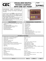
VISUALIZED DIGITAL TIMER
WITH ONE SET POINT
Type:
GTM51
THE INSTRUMENTS OF SERIES GTM ARE DIGITAL
INSTRUMENTS WIDE USABLE IN THE INDUSTRY
FOR THEIR PROGRAMMABLE CHARACTERISTICS
AND THE FLEXIBILITY OF THEIR EMPLOYMENT.
GTM51, TIMER WITH ONE PROGRAMMABLE SET
POINT AND ONE RELAY OUTPUTS. MOREOVER,
IT’S AVAILABLE A TOTALIZER OF THE TIME.
GENERAL FEATURES
PROGRAMMABLE PARAMETERS
• Frontal keyboard in polycarbonate (antiscratch, antioil,
antacid).
• IP65 protection degree
• Accessible parameters with key software
• Removable terminals connection.
• Execution DIN 48 x 48.
• Recessed assembly.
• Special retaining brackets.
• One Set Point
• Automatic Time Reset
• 4 Time Scales
• UP / DOWN / SUPERIOR Timing
• Memory
• Reset Key
• START Input Selection
• OUTPUT Mode Selection
TECHNICAL CHARACTERISTICS
•
POWER SUPPLY IN ALTERNATE CURRENT
•
POWER SUPPLY IN DIRECT CURRENT
•
POWER SUPPLY TOLERANCE
•
ABSORPTION
•
OPERATING TEMPERATURE
•
CLIMATIC CONDITIONS
•
TIMINGS VISUALIZATION
•
TIMINGS SCALES
•
START INPUT
•
AUXILIARY INPUTS POWER SUPPLY
•
COMMAND IMPUTS
•
OUTPUTS
•
RELAY RESET
•
PROGRAMMED DATA MEMORY
: Single power 24 - 110 - 230 Vac (50 / 60 Hz).
: Single power 24 Vdc
: +10% - 15%.
: 2 W - 3 VA.
: -5 °C + 55 °C.
: U.R. 95 % at 40 °C (without condensate).
: 5 digits, 7,5 mm high
: 999h59m - 9h59m59s - 9m59s99c - 999s99c
: programmable as Continuous; Impulsive, Start/Stop
: 24 Vdc - 80 mA available on terminals.
: 1 Start - 1 Reset Timing - 1 Inhibit Timing (Inhibit).
: 1 relay with operating contacts; capacity 2A - 250Vac.
: Manual or automatic with excitation time from 0,1 to 99,9
sec.
: static (without battery)

CET - s.r.l.
Vers. 1.0
GTM 51
Pag. 2
DESCRIPTION OF THE FRONTAL KEYBOARD
ø
WHITE
The key 'LEFT ARROW' in normal operating phase visualizes, blinking, all the programmings executed without the
limitation of the insertion code. The time of scansion of the programmings is given from the pressure of the same
key. It exits automatically from this phase after 5 sec of the last pressure of the same key.
In programming phase it moves the cursor of the figure towards left of a step, than at the beginning it is on the right
side first one on the. At the end it resumes from the first one to right.
ù
WHITE
The key 'UP ARROW' in normal operating phase it enter and exit to the Totalizer.
In programming phase it increases the value of the blinking figure.
ú
BLUE
The key 'PRG' pressed for 2 sec. allows to enter in the programming phase, visualizing on display C.0000.
In the programming phase, pressing key 'PRG' impulsively, it exits from the programming phase. The instrument
exits automatically from the programming phase, 60 sec. after the pressure of the last key.
û
GREEN
The key 'ENT/RES' in normal phase of counting has the 'RESET' function, with the modalities to it attributed in the
programming phase.
In programming phase it confirms and memorizes the visualized data and passes to the successive function. If it has
arrived to list end it resumes from the beginning.
E SERIES INPUTS / OUTPUTS DESCRIPTION
DC POWER
(inputs 1 - 2)
24VDC Power Supply Input of the instrument.
AC POWER
(inputs 3 - 4)
AC Power Supply Input of the instrument; it can be to 24 - 110 - 230 VAC in according to demand.
24 VDC - 80mA
(inputs 12 - 13)
24 VDC – 80 mA auxiliary Power Supply that the instrument supply to feed the Encoder and amplified proximity.
PRI
(input 10)
Input used for the polarization of the command inputs : connecting the PRI output to input 13 it configures the instrument in Negative
logic (NPN), connecting the PRI output to input 12 it configures the instrument in Positive logic (PNP).
START
(inputs 11)
START Input that execute the timing starting as the programming mode; it’s configurable in Positive (PNP) or Negative (NPN) logic
by the dip switches on the rear.
RESET
(inputs 7)
RESET Input that execute the timing reset; it’s configurable in Positive (PNP) or Negative (NPN) logic by the dip switches on the rear.
INHIBIT
(inputs 8)
INHIBIT Input that execute the timing Inhibit; it’s configurable in Positive (PNP) or Negative (NPN) logic by the dip switches on the
rear.
RL1
(inputs 5 - 6 - 9)
Output of Relay RL1, connected to the operation of the WORK timing. The Common, normally Close and normally Open contacts are
available.
Z SERIES INPUTS / OUTPUTS DESCRIPTION
DC POWER
(inputs 2 - 10)
24VDC Power Supply Input of the instrument.
AC POWER
(inputs 2 - 10)
AC Power Supply Input of the instrument; it can be to 24 - 110 - 230 VAC in according to demand.
24 VDC - 80mA
(inputs 7 - 8)
24 VDC – 80 mA auxiliary Power Supply that the instrument supply to feed the Encoder and amplified proximity.
PRI
(input 9)
Input used for the polarization of the command inputs : connecting the PRI output to input 13 it configures the instrument in Negative
logic (NPN), connecting the PRI output to input 12 it configures the instrument in Positive logic (PNP).
START
(inputs 5)
START Input that execute the timing starting as the programming mode; it’s configurable in Positive (PNP) or Negative (NPN) logic
by the dip switches on the rear.
RESET
(inputs 6)
RESET Input that execute the timing reset; it’s configurable in Positive (PNP) or Negative (NPN) logic by the dip switches on the rear.
RL1
(inputs 1 - 3 - 4)
Output of Relay RL1, connected to the operation of the WORK timing. The Common, normally Close and normally Open contacts are
available.
DESCRIPTION OF THE LED’s OPERATION
LED 1 It comes activated to the reaching of the Set Points S1.

CET - s.r.l.
Vers. 1.0
GTM 51
Pag. 3
SET POINT PROGRAMMING
For SET POINT programming access, proceed as follow:
- Press key ‘PRG’ in impulsive mode; on display appears:
Ë1 <
¨0¨20
S.1 = SET POINT 1, main Set Point, programmable between 1 cent and 999h59m (depending
to the selected scale). If programmed = 0 the Set Point remains excluded and the instrument
works like a totalizer and predisposing the count in UP mode.
Key ENT confirms the data. In order to exit the programming, press key PRG.
PROGRAMMING OF THE OPERATION PARAMETERS
The programmable parameters are divided in two groups and protect with a 4 figures code.
In order to approach the programming, proceed in the following way:
- Press key PRG for about 2 sec. On the display appears:
Cod
0000
GROUP 1
:
in order to approach the parameters of group 1, insert code
2357
and press
ENT
Ìê9²9
t.r. = Time of Automatic Reset, programmable from 0.0 to 99.9 sec. This parameter allows to
make to work the instrument in automatic mode. When the timing arrives to the value of S.1, it
automatically resets the count, excites the RL1 relay and it resumes to count. The RL1 relay
remains excited for the set up time in t.r. If the time of reset is programmed = 0 (0.0) the
instrument gets ready to works in manual mode.
Particular cases: if the set up time t.r. is bigger than the time employed to the timing to arrive
to the values of S.1, the relay will never come unactived.
SCÄ 1
SCL. = Time Scale. Selection of the maximum time scale of the timing. It’s possible to choose
between 4 different time scales:
1 = 9m59s99c - 2 = 9h59m59s - 3 = 999h59m - 4 = 999s99c
Cæ UP
Cæ dæ
Cæ SÈ
Count UP / DOWN / Superior.
Count = Up: Up; the timer gets ready to visualize the timing in increasing way (UP), starting
from zero up to the programmed value of set point. To the end of timing it works in Manual or
Automatic mode, as programmed in t.r. function.
Count = dn: Down; the timer gets ready to visualize the timing in decreasing way (DOWN),
starting from the programmed value of set point to zero. To the end of timing it works in
Manual or Automatic mode, as programmed in t.r. function.
Count = Sp: Superior; the timer gets ready to visualize the timing in increasing way (UP),
starting from zero up to the programmed value of set point. To the end of timing it works in
Manual mode and the timing goes on up to a new command (START, RESET, INHIBIT).

CET - s.r.l.
Vers. 1.0
GTM 51
Pag. 4
PROGRAMMING OF THE OPERATION PARAMETERS
The programmable parameters are divided in two groups and protect with a 4 figures code.
In order to approach the programming, proceed in the following way:
- Press key PRG for about 2 sec. On the display appears:
Cod
0000
GROUP 2
:
in order to approach the parameters of group 1, insert code
2413
and press
ENT
NeÆon
NeÆoF
Active or excluded memory.
This parameter allows to program the saving of the current counter value during the power off
the instrument.
MEM.on. = memorization of the count during the power off. When power on the instrument the
display will visualize the last present value in the power off phase.
MEM.of. = excluded memorization of the count; every time that the instrument comes powered
off and then powered on the count comes lost and the instrument restart always from the initial
condition.
RreË 0
reË 3
Function of RESET Key ; this programming enable and disable the RESET function of the
RES frontal key during the normal timing:
RES. 0 = RESET function of the RES key disabled
RES. 1 = RESET function of the main timing only
RES. 2 = RESET function of the global timing only
RES. 3 = RESET function of the main and global timings
Iæ Á
Iæ »
Iæ Ë
Programming of the START Input.
This programming allows to Start the timing in three different modes:
In. I. = Impulsive Mode; the timing starts with the impulsive closing of the START input.
In. C. = Continuously Mode; the timing starts with the closing of the START input; the timing
is interrupted every time the START input comes opened.
In. S. = Start/Stop Mode; the timing starts with the impulsive closing of the START input and it
stops to the subsequent closing. Closing another time the input the timing resume and it stops
to the subsequent closing.
Auto Á
Auto ¾
Programming of the Automatic Reset Mode
This parameter allows to activate the timing to the beginning or the end of the programmed
time of the Automatic Reset
.
Auto I. = Activation of the timing to the beginning of the Automatic Reset Time
Auto F. = Activation of the timing to the end of the Automatic Reset Time
0í1 î
0í1 ÷
Programming of the OUTPUT RL1. This parameter allows to activate the RL1 relay
during the timing
î
or at the end
÷
of the timing.
Ou.1.
î
= Activation of the RL1 relay at the end of the timing
Ou.1.
÷
= Activation of the RL1 relay during the timing
¹È È
¹È ê
Activation mode of the programmed parameters.
With this programming is possible to activate the executed programmings directly to the exit of
the programming or, when exited of the programming, after a RESET (with frontal key or from
rear input)
A.P. = P. Activation of the parameters to the exit of the programming.
A.P. = r. Activation of the parameters to the exit of the programming after a RESET.
Pressing the key ù the totalizer of time will be visualized for 5 sec.
Toì
¨0¨00
The totalizer visualizes the total time that the instrument has show.
It can be resetted through frontal key RES or from RESET input when it is visualized on the
display.

CET - s.r.l.
Vers. 1.0
GTM 51
Pag. 5
DECLARATION OF ‘CE’ CONFORMITY
CE NORMATIVE CONFORMITY
Borgolavezzaro, September, 8th 2000
The building firm:
CET s.r.l.
Head office:
Strada Statale 211, Km 53,3
28071 Borgolavezzaro (No) ITALIA
Tel. 0039 - (0)321 - 885301 Fax. 0039 - (0)321 - 885560
declare that the products:
type :
Electronic Timer
model:
GTM 51
use class:
Industrial
are in conformity with the following normatives:
EN55011
ENV50141
ENV50204
EN61000-4-2
EN61000-4-4
The manufacturing:
CET s.r.l.
________________________________
Signature

CET - s.r.l.
Vers. 1.0
GTM 51
Pag. 6
Programming Notes
----------------------------------------------------------------------------------------------------------------------------------------------------------
----------------------------------------------------------------------------------------------------------------------------------------------------------
----------------------------------------------------------------------------------------------------------------------------------------------------------
----------------------------------------------------------------------------------------------------------------------------------------------------------
----------------------------------------------------------------------------------------------------------------------------------------------------------
----------------------------------------------------------------------------------------------------------------------------------------------------------
----------------------------------------------------------------------------------------------------------------------------------------------------------
----------------------------------------------------------------------------------------------------------------------------------------------------------
----------------------------------------------------------------------------------------------------------------------------------------------------------
----------------------------------------------------------------------------------------------------------------------------------------------------------
----------------------------------------------------------------------------------------------------------------------------------------------------------
----------------------------------------------------------------------------------------------------------------------------------------------------------
----------------------------------------------------------------------------------------------------------------------------------------------------------
----------------------------------------------------------------------------------------------------------------------------------------------------------
----------------------------------------------------------------------------------------------------------------------------------------------------------
----------------------------------------------------------------------------------------------------------------------------------------------------------
----------------------------------------------------------------------------------------------------------------------------------------------------------
----------------------------------------------------------------------------------------------------------------------------------------------------------
----------------------------------------------------------------------------------------------------------------------------------------------------------
----------------------------------------------------------------------------------------------------------------------------------------------------------
----------------------------------------------------------------------------------------------------------------------------------------------------------
----------------------------------------------------------------------------------------------------------------------------------------------------------
----------------------------------------------------------------------------------------------------------------------------------------------------------
----------------------------------------------------------------------------------------------------------------------------------------------------------
----------------------------------------------------------------------------------------------------------------------------------------------------------
----------------------------------------------------------------------------------------------------------------------------------------------------------

CET - s.r.l.
Vers. 1.0
GTM 51
Pag. 7
Z SERIES CONNECTIONS
Z SERIES - INPUT SIGNALS
NPN
-
+ - + - + + -
START INPUT START INPUT START INPUT INPUT FOR
FOR NPN FOR NPN FOR PROXIMITY NPN
CONTACT LOGIC AMPLIFIED RESET
24 VDC
PNP
-
- + - + - + +
START INPUT START INPUT START INPUT INPUT FOR
FOR PNP FOR PNP FOR PROXIMITY PNP
CONTACT LOGIC AMPLIFIED RESET
24 VDC
E SERIES CONNECTIONS
E SERIES - INPUT SIGNALS
NPN
-
+ - + - + + - -
START INPUT START INPUT START INPUT RESET INHIBIT
FOR NPN FOR NPN FOR PROXIMITY NPN
CONTACT LOGIC AMPLIFIED
24 VDC
PNP
-
- + - + - + + +
START INPUT START INPUT START INPUT RESET INHIBIT
FOR PNP FOR PNP FOR PROXIMITY PNP
CONTACT LOGIC AMPLIFIED
24 VDC
7
5
8
9
5
7
8
9
8
9
PROX
ENC
7
8
5
7
6
8
5
7
9
5
8
7
9
7
9
PROX
ENC
7
8
5
8
6
12
11
13
10
11
12
13
10
13
10
PROX
ENC
12
13
11
13
11
12
10
11
13
12
10
12
10
PROX
ENC
12
13
11
12
7
12
8
13
7
13
8
PRI
1
GND
11
2
3
4
5
6
7
8
9
10
+ 24 VDC
RESET
START
RL1
24 VDC
-
+
DC POWER
SUPPLY
PRI
1
GND
11
2
3
4
5
6
7
8
9
10
+ 12VDC
80mA Max
RESET
START
RL1
AC POWER
SUPPLY
24 VDC
-
+
-
+
12 VDC
START
INHIBIT
7
8
9
10
11
12
13
1
2
3
4
5
6
PRI
RESET
POWER SUPPLY
AC
RL1

CET - s.r.l.
Vers. 1.0
GTM 51
Pag. 8
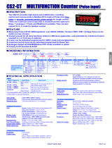
OVERALL DIMENSIONS (mm)
FRONT DRILL TEMPLATE
E SERIES SIDE Z SERIES SIDE
E SERIES REAR
Z SERIES REAR
CET
CETCET
CET
CET
CETCET
CET
S.r.l.
Strada Statale 211 Km 53,550
28071 Borgolavezzaro - NO - ITALY
Tel : ++39 0321-885180/885301/885807
Fax : ++39 0321-885560
http://www.cet-italy.com
e-mail: info@cet-italy.com
Agent:
45
45
48
48
ENT
PRG
electronic timer GTM
L1 L2
RES
CET
CETCET
CET
Ñ5«50
116
93
4
19
44x44
REMOVABLE
TERMINALS
RETAINING
BRACKETS
10
116
93
4
12
44x44
UNDECAL
SOCCAL
RETAINING
BRACKETS
10
44
44
7 8 9 10 11 12 13
1 2 3 4 5 6
44
44
1 11
2
3
4
5
6
7
8
9
10
/