www.bdsensors.com
D
E
E
N
Deutsch
Montageanleitung /
Mounting instructions
Präzisions-Druckmessumformer /
Precision Pressure Transmitter
xact ci und xact i
Zentrale Westeuropa / International
Headquarters Western Europe / International
BD SENSORS GmbH
BD-Sensors-Str. 1
D - 95199 Thierstein
Deutschland / Germany
Tel.: +49 (0) 92 35 / 98 11-0
Fax: +49 (0) 92 35 / 98 11-11
Zentrale Osteuropa /
Headquarters Eastern Europe
BD SENSORS s.r.o.
Hradištská 817
CZ - 687 08 Buchlovice
Tschechische Republik /
Czech Republic
Tel.: +42 (0) 5 72 / 4 11-0 11
Fax: +42 (0) 5 72 / 4 11-4 97
Russland /
Russia
BD SENSORS RUS
39a, Varshavskoe shosse
RU - Moscow 117105
Russland /
Russia
Tel.: +7 (0) 9 59 81 / 09 63
Fax: +7 (0) 9 57 95 / 07 21
Diese Montageanleitung stellt einen Auszug
aus der ausführlichen Betriebsanleitung dar.
Bitte laden Sie sich diese auf unserer Home-
page herunter, falls Sie nicht mit dem Produkt
vertraut sind.
These mounting instructions are an excerpt from the complete
operating manual. It may be downloaded from our homepage, if
you are not familiar with the device.
http://www.bdsensors.de/produkte/download/anleitungen
http://www.bdsensors.com/products/download/manuals
– Technische Änderungen vorbehalten –
– Technical modifications reserved –
WARNUNG! Um Gefährdungen des B
Schäden am Gerät auszuschließen, müssen die beschri
benen Arbeiten von qualifiziertem Fachpersonal durchg
führt werden.
WARNUNG!
Halten Sie sich an Sicherheitshinweise und
Handlungsanw
eisungen, die in d
geführt we
rden. Zusätzlich sind die geltenden Unfallverh
tungsvorschriften, Sicherheitsbestimmungen sowie lande
spezifische
Installationsstandards und die anerkannten
Regeln der Technik einzuhalten.
Haftungsbeschränkung
Bei Nichtbeachtung der Betriebsanleitung, unsa
Verwendung, Veränderung oder Beschädigung des Ger
tes übernimmt der Hersteller keine Haftung.
Bestimmungsgemäße Verwendung
Stellen Sie
sicher, dass das M
berührten Teilen verträglich
schränkt für die An
wendung geeignet
Datenblatt aufgeführten technischen Daten sind verbindlich
und müssen unbedingt eingehalten werden.
Produktidentifikation
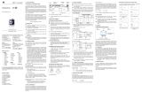
Anzeige-
und Bedienelement
▲-Taste:
Aktivierung des Bedienmodus
im Menüsystem vorwärts bewegen
Anzeigewert erhöhen
▼-Taste:
Aktivierung des Bedienmodus
im Menüsystem
Anzeigewert
verringern
beide Tasten gleichzeitig:
Bestätigung der Menüpunkte und der eingestellten
▼-Taste
Bestell-
code
Nenndruck
eingestellter
Druckbereich
Typenbezeichnung
Anschlussb
optional /
o
p
tionally:
74-06
x|act i
WARNUNG! Um Gefährdungen des B
edienpersonals und
Schäden am Gerät auszuschließen, müssen die beschri
e-
benen Arbeiten von qualifiziertem Fachpersonal durchg
e-
Halten Sie sich an Sicherheitshinweise und
eisungen, die in d
er Betriebsanleitung auf-
rden. Zusätzlich sind die geltenden Unfallverh
ü-
tungsvorschriften, Sicherheitsbestimmungen sowie lande
s-
Installationsstandards und die anerkannten
Regeln der Technik einzuhalten.
Bei Nichtbeachtung der Betriebsanleitung, unsa
chgemäßer
Verwendung, Veränderung oder Beschädigung des Ger
ä-
tes übernimmt der Hersteller keine Haftung.
Bestimmungsgemäße Verwendung
sicher, dass das M
essmedium mit den medien-
berührten Teilen verträglich
und das Gerät uneinge-
wendung geeignet
ist. Die im aktuellen
Datenblatt aufgeführten technischen Daten sind verbindlich
und müssen unbedingt eingehalten werden.
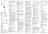
und Bedienelement
Aktivierung des Bedienmodus
im Menüsystem vorwärts bewegen
Anzeigewert erhöhen
Aktivierung des Bedienmodus
im Menüsystem
rückwärts bewegen
verringern
Bestätigung der Menüpunkte und der eingestellten
Werte
Montage
Anschlussschaltbilder
2-Leiter-System (Strom)
2-Leiter System (Strom) HART
WARNUNG! Montieren Sie das Gerät immer im druck-
und stromlosen Zustand!
WARNUNG! Verwenden
Sie zur Abdichtung eine geeign
Druck.
Anschluss nach DIN 3852
Anschluss G1" Konus
Schlüsselweite aus
Kunststoff: max. 3 Nm
G1 1/2" Stahl: ca. 25 Nm
Milchrohr-Anschluss Clamp-
und Varivent
- Zentrieren Sie den Anschluss in -
Zentrieren Sie den Anschluss in der
der Aufnahmearmatur.
Aufnahmearmatur.
- Schrauben Sie die Überwurf- -
Befestigen Sie das Gerät anschließend
mutter auf die Aufnahmearmatur.
durch ein geeignetes Verbindungselement
- Ziehen Sie diese mit einem
(z. B. Halbring
Hakenschlüssel fest. gemäß
den vom Hersteller angegebenen
Vorschriften.
Versorgung +
Versorgung –
UB
A
p
I
OK-Taste
Bargraph
▲-Taste
Display
Nenndruck
Signal Seriennummer
Anschlussb
elegung Versorgung
p
Versorgung +
Versorgung –
UB
I
Verwenden Sie für den elektrischen Anschluss vorzugs-
weise eine abgeschirmte und verdrillte Mehraderleitung.
Anschlussbelegungstabelle
Elektrische
Anschlüsse
M12x1
(4-polig)
Kabelfarben
(DIN 47100)
Versorgung +
Versorgung −
1
3
wh (weiß)
bn (braun)
Schirm Steckergehäuse gn/ye
(grün / gelb)
und stromlosen Zustand!
Sie zur Abdichtung eine geeign
ete Dichtung, entsprechend dem Messstoff und dem zu messenden
Anschluss G1" Konus
DRD- und Flansch-Anschluss
P
N
< 10 bar: 30 Nm Befestigen Sie den Flansch mit 4
P
N
≥ 10 bar: 60 Nm bzw. 8 Schrauben (je nachFlansch-
ausführung) am Gegenflansch.
und Varivent
-Anschluss Temperaturentkoppler
Zentrieren Sie den Anschluss in der
Aufnahmearmatur.
Befestigen Sie das Gerät anschließend
durch ein geeignetes Verbindungselement
(z. B. Halbring
- oder Klappringverbindung)
den vom Hersteller angegebenen
Vorschriften.

D
E
E
N
English
www.bdsensors.com
Montageanleitung /
Mounting instructions
Präzisions-Druckmessumformer /
Precision Pressure Transmitter
xact ci und xact i
Zentrale Westeuropa / International
Headquarters Western Europe / International
BD SENSORS GmbH
BD-Sensors-Str. 1
D - 95199 Thierstein
Deutschland / Germany
Tel.: +49 (0) 92 35 / 98 11-0
Fax: +49 (0) 92 35 / 98 11-11
Zentrale Osteuropa /
Headquarters Eastern Europe
BD SENSORS s.r.o.
Hradištská 817
CZ - 687 08 Buchlovice
Tschechische Republik /
Czech Republic
Tel.: +42 (0) 5 72 / 4 11-0 11
Fax: +42 (0) 5 72 / 4 11-4 97
Russland /
Russia
BD SENSORS RUS
39a, Varshavskoe shosse
RU - Moscow 117105
Russland /
Russia
Tel.: +7 (0) 9 59 81 / 09 63
Fax: +7 (0) 9 57 95 / 07 21
Diese Montageanleitung stellt einen Auszug
aus der ausführlichen Betriebsanleitung dar.
Bitte laden Sie sich diese auf unserer Home-
page herunter, falls Sie nicht mit dem Produkt
vertraut sind.
These mounting instructions are an excerpt from the complete
operating manual. It may be downloaded from our homepage, if
you are not familiar with the device.
http://www.bdsensors.de/produkte/download/anleitungen
http://www.bdsensors.com/products/download/manuals
– Technische Änderungen vorbehalten –
– Technical modifications reserved –
WARNING!
In order t
damages to
the device, the following instructions have to
be performed
by qualified technical
WARNING!
Adhere to the safety
stated in the operation
cupational safety, accident prevention as well as national
installation standards and
niques must in ad
dition be complied with.
Limitation of liability
If the instructions in
the operating manual
to or if the device is inappropriately used
aged, liability is not
assumed and warranty claims will be
excluded.
Intended use
Ensur
e that the medi
wetted parts and that the device is suitable for the applic
tion
without restrictions
rent data sheet is
binding
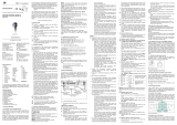
Product identification
Display and operating module
▲-button: enter
operating mode
move forward in the menu system
increase the displayed value
▼-button: enter
operating mode
move
backward in the menu system
decrease the displayed value
both buttons simultaneously:
confirm the menu items and set values
ordering
code
nominal range
setting range
type designation
connector pinout
▼-button
optional /
o
p
tionally:
74-06
x|act i
In order t
o avoid hazards to operators and
the device, the following instructions have to
by qualified technical
personnel.
Adhere to the safety
and operating instructions
manual. Effective regulations on oc-
cupational safety, accident prevention as well as national
installation standards and
approved engineering tech-
dition be complied with.
the operating manual
are not adhered
to or if the device is inappropriately used
, modified or dam-
assumed and warranty claims will be
e that the medi
um is compatible with the media-
wetted parts and that the device is suitable for the applic
a-
without restrictions
. The technical data listed in the cur-
binding
and must definitely be observed.
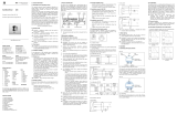
Display and operating module
operating mode
move forward in the menu system
increase the displayed value
operating mode
backward in the menu system
decrease the displayed value
both buttons simultaneously:
confirm the menu items and set values
Mounting
Wiring diagrams
2-wire-system (current)
2-wire-system (current) HART
WARNING!
Install the device only in depressurized and currentless state!
WARNING! Use
a suitable seal, corresponding to the medium and the pressure input.
connection acc. to DIN 3852 c
onnection
wrench size of
plastic: 3 Nm
G1 1/2" steel: approx. 25 Nm
dairy pipe connection
Clamp and Varivent
- Centre the connection in the -
Centre the connection in the
mounting part.
mounting part.
- Screw the cup nut onto the -
Fix the device with a suitable fastening
mounting part. elemen
t (e. g. semi
- Then tighten it with a hook
ring clamp) according to the supplier’s
wrench.
instructions.
nominal range
signal serial number
connector pinout
supply
OK-button
bargraph
▲-button
display
supply +
supply –
VS
A
p
I
p
supply +
supply –
VS
I
For the electrical connection a shielded and twisted
multicore cable is recommended.
MA_xact_D-E_110517
Pin configuration
Electrical
connections
M12x1
(4-pin)
cable colours
(DIN 47100)
Supply +
Supply –
1
3
wh (white)
bn (brown)
Shield plug housing gn/ye
(green / yellow)
Install the device only in depressurized and currentless state!
a suitable seal, corresponding to the medium and the pressure input.
onnection
G1" Konus DRD- and flange connection
P
N
< 10 bar: 30 Nm Fasten the flange with 4 resp.
P
N
≥ 10 bar: 60 Nm 8 screws (depending on flange
version) on the counter flange.
Clamp and Varivent
connection cooling element
Centre the connection in the
mounting part.
Fix the device with a suitable fastening
t (e. g. semi
-ring or retractable
ring clamp) according to the supplier’s
instructions.
/


