Page is loading ...

950-0211revA March 7, 2014
International Refrigeration Products, Inc.
MINI-SPLIT INSTALLATION
AND MAINTENANCE MANUAL
A/C HEAT PUMP
9A45YIMI 9H45YIMI
12A45YIMI 12H45YIMI
12A45ZIMI 12H45ZIMI
18A45ZIMI 18H45ZIMI
24A45ZIMI 24H45ZIMI
9A45YOMI 9H45YOMI
12A45YOMI 12H45YOMI
12A45ZOMI 12H45ZOIMI
18A45ZOMI 18H45ZOMI
24A45ZOMI 24H45ZOMI

950-0211revA - 1 - March 7, 2014
TABLE OF CONTENTS
Note to Installer ………………………………………………………………....2
Installer Supplied Items ………………………………………………….….....3
Parts Included with unit ………………………………………………….….....3
Items for Considerations ………………………………………………….…...3
Unit Installation …………………………………………………………………..5
Unit Installation (indoor) ………………………………………………………..6
Unit Installation (outdoor) ………………………………………………………9
Main Power Wiring ………………………………………………………………10
Controls Wiring ……………………………………………………………..……10
Wiring Diagram……………………………………………………………11
Unit Start Up ……………………………………………………………………13
Refrigerant Charge …………………………………………………………...14
Pressure Curves ……………………………………………………..………15
Specifications………………….…………………………………………17
Troubleshooting………………………………………………………………….22
Importance of a Deep Vacuum…..……………………………………………….23
Warranty ……………………………………………………………………….24
Technical Support …………………………………………………………….24

950-0211revA - 2 - March 7, 2014
Installation and Maintenance Manual
Report shipping damage to carrier IMMEDIATELY. Check units and box exterior for damage.
NOTE TO INSTALLER
This manual is to aid the qualified HVAC contractor in the installation and maintenance of this mini-split
system.
Please read and understand these instructions prior to installing the unit, failure to comply with these
instructions may result in improper installation, operation and maintenance, possibly resulting in fire, electrical
shock, property damage, personal injury or death.
Installers please retain this manual for future reference; pass warranty registration to end user. If technical
assistance is required during installation or start up, please call 704-504-8590 for technical assistance. Before
calling please have the model and serial numbers available.
Safety Instructions
Read all the instructions. Install and operate the system per these instructions.
Use the unit only in the manner described in this manual.
1. Check rating plate for correct system voltage before installing the unit installing and operating a unit with the
incorrect voltage may result in malfunction or other issues and will void the warranty.
2. Units must be connected to a correctly grounded electrical supply.
3. Do not use the units if they have been dropped or otherwise damage or installed incorrectly.
The manufacturer of the unit will not be liable for any damages caused by failure to comply with the installation
and operating instructions in this manual.
The unit rating plate contains pertinent information to the unit operation; please refer to it as required.
Completely read all Instructions prior to assembling, installing, operating, or working on these units. Inspect all
parts for damage prior to installation and start up. Units must be installed by a qualified HVAC contractor.
Some photos may not look like your unit but it is representative of your unit.
If a condensate pump is needed for installation, the following is recommended.
1. 115VAC – P/N DE05LUB100 (4100129) - Mini-Split condensate pump 115VAC NO & NC
contacts.
2. 230VAC – P/N DE05LUB110 (4100130) - Mini-Split condensate pump 230VAC NO & NC
contacts.
3. Easy Fix Kit – P/N GC1KFX2010 (4100124)
Do not connect any condensate pump directly to indoor unit.

950-0211revA - 3 - March 7, 2014
Installer Supplied Items
The following items are necessary for the installation of the ductless mini splits.
Refrigerant line set: Flared connection only, suitable for R410A with both lines insulated, max length for
connection see specification pages 17 to 21.
High voltage interconnect wiring: 16 AWG stranded wiring from outdoor unit to indoor unit for power and
control.
Condensate tubing: Per local codes to remove condensate from the indoor unit.
5/8" drain tubing as necessary.
Wall Sleeve
Sealant
2” wide tape
Main system breaker: Sized per unit requirements (see specification pages 15 to 19), to be mounted
adjacent to outdoor unit.
Refrigerant: R410A required for additional line set charge - see specification pages 13.
Mounting hardware, condenser pad, etc.
Parts Included with Unit
Indoor unit
Outdoor Unit
Mounting Plate
Installation Manual
Remote Control
Installation Quick Guide
Remote Control Holder
Plastic drain connection (Heat Pump unit only)
Batteries for Remote Control (2 AAA)
Operation Manual
Wall Anchors
Items for Consideration
Application
Check the application of the unit prior to installation. Certain applications require additional components or
installation parameters.
The below data is for the Northeast section of the US. Increase capacity by 25% for the East, 30% for
the South and 40% for the West.
Computer or Data Server Rooms
These require ballpark sizing of approximately 12,000 BTU/H Capacity per 250 sq. ft. of room size.
The system will be running 24/7. If winter temperatures fall below 32°F, a Wind Baffle (Field Supplied) should
be installed.
Offices and Commercial Spaces, Churches etc
These require ballpark sizing of approximately 12,000 BTU/H Capacity per 400 sq. ft. of room size.
Residential, Bedrooms, Family Rooms etc
These require ballpark sizing of approximately 12,000 BTU/H capacity per 600 sq. ft. of room size.
NOTICE:
Heat Pumps are a great application; however the unit may not provide adequate heat. It is not recommended
for use as a primary source of heat in areas where the winter temperatures fall below 30°F.
Installation
Determine the best location for mounting the Indoor unit. It must be located a minimum of 4 ft. from the floor.
Pay close attention to the air circulation in the room. 9,000 &12,000 BTU units throw air approximately 15ft.,
18,000 & 24,000 BTU units throw air approximately 25 ft. Ensure there are no obstacles to airflow.
Locate the indoor and outdoor units as close together as possible, maximum line set run and lift CANNOT BE
EXCEEDED. Determine how the Interconnect piping, wiring and condensate hose is to be run.

950-0211revA - 4 - March 7, 2014
Installation (CONT’D).
Unit
Max Line Set Run
Max Vertical Lift
Line Sizes
9A45YMI
9H45YMI
66 Feet
26 Feet
1/4” Liquid – 3/8” Suction
12A45YMI
12H45YMI
66 Feet
26 Feet
1/4” Liquid – 1/2” Suction
12A45ZMI
12H45ZMI
66 Feet
26 Feet
1/4” Liquid – 3/8” Suction
18A45ZMI
18H45ZMI
82 Feet
49 Feet
1/4” Liquid – 1/2” Suction
24A45ZMI
24H45ZMI
82 Feet
49 Feet
3/8” Liquid – 5/8” Suction
Ensure that all panels can be removed for service as required.
CAUTION! Using old refrigerant lines with new Air Conditioner installation
This air conditioner adopts the new HFC refrigerant (R410A) which does not destroy ozone layer. R410A
refrigerant operates at approximately 1.6 times the pressure of refrigerant R22. Accompanied with the
adoption of the new refrigerant, the refrigeration lubricating oil has also been changed. During installation work
be sure that water, dust, former refrigerant, or refrigeration lubricating oil does not enter into the new type
refrigerant R410A air conditioner system. The system must not be left open to the atmosphere for any reason
for any period of time as the systems oil quickly absorbs moisture and will contaminate and damage the system.
To prevent mixing of refrigerant or refrigeration lubricating oil, the sizes of connecting sections of charging port
on main unit and installation tools are different from those used for the conventional refrigerant units.
Accordingly, special tools are required for the new refrigerant (R410A) units. For connecting pipes use new
and clean piping materials with high pressure fittings made for R410A only. The best and recommended
solution is not to use the existing line sets because there may be some problems with pressure fittings and
possible impurities in the existing piping.
Certification
AII Ductless Mini Splits are certified by ETL under UL standard 1995, 4th Edition, Rev. Oct 14, 2011.
Performance is certified by CSA standard C22.2 No. 236-05, 4th Edition, Rev. Oct 14, 2011
Operating Limit
Outdoor operating temperature range: 5°F to 122°F – Cooling, 5°F to 86°F – Heating.
Controls and Components
Units are supplied with a wireless remote controller, which communicates with the unit microprocessor
controller. The return air temperature sensor mounted on the unit then controls the unit operation.
Several modes of operation are available to the end user depending on the type of comfort required. AII unit
operating functions are controlled via the remote controller.
Optional Controls and Components
Low Ambient Controller is included for use in Server Rooms or in Commercial applications.
Condensate Pump: Condensate pump can be used when gravity drain is not practical.
To power a condensate pump connect to outdoor unit input power supply ONLY. Do not connect to indoor unit.
Decorative Channel: Route the bundled piping and wiring to the outdoor unit and connect per the OUTDOOR
UNIT installation instructions.
Our Plastic-Duct piping and wiring duct work provides a convenient and professional looking system to route
and protect the pipes and wires. Please see the illustrations below:

950-0211revA - 5 - March 7, 2014
Installation (CONT’D).
Wall Bracket: Mounting the outdoor unit on the wall is common; this allows mounting the outdoor unit closer to
the indoor unit and also for a convenient installation.
We offer wall brackets (Our Catalog# BR-440L for up to 440 lbs) as an accessory.
UNIT INSTALLATION
CAUTION!
Follow Instructions, failure to follow instructions may cause possible malfunction and void any warranty.
MODE
DISPLAY AND
IR RECEIVER
77
defrost run ti m
er

950-0211revA - 6 - March 7, 2014
Step 1
INDOOR INSTALLATION
Remove Indoor and Outdoor units from the carton. Indoor unit carton contains Remote Control and Batteries,
ensure these are kept in a safe place during installation.
Step 2
Locate area to Install Indoor unit Indoor unit must be located a minimum of 4 ft. from the floor and 6” from the
ceiling.
Choose an area where the wall is plumb and determine how to best run the unit interconnects.
ALL VIEWED FROM FRONT SIDE
LR
H
D
Model
R (inch)
L (inch)
H (inch)
D (inch)
Hole Diameter
(inch)
9A45YMI
9H45YMI
3.62
6.69
1.77
15.50
3.0
12A45YMI
12H45YMI
3.74
6.69
1.77
15.50
3.0
12A45ZMI
12H45ZMI
3.74
6.69
1.77
15.50
3.0
18A45ZMI
18H45ZMI
3.15
3.94
1.77
23.03
3.0
Correct orientation
of Installation Plate

950-0211revA - 7 - March 7, 2014
Installation (CONT’D).
Model
R (inch)
L (inch)
H (inch)
D (inch)
Hole Diameter
(inch)
24A45ZOMI
24H45ZOMI
6.42
11.54
1.77
14.78
3.0
Ensure no obstacles to airflow are directly in front of the unit, for a minimum of 12 ft for 9,000 / 12,000 Btu/h
units and 16 ft. for 18,000 / 24,000 Btu/h units.
Do not install the indoor unit in areas exposed to high humidity (RH of 80% plus), direct sunlight, direct heat
from stoves or other devices.
Step 3
Remove mounting bracket from the rear of the Indoor unit, using
a Phillips head screwdriver. Remove the unit pipe strap.
If mounting the unit on an outside wall measure from the edges
of the unit to the center of the line set stub 90° bend to locate the
center of the wall penetration.
If the line set exits on the left or right, use the knockouts
provided on the left and right sides of the unit to route the piping
and wiring connections.
Drill a 3” diameter hole through the wall for line set. If using the installation
kit, measure the diameter of the sleeve and cut / drill correct size hole. If
not make sure the sleeve you use is large enough to allow the line set and
wiring to pass through. Angle the wall penetration slightly down towards
the outside to assist in draining the condensate away from the unit.
Step 4
Install Mounting Bracket
Locate and secure the mounting bracket to the wall. The indoor unit
weighs a maximum of 40 lbs., use wall anchors and mount to a wall
stud to ensure that the wall is capable of holding the weight of the unit.
Use a level to ensure mounting bracket is leveled, so condensate can
drain properly.
Wall sleeve can now be inserted into the hole. Wall sleeve included
with unit. Insert sleeve from the inside. Excess length may be cut off if necessary. We recommend the sleeve to
be approximately 3/16” longer than the wall thickness.

950-0211revA - 8 - March 7, 2014
Installation (CONT’D)
Step 5
Prepare Unit Line Set Connections
Rotate refrigerant line stubs set gently through 90° (if mounting on an outside wall). For other line set
configurations align the stubs as required.
Tips:
Use Duct tape to tape the condensate hose (make sure it
is below the line set stubs). This makes it easier to guide them
through the hole drilled in the wall.
Feed the 16 AWG interconnect wiring between indoor
and outdoor (maximum # of wires required is 4) through the
unit electrical connection (if required by local codes an
electrical connector can be attached to the rear of the unit).
Tape the loose wire to the line set stubs.
These two tips save time and prevent damage to the
stubs when mounting the Indoor unit.
Note:
Condensate hose is taped below line set stubs. Wrap Duct
tape to the end of the condensate hose for easier
installation.
Pipe
Drain hose Vinyl tape
Wrap with
vinyl tape
Connecting cable
Suction Line
Liquid Line
Condensation Drain
Control cable

950-0211revA - 9 - March 7, 2014
Service
Port
Installation (CONT’D).
Step 6
Install unit on mounting bracket. Feed the line set stubs/condensate hose/wiring connections through the 3''
hole. Installation can be made easier by lifting the indoor unit and inserting a cushioning material (spacer)
between indoor unit and the wall. Hook the top of the indoor unit to the top of the bracket (2 or 3 places) and
once hooked, gently let it swing down and then push the lower portion of the indoor unit against the bracket
until it snaps into the bracket.
Indoor unit is now installed. It should be plumb, level and flush with the wall. Insure that the line set stubs are
completely through the wall penetration. Also check that the
wall is plumb. The unit must be level and plumb for proper
condensate removal.
Check the drain hose, Observe that the condensate drain
pipe does not curve upward and is in the lower part of the pipe
bundle.
Step 7
OUTDOOR INSTALLATION
Locate outdoor unit. Clearances for the outdoor unit are:
Do not install the outdoor unit in a location exposed to high winds (field fabricated and installed wind baffle may
be required). Ensure location does not impede access around unit and pose a disturbance to neighboring
areas.
Step 8
Refrigerant Line Set Piping
Interconnecting line set between the outdoor unit and the Indoor unit must have both
refrigerant lines insulated as condensing device is located in the outdoor unit.
Gently bend the line set stubs from the indoor unit to the desired location. Using (2)
properly sized wrenches remove the flare nuts from the Indoor unit line stubs.
The indoor unit is filled with a dry gas, check for release of this to ensure that no leaks
are present. Use a small amount of vacuum pump oil on the male flare threads to ease
installation.
Connect the line set to the stubs. Using 2 wrenches, 1 on the male & 1 on the female,
tighten the flare nuts.
DO NOT INSTALL A LIQUID LINE SIGHT GLASS OR FILTER DRIER IN THE
SYSTEM.
Run the line set to the outdoor unit. Avoid tight bends and kinking the lines. It is
not recommended to braze line sets together or to the unit connections.
If line set length is in excess of that required, cut the pipes a little longer than
measured distance. Completely remove all burrs from the cut cross section of
pipes. Follow standard flaring procedures and use proper flaring tools for a leak
proof connection.
Note:
Line set
connections
under the
brass caps

950-0211revA - 10 - March 7, 2014
Installation (CONT’D).
If a flared section is defective, cut it off and follow standard flaring procedures again.
See caution note page 5.
Align the center of the piping flare to its’ mating connector, then screw on the
flare nut by hand and then tighten the nut with a spanner and torque wrench.
Note: Exceeding the tightening torque will damage the flare surface.
Step 9
Evacuation
Gauges can now be attached to the service port -
SERVICE PORTS HAVE A 1/4” CONNECTION TO
GAUGES.
Use caution to ensure that the proper size fittings are
used when connecting.
Once the gauges are attached the line set can be leak
checked using nitrogen at 300 PSIG. Evacuate the unit
down to a minimum of 500 Microns, break vacuum with nitrogen to further leak check.
Re-evacuate the system down to 500 Microns or lower. This is an R410A system, it is essential that a deep
vacuum be pulled on the system to remove all traces of moisture. (See page 23 for The Importance of a Deep
Vacuum).
Step 10 DANGER
MAIN POWER WIRING: ELECTRICAL WIRING SHOULD BE DONE BY A LICENSED ELECTRICIAN IN
ACCORDANCE WITH NATIONAL AND LOCAL CODES.
Tip: Small electrical screwdriver is required for unit terminals. Breaker size and wiring must be sized for
the rating plate amperage. If a smaller than required breaker is used there is a possibility of unit damage. Use
breaker as specified in Specifications Table page 15 to page 19.
Each system installed must have a separate branch circuit with an individual breaker/fuse. A local disconnect
should be installed adjacent to the outdoor unit in accordance with National and Local Electrical Codes. The
outdoor unit provides power for the indoor unit therefore, no disconnect is required between the outdoor and
indoor units.
Line voltage from the disconnect should be wired to:
N - L – Ground screw (115V Unit)
L1 - L2 – Ground screw (208/230V Unit).
Remove right side knockout on the terminal access panel for whip/wiring connection. Ground connection must
be made to the terminal plate.
Tip: For easier access to the terminals in the outdoor unit remove the lower access panel to install whip
and Seal Tite connectors for conduit.
Step 11
CONTROLS WIRING
USE A MINIMUM 16 AWG WIRE.
Remove terminal covers from Indoor unit and wire to the terminals. A small electrical screwdriver required.
Control wiring from the outdoor unit must be a point to point; i.e. the terminal that the wire is attached to on the
outdoor unit must be the same terminal it is wired to in on the Indoor unit.
*** DO NOT CROSS WIRES BETWEEN TERMINALS. ***
THIS IS EXTREMELY IMPORTANT!
Miswiring (cross connecting wires) between the indoor unit and outdoor unit will cause the unit to fail to operate
at a minimum, and can seriously damage the unit in the worst case. Use extreme care to ensure that wiring
between the inside unit and the outside unit is per the wiring diagrams on the next pages.
Ground wires connected to the terminal plate indoor and outdoor units must be grounded.
Tightening Torque Table
1/4”
11-15
Ft-lbs
3/8”
25-30
Ft-lbs
1/2”
36-42”
Ft-lbs
5/8”
54-58
Ft-lbs

950-0211revA - 11 - March 7, 2014
WIRING DIAGRAM
LNS 1(L) 2(N) S L N
115 VAC INPUT
9K and 12K
115 VAC
L1 L2 S L1 L2 S L1 L2
L1 L2 S L1 L2 S L1 L2
24K,230VAC
Green wire for GND
Green wire for GND
Green wire for GND
Note:
1. When connecting terminals wire color is not important, except green, which should always be used for GND.
2. Wire outdoor to indoor terminal to terminal as indicated in drawing above.
18K & 24K indoor terminal

950-0211revA - 12 - March 7, 2014
Installation (CONT’D).
Step 12
Condensate Hose
Unit is provided with approximately 18'' of condensate hose. Hose connection is sized to accept a 5/8'' OD or
1/2'' ID clear plastic hose to then extend to building drain. Connect it to the gray condensate line coming from
the indoor unit.
All condensate hose extensions should be in accordance with local building codes. Remember water only
flows downhill to ensure positive draining from the unit. Check using water for a positive flow of condensate.
Route the condensate hose on the bottom of the bundle making sure it is not crushed when passing through
the wall.
OUTDOOR UNIT DRAIN (HEAT PUMP MODELS ONLY)
Insert drain fitting into the hole provided in the base pan. The 1/2" I.D. tubing can be connected to the fitting
directing the water away from the unit. Check to be sure the drain water is free to exit.
The basic system installation is now complete; the unit is ready for start up.

950-0211revA - 13 - March 7, 2014
Unit Start Up
The system can now be opened to allow the refrigerant charge in the outdoor unit to be released into the line
set. The service valves require a 5 mm Allen wrench to undo the valve stems. Remove brass caps from the
service valves.
Open the SUCTION line valve first to prevent any possibility of oil clogged in the capillary tube.
(This can occur if the liquid line valve is opened first with the rest of the
system in a deep vacuum)
LIQUID or GAS line can then be opened.
Check that both service valve stems are fully open and stop against the
valve body. Replace the brass caps and tighten them to prevent leaks.

950-0211revA - 14 - March 7, 2014
Energize the breaker to power up the system. Compressor has a 3 minute time delay on startup.
NOTE: Outdoor unit is pre-charged with enough R410A refrigerant for a line set up to 25 ft. long. For
longer line set lengths additional charge must be WEIGHED in per the following table.
Unit
Chart shows amount of additional refrigerant needed with different length line sets.
oz/ft
30ft
35 ft.
45 ft.
50 ft
60 ft.
70 ft.
80 ft.
9A45YMI
9H45YMI
0.161 oz
0.81 oz
1.61 oz
3.22 oz
4.03 oz
5.64 oz
7.25 oz
8.86 oz
12A45YMI
12H45YMI
0.161 oz
0.81 oz
1.61 oz
3.22 oz
4.03 oz
5.64 oz
7.25 oz
8.86 oz
12A45ZMI
12H45ZMI
0.161 oz
0.81 oz
1.61 oz
3.22 oz
4.03 oz
5.64 oz
7.25 oz
8.86 oz
18A45ZMI
18H45ZMI
0.161 oz
0.81 oz
1.61 oz
3.22 oz
4.03 oz
5.64 oz
7.25 oz
8.86 oz
24A45ZMI
24H45ZMI
0.322 oz
1.61 oz
3.22 oz
6.44 oz
8.05 oz
11.27 oz
14.49 oz
17.71 oz
DO NOT EXCEED THE SPECIFIED MAXIMUM LINE LENGTH.
EXAMPLE: 30 ft. total length – 25 ft. pre-charge = 5 ft. x 0.161 oz per ft. = 0.81 oz. additional refrigerant.
Calculate your additional charge here:
____ - ____ = ____ X ____ = ______
CAUTION:
Capacity is based on standard length and maximum allowance length is base of reliability. Oil trap
should be installed per 17 - 23 feet.

950-0211revA - 15 - March 7, 2014
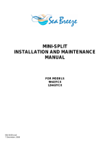
NOTE: After installation, the pressure reading should be as indicated below. Take from the service port, the
pressure under the outdoor temperature should match the charts readings.
Cooling chart:
COOLING MODE
Outdoor Temp >
Indoor Temp v
75°F
85°F
95°F
105°F
115°F
70°F
119.0
113.0
117.0
125.0
147.0
PSI
75°F
124.0
120.0
126.0
132.0
155.0
PSI
80°F
135.0
129.0
132.0
140.0
162.0
PSI
Pressure (PSI)
Outdoor Temperature
It is recommended to record and charge when the outdoor temperature is within the chart temperatures.

950-0211revA - 16 - March 7, 2014
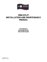
Heating Chart:
HEATING MODE
Outdoor Temp >
Indoor Temp v
57°F
47°F
37°F
27°F
17°F
55°F
439.0
413.0
367.0
330.0
302.0
PSI
65°F
471.0
435.0
386.0
368.0
339.0
PSI
75°F
489.0
457.0
403.0
381.0
362.0
PSI
Pressure (PSI)
Outdoor Temperature
It is recommended to record and charge when the outdoor temperature is within the chart temperatures.

950-0211revA - 17 - March 7, 2014
TECHNICAL SPECIFICATIONS FOR 9000 BTU AC AND HP (115V)
(Thermal Zone - Sea Breeze) Indoor / Outdoor
244-1201-E, 244-1201-C
9A45YIMI, 9A45YOMI
244-1301-E, 244-1301-C
9H45YIMI, 9H45YOMI
Power supply
PH-V-Hz
1Ph,115V~, 60Hz
1Ph,115V~, 60Hz
Max. current / Breaker size / Min. circuit ampacity
A
15/20/19
16/20/19
Starting current
A
---
---
Cooling
Capacity
BTU/H
9000
9000
Input
W
1000
1000
Rated current
A
8.9
8.9
SEER
BTU/WH
15.0
15.0
EER
BTU/WH
9.0
9.0
Heating
Capacity
BTU/H
-----
9000
Input
W
-----
890
Rated current
A
-----
7.9
HSPF / COP
-----
8.2 / 3.2
Moisture Removal
PNTS/H
2.2
2.2
Compressor
Model
DA108X1C-23EZ
DA108X1C-23EZ
Type
ROTARY
ROTARY
Brand
GMCC
GMCC
Capacity
BTU/H
11021
11021
Input
W
855
855
Rated current(RLA)
A
4.95
4.95
Locked rotor Amp(LRA)
A
---
---
Thermal protector
---
---
Thermal protector position
---
---
Capacitor
uF
45
45
Refrigerant oil/oil charge
ml
ESTER OIL VG74 480 ml
ESTER OIL VG74 480 ml
Indoor fan motor
Model
RPG15A
RPG15A
Brand
Welling
Welling
Input
W
46
46
Capacitor
uF
3.0
3.0
Speed(H/M/L)
RPM
1200/1050/800
1200/1050/850
Indoor air flow (H/M/L)
CFM
480/420/320
480/420/320
Indoor noise level (H/M/L)
dB(A)
39/35/28
39/35/28
Indoor unit
Dimension(W*D*H)
IN
26.77x7.01x10.04
26.77x7.01x10.04
Packing (W*D*H)
IN
29.33x10.04x12.99
29.33x10.04x12.99
Net/Gross weight
LB
15.43/17.64
15.43/17.64
Outdoor fan motor
Model
YDK24-6AS
YDK24-6AS
Brand
Welling
Welling
Input
W
64/47
64/47
Capacitor
uF
3.0
3.0
Speed
RPM
860/ --- /660
860/ --- /660
Outdoor air flow
CFM
824
824
Outdoor noise level
dB(A)
54
56
Outdoor unit
Dimension(W*D*H)
IN
25.98x10.43x21.26
25.98x10.43x21.26
Packing (W*D*H)
IN
31.10x13.98x24.41
31.10x13.98x24.41
Net/Gross weight
IN
62.83/69.45
63.93/70.55
Refrigerant type
oz.
R410A /31.8
R410A / 31.8
Design pressure
PSIG
550/340
550/340
Refrigerant piping
Liquid side/ Suction side
IN
1/4" / 3/8"
1/4" / 3/8"
Max. refrigerant pipe length
FT
82
82
Maximum vertical height
FT
33
33
Design length
FT
25
25
Extra Refrigerant charge above
design length
OZ/FT
0.161
0.161
Remote Control
YES
YES
Electrical Shock Protection
I
I
Indoor selection range - remote
°F
62°F to 86°F
62°F to 86°F
Outdoor operating range (cool/heat) w/LoAmbientKit
°F
5~122°F
5~122°F / 5~86°F

950-0211revA - 18 - March 7, 2014
TECHNICAL SPECIFICATIONS FOR 12000 BTU AC AND HP (115V)
(Thermal Zone - Sea Breeze) Indoor / Outdoor
244-1202-E, 244-1202-C
12A45YIMI, 12A45YOMI
244-1302-E, 244-1302-C
12H45YIMI, 12H45YOMI
Power supply
PH-V-Hz
1Ph,115V~, 60Hz
1Ph,115V~, 60Hz
Max. current / Breaker size / Min. circuit ampacity
A
15/20/20
16/20/20
Starting current
A
---
---
Cooling
Capacity
BTU/H
12000
12000
Input
W
1330
1340
Rated current
A
11.8
11.9
SEER
BTU/WH
15.0
15.0
EER
BTU/WH
9.0
9.0
Heating
Capacity
BTU/H
-----
12000
Input
W
-----
1320
Rated current
A
-----
11.7
HSPF / COP
-----
8.2 /3.2
Moisture Removal
PNTS/H
2.6
2.6
Compressor
Model
DA108X1C-23EZ
DA108X1C-23EZ
Type
ROTARY
ROTARY
Brand
GMCC
GMCC
Capacity
BTU/H
11021
11021
Input
W
855
855
Rated current(RLA)
A
4.95
4.95
Locked rotor Amp(LRA)
A
---
---
Thermal protector
---
---
Thermal protector position
---
---
Capacitor
uF
45
45
Refrigerant oil/oil charge
Ml
ESTER OIL VG74 480 ml
ESTER OIL VG74 480 ml
Indoor fan motor
Model
RPG15A
RPG15A
Brand
Welling
Welling
Input
W
46
46
Capacitor
uF
3.0
3.0
Speed(H/M/L)
RPM
1200/1050/800
1200/1050/800
Indoor air flow (H/M/L)
CFM
580/500/400
580/500/400
Indoor noise level (H/M/L)
dB(A)
39/35/29
39/35/29
Indoor unit
Dimension(W*D*H)
IN
30.31X7.40X10.04
30.31X7.40X10.04
Packing (W*D*H)
IN
32.87X10.43X12.99
32.87X10.43X12.99
Net/Gross weight
LB
16.53/20.94
16.53/20.94
Outdoor fan motor
Model
YDK24-6AS
YDK24-6AS
Brand
Welling
Welling
Input
W
64/47
64/47
Capacitor
uF
3.0
3.0
Speed
RPM
860/---/660
860/---/660
Outdoor air flow
CFM
1400
1400
Outdoor noise level
dB(A)
55
55
Outdoor unit
Dimension(W*D*H)
IN
25.98X10.43X21.26
25.98X10.43X21.26
Packing (W*D*H)
IN
31.10X13.98X24.41
31.10X13.98X24.41
Net/Gross weight
IN
65.04/71.65
66.14/70.55
Refrigerant type
oz.
R410A / 31.8
R410A / 33.57
Design pressure
PSIG
550/340
550/340
Refrigerant piping
Liquid side/ Suction side
IN
1/4" / 1/2"
1/4" / 1/2"
Max. refrigerant pipe length
FT
82
82
Maximum vertical height
FT
33
33
Design length
FT
25
25
Extra Refrigerant charge above
design length
OZ/FT
0.161
0.161
Remote Control
YES
YES
Electrical Shock Protection
I
I
Indoor selection range - remote
°F
62~86 °F
62~86 °F
Outdoor operating range (cool/heat) w/LoAmbientKit
°F
5~122 °F
5~122 °F /5~86 °F

950-0211revA - 19 - March 7, 2014
TECHNICAL SPECIFICATIONS FOR 12000 BTU UNITS (208-230V)
(Thermal Zone - Sea Breeze) Indoor / Outdoor
244-1203-E, 244-1203-C
12A45ZIMI, 12A45ZOMI
244-1303-E, 244-1303-C
12H45ZIMI, 12H45ZOMI
Power supply
PH-V-Hz
1Ph,208/230V~,60Hz
1Ph,208/230V~,60Hz
Max. current / Breaker size / Min. circuit ampacity
A
8/15/10
8/15/10
Starting current
A
---
---
Cooling
Capacity
BTU/H
12000
12000
Input
W
1330
1320
Rated current
A
6
5.9
SEER
BTU/WH
15.0
15.0
EER
BTU/WH
9.0
9.0
Heating
Capacity
BTU/H
-----
12000
Input
W
-----
1220
Rated current
A
-----
5.5
HSPF / COP
-----
8.2 / 3
Moisture Removal
PNTS/H
2.6
2.6
Compressor
Model
DA108X1C-20FZ3
DA108X1C-23EZ
Type
ROTARY
ROTARY
Brand
GMCC
GMCC
Capacity
BTU/H
10918
11021
Input
W
855
855
Rated current(RLA)
A
5.3
4.95
Locked rotor Amp(LRA)
A
---
---
Thermal protector
INT01L-4639 / CS-74
---
Thermal protector position
EXTERNAL
---
Capacitor
uF
6.0
6.0
Refrigerant oil/oil charge
ml
ESTER OIL VG74 / 480
ESTER OIL VG74 / 480
Indoor fan motor
Model
RPG20B
RPG20B
Brand
Welling
Welling
Input
W
43
43
Capacitor
uF
1.5
1.5
Speed(H/M/L)
RPM
1200/1050/800
1200/1050/800
Indoor air flow (H/M/L)
CFM
600/530/400
600/530/400
Indoor noise level (H/M/L)
dB(A)
39/35/31
39/35/31
Indoor unit
Dimension(W*D*H)
IN
30.31X7.40X10.04
30.31X7.40X10.04
Packing (W*D*H)
IN
32.87X10.43X12.99
32.87X10.43X12.99
Net/Gross weight
LB
16.53/20.94
16.53/20.94
Outdoor fan motor
Model
YDK24-6GB
YDK24-6GB
Brand
Welling
Welling
Input
W
75/66
75/66
Capacitor
uF
2.6
2.5
Speed
RPM
940 / --- / 835
940 / --- / 835
Outdoor air flow
CFM
1900
1900
Outdoor noise level
dB(A)
55
57
Outdoor unit
Dimension(W*D*H)
IN
30.71X9.84X21.26
30.71X9.84X21.26
Packing (W*D*H)
IN
35.83X13.19X23.03
35.83X13.19X23.03
Net/Gross weight
IN
61.73/66.14
66.14/70.55
Refrigerant type
oz.
R410A / 22.93
R410A / 32.1
Design pressure
PSIG
550/340
550/340
Refrigerant piping
Liquid side/ Suction side
IN
1/4" / 3/8"
1/4" / 3/8"
Max. refrigerant pipe length
FT
82
82
Maximum vertical height
FT
33
33
Design length
FT
25
25
Extra Refrigerant charge above
design length
OZ/FT
0.161
0.161
Remote Control
YES
YES
Electrical Shock Protection
I
I
Indoor selection range - remote
°F
62~86 °F
62~86 °F
Outdoor operating range (cool/heat) w/LoAmbientKit
°F
5~122 °F
5~122 °F /5~86 °F
/