Majestic Trilliant Series Direct Vent Gas Insert Owner's manual
- Category
- Fireplaces
- Type
- Owner's manual
This manual is also suitable for

1
Majestic • TRILLIANT25IN, TRILLIANT30IN, TRILLIANT35IN Owner’s Manual • 2571-981 Rev. C • 10/23
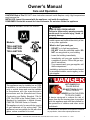
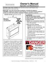
Owner’s Manual
Care and Operation
NOTICE: DO NOT discard this manual!
This appliance may be installed as an OEM
installation in manufactured home (USA
only) or mobile home and must be installed
in accordance with the manufacturer’s
instructions and the Manufactured Home
Construction and Safety Standard, Title 24
CFR, Part 3280 in the United States, or the
Standard for Installation in Mobile Homes,
CAN/CSA Z240 MH Series, in Canada.
This appliance is only for use with the type(s)
of gas indicated on the rating plate. This
appliance is not convertible for use with other
gases, unless a certied kit is used.
• DO NOT store or use gasoline or other am-
mable vapors and liquids in the vicinity of this
or any other appliance.
• What to do if you smell gas
- DO NOT try to light any appliance.
- DO NOT touch any electrical switch. DO
NOT use any phone in your building.
- Leave the building immediately.
- Immediately call your gas supplier from
a neighbor’s phone. Follow the gas sup-
plier’s instructions.
- If you cannot reach your gas supplier, call
the re department.
• Installation and service must be performed
by a qualied installer, service agency, or the
gas supplier.
WARNING:
FIRE OR EXPLOSION HAZARD
Failure to follow safety warnings exactly
could result in serious injury, death, or
property damage.
DANGER
HOT GLASS WILL
CAUSE BURNS.
DO NOT TOUCH GLASS
UNTIL COOLED.
NEVER ALLOW CHILDREN
TO TOUCH GLASS.
A barrier designed to reduce the risk of
burns from the hot viewing glass is provided
with this appliance and must be installed for
the protection of children and other at-risk
individuals.
Models:
TRILLIANT25IN
TRILLIANT30IN
TRILLIANT35IN
CAUTION! Risk of Fire! DO NOT store instruction manuals inside replace cavity. High temperatures
could cause a re.
INSTALLER: Leave this manual with the appliance, not inside the appliance.
CONSUMER: Retain this manual for future reference. Do not store inside the appliance
Pour demander un exemplaire en français de ce Manuel
du propriétaire, visitez www.majesticproducts.com.

2Majestic • TRILLIANT25IN, TRILLIANT30IN, TRILLIANT35IN Owner’s Manual • 2571-981 Rev. C • 10/23
Read this manual before operating this appliance.
Please retain this Owner’s Manual for future reference.
Read the Installation Manual before making any installation or nishing changes.
1 1 Welcome
A. Congratulations
Congratulations on selecting a Majestic gas replace, an
elegant and clean alternative to wood burning replaces.
The Majestic gas replace you have selected is designed
to provide the utmost in safety, reliability, and efciency.
As the owner of a new replace, you’ll want to read and
carefully follow all of the instructions contained in this
Owner’s Manual. Pay special attention to all cautions and
warnings.
This Owner’s Manual should be retained for future
reference. We suggest that you keep it with your other
important documents and product manuals.
The information contained in this Owner’s Manual, unless
noted otherwise, applies to all models and gas control
systems.
Your new Majestic gas replace will give you years of
durable use and trouble-free enjoyment. Welcome to the
Majestic family of replace products!
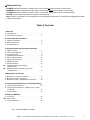
Listing Label Information/Location
Model Name: ___________________________________________ Date purchased/installed: __________________
Serial Number: __________________________________________ Location on replace: _____________________
Dealership purchased from: _______________________________ Dealer Phone: __________________________
Notes: _______________________________________________________________________________________
_____________________________________________________________________________________________
We recommend that you record the following pertinent
information about your replace.
Gas and Electric
Information
Serial Number
Type of Gas
Homeowner Reference Information
Model Number
Not for use with solid fuel.
(Ne doit pas entre utilise avec un combustible solide).
This appliance must be installed in accordance with local codes, if any; if not, follow ANSI Z223.1
in the USA or CAN/CGA B149 installation codes. (Installer l’appareil selon les codes ou reglements
locaux ou, en l’absence de tels reglements, selon les codes d’installation
Type of Gas (Sorte De Gaz):
NATURAL GAS
MADE MADE IN IN USAUSA
Minimum Minimum Permissible Permissible
Majestic, a brand of Hearth & Home Technologies
7571 215th Street West, Lakeville, MN 55044
Gas Gas Supply Supply for for Purposes Purposes of of Input Input Adjustment.Adjustment.
Approved Approved Minimum Minimum (De (De Gaz) Gaz) AcceptableAcceptable0.00.0 in in w.c.w.c. (Po. (Po. Col. Col. d’eau)d’eau)
Maximum Maximum Pressure Pressure (Pression)(Pression) 0.00.0 in in w.c.w.c. (Po. (Po. Col. Col. d’eau)d’eau)
Maximum Maximum Manifold Manifold Pressure Pressure (Pression)(Pression) 0.00.0 in in w.c.w.c. (Po. (Po. Col. Col. d’eau)d’eau)
Minimum Minimum Manifold Manifold Pressure Pressure (Pression)(Pression) 0.00.0 in in w.c.w.c. (Po. (Po. Col. Col. d’eau)d’eau)
Model:Model:
(Modele):(Modele):
SerialSerial
(Serie):(Serie):
ANSI Z21XX-XXXX · CSA 2.XX-MXX
XXXXXXXXXXXXXXXX
IN IN CANADACANADA
ALTITUDE:ALTITUDE:0-0000 0-0000 FT.FT.0000-0000FT.0000-0000FT.
MAX. MAX. INPUT INPUT BTUH:BTUH: 00,00000,000 00,00000,000
MIN. MIN. INPUT INPUT BTUH:BTUH: 00,00000,000 00,00000,000
ORIFICE ORIFICE SIZE:SIZE: #XXXXX#XXXXX #XXXXX#XXXXX XXXXXXXXXXXXXXXX
Total Total Electrical Electrical Requirements: Requirements: 000Vac, 000Vac, 00Hz., less than 00 Amperes
The model information regarding your specic replace can be found on
the rating plate usually located in the control area of the replace.

3
Majestic • TRILLIANT25IN, TRILLIANT30IN, TRILLIANT35IN Owner’s Manual • 2571-981 Rev. C • 10/23
Table of Contents
1 Welcome
A. Congratulations .................................2
B. Limited Lifetime Warranty ..........................4
2 Product Specic Information
A. Appliance Certication ............................6
B. Glass Specications .............................. 6
C. BTU Specications ............................... 6
3 Important Safety and Operating Information
A. Appliance Safety ................................7
B. General Operating Parts ..........................8
C. Fuel Specications ...............................8
D. Wall Surface/TV Guidelines ........................ 8
E. Before Lighting Appliance. . . . . . . . . . . . . . . . . . . . . . . . . 10
F. Lighting Instructions (IPI) ......................... 11
G. Appliance Break-In .............................. 12
H. Heat Management ..............................12
I. Operation During A Power Outage -
IntelliFire Touch® ...............................13
J. Detailed Component Operating Instructions
- IntelliFire Touch ...............................15
4 Maintenance and Service
A. Maintenance: Frequency and Tasks ................17
B. Maintenance Tasks - Homeowner ..................17
C. Maintenance Tasks - Qualied Service Technician .....20
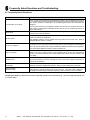
5 Frequently Asked Questions and Troubleshooting
A. Frequently Asked Questions ......................22
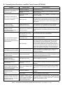
B. Frequently Asked Questions - IntelliFire Touch Controls
(IFT-RC400) ...................................23
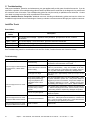
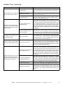
C. Troubleshooting ................................24
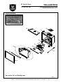
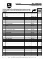
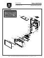
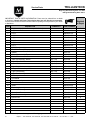
6 Reference Materials
A. Accessories ...................................26
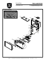
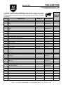
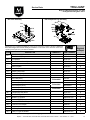
B. Service Parts ..................................27
C. Contact Information .............................35
= Contains updated information.
Safety Alert Key:
• DANGER! Indicates a hazardous situation which, if not avoided will result in death or serious injury.
• WARNING! Indicates a hazardous situation which, if not avoided could result in death or serious injury.
• CAUTION! Indicates a hazardous situation which, if not avoided, could result in minor or moderate injury.
• NOTICE: Used to address practices not related to personal injury.
Note: The term “recommend” or “recommended” does not indicate a requirement. It is a best practice suggested by Hearth
& Home Technologies®.

4Majestic • TRILLIANT25IN, TRILLIANT30IN, TRILLIANT35IN Owner’s Manual • 2571-981 Rev. C • 10/23
B. Limited Lifetime Warranty
Hearth & Home Technologies LLC
LIMITED LIFETIME WARRANTY
Hearth & Home Technologies LLC (“HHT”) extends the following warranty for HHT gas, wood, pellet and electric hearth appliances
(each a “Product” and collecvely, the “Product(s)”) and certain component parts set forth in the table below (“Component Part(s)”)
that are purchased from a HHT authorized dealer or distributor.
WARRANTY COVERAGE:
HHT warrants that the Products and their Component Parts will be free from defects in materials and workmanship for the applicable
period of Warranty coverage set forth in the table below (“Warranty Period”). If a Product or Component Parts are found to be
defecve in materials or workmanship during the applicable Warranty Period, HHT will, at its opon, repair the applicable Component
Part(s), replace the applicable Component Part(s), or refund the purchase price of the applicable Product(s). The maximum amount
recoverable under this Warranty is limited to the purchase price of the Product. This Warranty is transferable from the original purchaser
to subsequent owners, but the Warranty Period will not be extended in duraon or expanded in coverage for any such transfer. This
Warranty is subject to condions, exclusions, and limitaons as described below.
WARRANTY PERIOD:
Warranty coverage begins at the date of installaon. In the case of new home construcons, Warranty coverage begins on the date of
rst occupancy of the dwelling or six months aer the sale of the Product(s) by an independent, authorized HHT dealer or distributor,
whichever occurs earlier. However, the Warranty coverage shall commence no later than 24 months following the date of Product
shipment from HHT, regardless of the installaon or occupancy date.
The term “Lifeme” in the table below is dened as: 20 years from the beginning date of warranty coverage for gas appliances, 10 years
from the beginning date of warranty coverage for wood and pellet appliances, and 5 years from the beginning of warranty coverage
for standalone gas log sets. These me periods reect the minimum expected useful lives of the designated Component Parts under
normal operang condions.
Page 1 of 2
4021-645M 9/21
Component
Parts Labor Gas Pellet Wood Electric Venting Component Parts Covered by this Warranty
XAll parts except as covered by Warranty Conditions,
Warranty Exclusions, and Warranty Limitations listed
X X Igniters, Auger Motors, Electronic Components, and
Glass
X
Electrical components limited to modules, remotes/wall
switches, valves, pilots, blowers, junction boxes, wire
harnesses, transformers and lights (excluding light bulbs)
X X Molded Refractory Panels, Glass Liners
X
Burners and logs for standalone gas log sets
(Vented and Vent Free gas log sets not sold as
components of the fireplace or stove)
X
Vent Free Burners and Vent Free Log components of
HHT manufactured fireplaces or stoves
X X Castings, Medallions and Baffles
6 years 3 years XCatalysts
7 years 3 years X X Manifold tubes, HHT Chimney and Terminations
10 years 1 year X
Burners, logs and refractory components of HHT
manufactured fireplaces or stoves
Limited
Lifetime 3 years XXX Firebox and heat exchanger, FlexBurn® System
(engine, inner cover, access cover and fireback)
1 Year
None XXXXX All purchased replacement parts
Warranty Period HHT Manufactured Appliances and Venting
All parts including handles, external enameled
components and other material except as covered by
Warranty Conditions, Warranty Exclusions, and
Warranty Limitations listed
2 years
X
1 Year X X X
2 Years
5 years 1 year
Firepots, burnpots, mechanical feeders/auger
assemblies
3 years X
5 years

5
Majestic • TRILLIANT25IN, TRILLIANT30IN, TRILLIANT35IN Owner’s Manual • 2571-981 Rev. C • 10/23
WARRANTY CONDITIONS:
• Because HHT cannot control the quality of any Products sold by unauthorized sellers, this Warranty only covers Products that are
purchased through an HHT authorized dealer or distributor unless otherwise prohibited by law; a list of HHT authorized dealers
is available on the HHT branded websites.
• This Warranty is only valid while the applicable Product remains at the site of original installaon.
• This Warranty is only valid in the country in which the HHT authorized dealer or distributor that sold the applicable Product is
authorized to sell applicable Product.
• Contact your installing distributor or dealer for Warranty service. If the installing dealer or distributor is unable to provide
necessary parts, contact the nearest HHT authorized dealer or supplier. Addional service fees may apply if you are seeking
Warranty service from a dealer other than the dealer from whom you originally purchased the applicable Product.
• No HHT consumer should bear cost of warranty service or costs incurred while servicing warranty claims (i.e., travel, gas, or
mileage) when the service is performed within the terms of this Warranty. Check with your dealer or distributor in advance for
any costs to you when arranging a warranty call. Travel and shipping charges for parts are not covered by this Warranty.
WARRANTY EXCLUSIONS:
This Warranty does not cover the following:
• Changes in surface nishes as a result of normal use. As a heang appliance, some changes in color of interior and exterior surface
nishes may occur. This is not a aw and is not covered under the Warranty.
• Damage to printed, plated, or enameled surfaces caused by ngerprints, accidents, misuse, scratches, melted items or other
external sources and residues le on the plated surfaces from the use of abrasive cleaners or polishes.
• Repair or replacement of parts that are subject to normal wear and tear during the Warranty Period are not covered. These parts
include: paint, wood and pellet gaskets, rebricks, grates, ame guides, baeries and the discoloraon of glass.
• Minor expansion, contracon, or movement of certain parts causing noise. These condions are normal and complaints related to
this noise are not covered by this Warranty.
• Damages resulng from: (1) failure to install, operate, or maintain the applicable Product in accordance with the installaon
instrucons, operang instrucons, and lisng agent idencaon label furnished with the applicable Product; (2) failure to
install the applicable Product in accordance with local building codes; (3) shipping or improper handling; (4) improper operaon,
abuse, misuse, connued operaon with damaged, corroded or failed components, accident, or improperly/incorrectly performed
repairs; (5) environmental condions, inadequate venlaon, negave pressure, or draing caused by ghtly sealed construcons,
insucient make-up air supply, or handling devices such as exhaust fans or forced air furnaces or other such causes; (6) use of fuels
other than those specied in the operaon instrucons; (7) installaon or use of components not supplied with the applicable
Product or any other components not expressly authorized and approved by HHT; (8) modicaon of the appliance not expressly
authorized and approved by HHT in wring; and/or (9) interrupons or uctuaons of electrical power supply to the applicable
Product.
• Non-HHT venng components, hearth connecons or other accessories used in conjuncon with the applicable Product.
• Any part of a pre-exisng replace system in which an insert or a decorave gas applicable Product is installed.
• HHT’s obligaon under this Warranty does not extend to the Product’s capability to heat the desired space. Informaon is provided
to assist the consumer and the dealer in selecng the proper Product for the applicaon. Consideraon must be given to the
Product locaon and conguraon, environmental condions, insulaon and air ghtness of the structure.
This warranty is void if:
• The applicable Product has been over-red, operated in atmospheres contaminated by chlorine, uorine, or other damaging
chemicals. Over-ring can be idened by, but not limited to, warped plates or tubes, deformaon/warping of interior cast iron
structure or components, rust colored cast iron, bubbling, cracking and discoloraon of steel or enamel nishes.
• The applicable Product is subjected to prolonged periods of dampness or condensaon.
• There is any damage to the applicable Product due to water or weather damage which is the result of, but not limited to, improper
chimney or venng installaon.
LIMITATIONS OF REMEDIES AND LIABILITY:
• EXCEPT TO THE EXTENT PROVIDED BY LAW, HHT MAKES NO EXPRESS WARRANTIES OTHER THAN THE WARRANTY SPECIFIED
HEREIN. The owner’s exclusive remedy and HHT’s sole obligaon under this Warranty or in contract, tort or otherwise, shall be
limited to replacement of the Component Part(s), repair of the Component Part(s), or refund of the original purchase price of the
applicable Product(s), as specied above; provided, however, that (i) if HHT is unable to provide replacement of the Component
Part(s) and repair of the Component Part(s) is not commercially praccable or cannot be mely made, or (ii) the customer is
willing to accept a refund of the purchase price of the applicable Product(s), HHT may discharge all such obligaons by refunding
the purchase price of the applicable Product. In no event will HHT be liable for any incidental or consequenal damages caused
by defects in the applicable Product. Some States do not allow the exclusion or limitaon of incidental or consequenal damages,
so the above limitaon or exclusion may not apply to you. This Warranty gives you specic legal rights and you may also have
other rights which vary from State to State. THE DURATION OF ANY IMPLIED WARRANTY IS LIMITED TO DURATION OF THE
EXPRESSED WARRANTY SPECIFIED ABOVE FOR THE APPLICABLE PRODUCT. Some States do not allow limitaons on how long an
implied warranty lasts, so the above limitaon may not apply to you.
Page 2 of 2
4021-645M 9/21

6Majestic • TRILLIANT25IN, TRILLIANT30IN, TRILLIANT35IN Owner’s Manual • 2571-981 Rev. C • 10/23
A. Appliance Certication
2 2 Product Specic Information
This product is listed to ANSI standards for “Vented Gas
Fireplace Heaters” and applicable sections of “Gas Burn-
ing Heating Appliances for Manufactured Homes and
Recreational Vehicles”, and “Gas Fired Appliances for
Use at High Altitudes”.
Gas inserts are designed for installations into solid fuel
masonry or factory built replaces that have been installed
in accordance with the National, Provincial, State and
local building codes. Fireplaces are to be constructed of
non-combustible materials and, in the absence of local or
regional codes, meet criteria of NFPA 211. No additional
outside air source is required.
NOT INTENDED FOR USE AS A PRIMARY HEAT SOURCE.
This appliance is tested and approved as either supplemen-
tal room heat or as a decorative appliance. It should not be
factored as primary heat in residential heating calculations.
NOTICE: This installation must conform with local codes.
In the absence of local codes you must comply with the
National Fuel Gas Code, ANSI Z223.1-latest edition in
the U.S.A. and the CAN/CGA B149 Installation Codes in
Canada.
B. Glass Specications
This appliance is equipped with ceramic glass. Replace
glass only with ceramic glass. Please contact your dealer
for replacement glass.
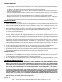
C. BTU Specications
MODELS: TRILLIANT25IN, TRILLIANT30IN,
TRILLIANT35IN
LABORATORY: Underwriters Laboratories, Inc. (UL)
TYPE: Direct Vent Heater
STANDARD: ANSI Z21.88-2019 CSA 2.33-2019
Models
(U.S. or Canada)
Maximum
Input
BTU/h
Minimum
Input
BTU/h
Orice
Size
(DMS)
TRILLIANT25IN
(NG) (0-2000 FT) 27,000 18,900 40
TRILLIANT25IN
(Propane) (0-2000 FT) 25,000 17,500 53
TRILLIANT30IN
(NG) (0-2000 FT) 32,700 22,890 35
TRILLIANT30IN
(Propane) (0-2000 FT) 32,000 22,400 51
TRILLIANT35IN
(NG) (0-2000 FT) 35,000 24,500 33
TRILLIANT35IN
(Propane) (0-2000 FT) 35,000 24,500 50
Installation and service of this appliance should be performed by
qualied personnel. Hearth & Home Technologies recommends
HHT Factory Trained or NFI certied professionals.

7
Majestic • TRILLIANT25IN, TRILLIANT30IN, TRILLIANT35IN Owner’s Manual • 2571-981 Rev. C • 10/23
WARNING! DO NOT operate replace before reading
and understanding operating instructions. Failure
to operate replace according to operating instructions
could cause re or injury.
Young children should be carefully supervised when they
are in the same room as the appliance. Toddlers, young
children and others may be susceptible to accidental
contact burns.
• A physical barrier is recommended if there are at risk
individuals in the house.
• To restrict access to a replace or stove, install an
adjustable safety gate to keep toddlers, young children
and other at risk individuals out of the room and away
from hot surfaces.
• Install a switch lock or a wall/remote control with child
protection lockout feature.
• Keep remote controls out of reach of children.
• Never leave children alone near a hot replace, whether
operating or cooling down.
A. Appliance Safety • Teach children to NEVER touch the replace.
• Consider not using the replace when children will be
present.
Contact your dealer for more information, or visit: www.
hpba.org/Product-Info/Fireplace-Stove-Heater/Glass-
Fronts-Safety.
To prevent unintended operation when not using your re-
place for an extended period of time (summer months,
vacations, trips, etc):
• Remove batteries from remote controls.
• Turn off wall controls.
• Set the selector switch on the control module to the off
position and remove batteries.
3 3 Important Safety and Operating Information
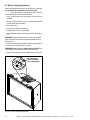
Clear Space
WARNING! DO NOT place combustible objects in front
of the replace or block louvers. High temperatures may
start a re. See Figure 3.1.
Avoid placing candles and other heat-sensitive objects on
mantel or hearth. Heat may damage these objects.
Figure 3.1 Clear Space Requirement - All Models
CLEAR SPACE
3 FT. IN
FRONT OF
FIREPLACE
A barrier designed to reduce the risk of burns from the
hot viewing glass is provided with this appliance and
must be installed for the protection of children and other
at-risk individuals. DO NOT operate the appliance with
the barrier removed. If the barrier becomes damaged,
the barrier must be replaced with the manufacturer’s
barrier for this appliance.
Contact your dealer or Hearth & Home Technologies if the
barrier is not present or help is needed to properly install one.
DANGER
HOT GLASS WILL
CAUSE BURNS.
DO NOT TOUCH GLASS
UNTIL COOLED.
NEVER ALLOW CHILDREN
TO TOUCH GLASS.
• Keep children away.
• CAREFULLY SUPERVISE children in same room
as replace.
• Alert children and adults to hazards of high
temperatures.
High temperatures may ignite clothing or other
ammable materials.
• Clothing, furniture, draperies, and other ammable
materials must not be placed on or near the
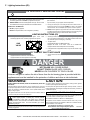
appliance.
WARNING: This product and the fuels used to
operate this product (liquid propane or natural
gas), and the products of combustion of such fuels, can
expose you to chemicals including benzene, which is
known to the State of California to cause cancer and
reproductive harm. For more information go to: www.
P65Warnings.ca.gov.

8Majestic • TRILLIANT25IN, TRILLIANT30IN, TRILLIANT35IN Owner’s Manual • 2571-981 Rev. C • 10/23
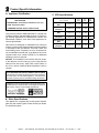
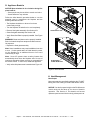
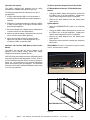
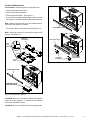
Figure 3.2 General Operating Parts
B. General Operating Parts
C. Fuel Specications
Figure 3.2 references the general operating parts of the
appliance and the section of this manual in which they are
discussed.
WARNING! Risk of Fire or Explosion! Appliance must
be set up for compatible gas type!
• This appliance is designed to operate on either natural
gas or propane. Make sure the appliance is compatible
with gas type selected for installation site.
• Conversions must be made by a qualified service
technician using Hearth & Home Technologies specied
and approved parts.
D. Wall Surface/TV Guidelines
DECORATIVE FRONTS
(NOT SHOWN)
SECTION 4.B
MANTEL
FIXED GLASS ASSEMBLY
SECTION 4.B
HEARTH
CLEAR SPACE
SECTION 3.A.
ACCESS TO
BATTERY BACKUP
SECTION 3.I
FAN KIT
SECTION 3.H & 3.J
REMOTE CONTROL
SECTION 6.C
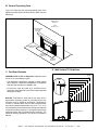
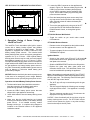
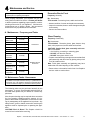
Figure 3.3 Good Faith Wall Surface Temperatures Above Appliance
NOTICE: Temperatures listed above are taken with a
temperature measuring probe as prescribed by the test
standard used for appliance certication. Temperatures
on walls or mantels taken with an infrared thermometer
may yield increased temperatures of up to 30 °F (17 °C) or
more depending on the thermometer settings and material
characteristics being measured. Use appropriate nishing
materials that are able to withstand these conditions. For
additional nishing guidelines, see Section 8 Installation
Manual.
MEASUREMENTS FROM TOP
OF THE SURROUND OPENING
CEILING
APPLIANCE SURROUND
SURROUND
OPENING
18 IN.
22 IN.
16 IN.
12 IN.
24 IN.
28 IN.
34 IN.
40 IN.
46 IN.
52 IN.
151 ºF
138 ºF
135 ºF
127 ºF
125 ºF
120 ºF
115 ºF
110 ºF
108 ºF
106 ºF

9
Majestic • TRILLIANT25IN, TRILLIANT30IN, TRILLIANT35IN Owner’s Manual • 2571-981 Rev. C • 10/23
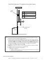
Item Minimum Dimensions
A 2.5 inches
B 2 inches minimum to 3 inches
maximum
C 24 inches
D Wall Brkt + TV Thickness + 2.5
inches
B
Fireplace
TV
Mantel
A
C
TV Wall
Bracket
D
TV on the wall
Notes:
1. These are good faith recommended clearances only and not a guarantee of compliance with all TV
manufacturers’ maximum allowable opera ng temperatures.
2. Since every home has unique air ow characteris cs and maximum allowable opera ng temperatures
can vary from manufacturer to manufacturer and from model to model, actual TV temperatures should
be validated at the me of each installa on. TVs should not be used in situa ons where the actual TV
temperature exceeds the manufacturers’ maximum allowable opera ng temperatures iden ed in the
TV’s technical specica ons. Contact the TV’s manufacturer directly if you cannot locate this
informa on or have ques ons regarding the informa on.
3. Mantel height and depth must conform to mantle requirements specified in the replace installa on
manual.
4.
“C” dimension taken from the top of the hood or fireplace opening.
5.
Sugges ons on how to further reduce TV temperatures:
a. Increase “A” dimension.
b.
Increase “C” dimension, however, increasing “B” dimension beyond maximum recommended
typically results in higher temperatures.
Good Faith Guidelines for TV Installations above a Gas Fireplace
Top of Surround
Opening
Figure 3.4 Good Faith TV Guidelines

10 Majestic • TRILLIANT25IN, TRILLIANT30IN, TRILLIANT35IN Owner’s Manual • 2571-981 Rev. C • 10/23
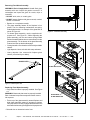
E. Before Lighting Appliance
Before operating this replace for the rst time, it is rec-
ommended that a qualied service technician:
• Verify all shipping materials have been removed
from inside and/or underneath the rebox.
• Verify multi-purpose tool has been removed and is
available.
• Review proper placement of logs, ember material and/
or other decorative materials.
• Check the wiring.
• Check the air shutter adjustment.
• Ensure that there are no gas leaks.
• Verify Glass Seal Plate is properly installed. See Figure
3.6.
WARNING! Glass seal plate must be properly installed.
Risk of elevated component temps and carbon monox-
ide exposure.
• Ensure that the glass is sealed and in the proper position
and that the integral barrier is in place.
WARNING! Risk of Fire or Asphyxiation! DO NOT op-
erate replace with xed glass assembly removed.
• Verify collar slide plate screw is attached see Figure 3.5.
Figure 3.5 Collar slide Plate Screw Detail
BE SURE SLIDE
PLATE SCREW IS
FULLY TIGHTENED.

11
Majestic • TRILLIANT25IN, TRILLIANT30IN, TRILLIANT35IN Owner’s Manual • 2571-981 Rev. C • 10/23
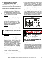
F. Lighting Instructions (IPI)
FOR YOUR SAFETY READ BEFORE LIGHTING
TO TURN OFF GAS TO APPLIANCE
1. This appliance is equipped with an ignition device which
automatically lights the burner. DO NOT try to light the burner by hand.
1. Equipped with wall switch: Turn ON/OFF switch to OFF.
Equipped with remote or wall control: Press OFF button.
Equipped with thermostat: Set temperature to lowest setting.
WARNING: If you do not follow these instructions exactly, a re or explosion may result causing property damage, personal injury or loss of life.
WARNING:
NOT FOR USE WITH SOLID FUEL
GAS
VALVE
For additional information on operating your
Hearth & Home Technologies replace, please
refer to www.hearthnhome.com.
A. This appliance is equipped with an intermittent pilot ignition (IPI) device which
automatically lights the burner. DO NOT try to light the burner by hand.
B. BEFORE LIGHTING, smell all around the appliance area for gas. Be sure to smell
next to the oor because some gas is heavier than air and will settle on the oor.
WHAT TO DO IF YOU SMELL GAS
• DO NOT try to light any appliance.
• DO NOT touch any electric switch; do not use any phone in your building.
DO NOT CONNECT LINE VOLTAGE (110/120 VAC OR 220/240 VAC) TO THE CON-
TROL VALVE.
Improper installation, adjustment, alteration, service or maintenance can cause injury
or property damage. Refer to the owner’s information manual provided with this ap-
pliance. For assistance or additional information, consult a qualied installer, service
agency or the gas supplier.
This appliance needs fresh air for safe operation and must be installed so there are
provisions for adequate combustion and ventilation air.
Hot while in operation. DO NOT touch. Keep children, clothing, furniture, gasoline
and other liquids having ammable vapors away.
DO NOT operate the appliance with xed glass assembly removed, cracked or
broken. Replacement of the xed glass assembly should be done by a licensed or
qualied service person.
• Immediately call your gas supplier from a neighbor’s phone. Follow the gas sup-
plier’s instructions.
• If you cannot reach your gas supplier, call the re department.
C. Use only your hand to push in or turn the gas control knob. Never use tools. If
the knob will not push in or turn by hand, DO NOT try to repair it, call a qualied
service technician. Force or attempted repair may result in a re or explosion.
D. DO NOT use this appliance if any part has been under water. Immediately call
a qualied service technician to inspect the appliance and to replace any part of
the control system and any gas control which has been under water.
For use with natural gas and propane. A conversion kit, as supplied by the manufac-
turer, shall be used to convert this appliance to the alternate fuel.
Also Certied for Installation in a Bedroom or a Bedsitting Room.
This appliance must be installed in accordance with local codes, if any; if none,
follow the National Fuel Gas Code, ANSIZ223.1/ NFPA 54, or the National Gas and
Propane Installation code, CSA B149.1.
LIGHTING INSTRUCTIONS (IPI)
2. Wait ve (5) minutes to clear out any gas. Then smell for gas, including near the
oor. If you smell gas, STOP! Follow “B” in the Safety Information located on the
top of this label. If you do not smell gas, go to next step.
3. To light the burner:
Equipped with wall switch: Turn ON/OFF switch to ON.
Equipped with remote or wall control: Press ON or FLAME button.
Equipped with thermostat: Set temperature to desired setting.
4. If the appliance does not light after three tries, call your service technician or gas
supplier.
2. Service technician should turn off electric power to the control when performing
service.
DANGER
HOT GLASS WILL CAUSE BURNS.
DO NOT TOUCH GLASS UNTIL COOLED.
NEVER ALLOW CHILDREN TO TOUCH GLASS.
CAUTION:
A barrier designed to reduce the risk of burns from the hot viewing glass is provided with this
appliance and must be installed for the protection of children and other at-risk individuals.
593-913K
WARNING: This product and the fuels used to operate this
product (liquid propane or natural gas), and the products
of combustion of such fuels, can expose you to chemicals
including benzene, which is known to the State of California to cause
cancer and reproductive harm. For more information go to: www.
P65Warnings.ca.gov.
Keep burner and control compartment clean. See installation and operating instructions
accompanying appliance.

12 Majestic • TRILLIANT25IN, TRILLIANT30IN, TRILLIANT35IN Owner’s Manual • 2571-981 Rev. C • 10/23
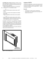
Figure 3.6 Glass Seal Plate
GLASS SEAL PLATE
GLASS SEAL
PLATE INSTALLED
H. Heat Management
Heat Output
Heat output may be controlled by adjusting the “FLAME”
setting and “FAN” setting on the RC-400 remote control.
NOTICE! Set the fan speed to high on the RC400 remote
control during the rst three to four hours of break-in
operation. See Section G. This break-in will ensure
optimum speed control of the fan during subsequent use.
G. Appliance Break-In
NOTICE! Open windows for air circulation during re-
place break-in.
• Some people may be sensitive to smoke and odors.
• Smoke detectors may activate.
Follow the initial break-in procedure below to cure the
materials used to manufacture the replace and the
nishing materials around it.
• The replace should be run three to four hours
continuously on high.
• Turn the replace off and allow it to cool completely.
• Remove xed glass assembly. See Section 4.B.
• Clean xed glass assembly. See Section 4.B.
• Verify Glass Seal Plate is properly installed. See Figure
3.6.
WARNING! Glass seal plate must be properly installed.
Risk of elevated component temps and carbon monox-
ide exposure.
• Replace the xed glass assembly.
Note: Some installations may require additional run time
to cure. If odors persist after the initial break-in period,
run the replace for an additional three to four hours
continuously on high.
Note: Some IPI systems have a safety feature that
automatically shuts down the replace after 9 hours of
continuous operation without receiving a command from
the remote control. If this occurs, restart the appliance.
• Verify collar slide plate screw is attached see Figure 3.5.

13
Majestic • TRILLIANT25IN, TRILLIANT30IN, TRILLIANT35IN Owner’s Manual • 2571-981 Rev. C • 10/23
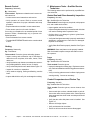
Figure 3.7 Control Cavity
SEE SECTION 4 FOR COMPONENT ACCESS DETAILS. 5. Locate the USB-C connector on the appliance as
shown in Figure 3.8. Remove rubber plug from the
USB-C port and insert the battery backup power
source USB-C connector into the appliance USB-
C port. Save USB-C rubber plug for reusing after
power has been restored.
6. Place the battery backup power source away from
any heat source and hot surface to the extent pos-
sible. Excessive heat will reduce the battery life.
See Figure 3.9.
7. Turn on the gas appliance by using one of the IFT
control devices, RC150 Wireless Wall Switch or
RC400 Remote Control, or through the Ignition
Module.
The IntelliFire Touch intermittent pilot ignition system
comes with a battery backup system that enables
the system to operate in a power outage. This gas
appliance is equipped with a USB-C connector to use
battery backup power sources. The included 4xAA
battery backup power source can support gas appliance
operation for up to 72 hours. Other optional battery
backup power sources may be used, and could support
gas appliance operation for up to 172 hours ( 7 days).
The optional battery backup power sources will require a
single cable that has USB-C male connectors to connect
the gas appliance to a battery backup power source or
any other commercially available battery power sources
such as laptops or Lithium-Ion based battery pack
(power bank) chargers.
NOTICE: Batteries should only be used as a power source
in the event of an emergency power outage. Batteries
should not be used as a primary long-term power source.
I. Operation During A Power Outage -
IntelliFire Touch®
IFT-RC150 Wireless Wall Switch:
• Toggle the switch as you would under normal
circumstances.
Ignition Module:
• Access to the control cavity (Figure 3.7) will require
the decorative barrier front, glass panel and the glass
seal plate to be removed.
• Slide the ON/REMOTE/OFF switch to the ON position.
• Replace the glass seal plate, glass panel and
decorative barrier front. The decorative barrier front
must be installed while operating the appliance.
Note: If the appliance is equipped with Wi-Fi, the IFT-Wi-Fi
app will not be available to control the gas appliance during
the AC power loss. The following events will take place
from the Wi-Fi app control device.
• The Wi-Fi app will stop communicating with the gas
appliance.
• The Wi-Fi app will display the following error message
on the app device screen: “Your appliance is currently
ofine”.
• The error message may take up to 5-10 minutes to be
displayed on the app device screen.
NOTICE: Some functionality will be lost when using the
battery backup power source. The IFT-RC400 remote
control will not operate fan, lights, or any other auxiliary
functions that require the AC power.
IFT-RC400 Wireless Remote:
• Remote receiver is integrated into the ignition module
• Use the remote to turn the appliance on.
• To preserve battery life, do not use the HI/LO ame or
THERMOSTAT options.
Operation with 4xAA Battery Backup Power Source:
1. The decorative barrier front should be removed to
ease the connection of the battery pack and re-
placed during operation of the appliance.
2. Locate the USB-C battery power source that was
shipped in the gas appliance manual bag.
3. Insert 4xAA batteries into the battery backup power
source.
4. Make sure that the 4xAA batteries are inserted
matching the indicators shown on the battery backup
power source. If not installed correctly, module
damage could occur. A complete wiring diagram is
included in the Electrical section of the appliance
installation manual.

14 Majestic • TRILLIANT25IN, TRILLIANT30IN, TRILLIANT35IN Owner’s Manual • 2571-981 Rev. C • 10/23
Operation with Laptop:
The USB-C equipped gas appliance can be easily
operated from a laptop during an AC power loss.
The following steps should be followed to turn on the
gas appliance.
1. A single cable that has USB-C male connectors or
an older version USB cable with suitable adapter is
required.
2. Establish a connection between the USB port (USB-C
or older version USB) of the laptop and the USB-C
port of the gas appliance.
3. The power settings of the laptop may be readjusted to
increase runtime from the laptop battery.
4. Make sure that the laptop is kept away from any heat
source and hot surface while operating.
5. When the AC power is restored, disconnect the
laptop from the USB-C of the gas appliance by re-
moving the USB-C connection cable.
Operation with Portable USB Battery Packs (Power
Banks):
The USB-C port can also be used to operate a gas
appliance from portable battery packs that charge
smartphones and other portable devices.
NOTICE: Some power banks and many USB battery packs
may switch off if the current being drawn is too low. IF this is
the case, different low power devices such as a cell phone,
laptop, etc. can be attached to the portable USB battery
packs while operating the gas appliance. Any additional
load may work to keep a portable USB battery pack active
to run the gas appliance.
To Return Operation Using Electrical (AC) Power:
IFT-RC400 Wireless Remote, IFT-RC400 Wireless
Remote:
• Unplug the USB-C battery backup power source from
the USB-C port of the gas appliance. Replace the
USB-C rubber plug back into port on appliance.
• Remove the 4xAA batteries from the battery pack
power source.
Ignition Module:
• Slide the ON/REMOTE/OFF switch to the Remote
position.
• Unplug the USB-C battery backup power source from
the USB-C port of the gas appliance. Replace the
USB-C rubber plug back into port on appliance.
• Remove the 4xAA batteries from the battery pack
power source.
• Replace any items removed, including the decorative
barrier front..
DISCLAIMER: This port is not a power input port or power
source. No data input or output.
Figure 3.8
USB CONNECTION
CONTROLS CAVITY
HEARTH
BATTERY BACKUP
Figure 3.9

15
Majestic • TRILLIANT25IN, TRILLIANT30IN, TRILLIANT35IN Owner’s Manual • 2571-981 Rev. C • 10/23
1. The Electronic Control Module (IFT-ECM) has a
three-position ON/OFF/REMOTE selector switch
that must be set for proper operation. See Figure
3.10. When changing switch positions,it is important
to pause in each position for 1-2 seconds.
OFF Position:
The appliance will not respond to any commands
from a wired wall switch, IFT-RC150 or IFT-RC400
remote controls. The unit should be in the OFF
position during installation, service, backup battery
installation, fuel conversion and to reset the IFT-
ECM in the event the system goes into a LOCK-
OUT mode as the result of a system error. When
switched to the OFF position while the appliance is
operating, the system will shut down.
ON Position:
The appliance will ignite and run continuously at
the HI ame setting. No adjustment in ame height
is possible.
Remote Position:
The remote position allows operation of the
appliance from a wired wall switch, IFT-RC400 or
IFT-RC150 remote controls. The IFT-ECM switch
must be in this position to pair the IFT-ECM with the
IFT-ACM (if installed), and/or IFT-RC400 and IFT-
RC150 remote controls. See the IFT-RC400 or IFT-
RC150 installation manual for detailed instructions
on pairing the IFT-ECM with the remote controls.
After successfully pairing a IFT-RC400, all installed
accessories can be controlled by the IFT-RC400
(see IFT-RC400 user manual). The RC150 allows
the user to turn ON/OFF the ame in the appliance
and activate the Cold Climate mode if desired. The
IFT-ECM has a safety feature that will automatically
shut down the replace after 9 hours of continuous
operation without receiving a command from the
IFT-RC400, IFT-RC150 or wired wall switch.
2. If multiple control options are installed, the IFT-ECM
will respond to the last command from the wired wall
switch, IFT-RC400 or IFT-RC150.
J. Detailed Component Operating
Instructions - IntelliFire Touch
IFT-ECM Detailed Operating Instruction
Figure 3.10 IFT-ECM
3 POSITION SWITCH
TOP VIEW
LED INDICATOR
DANGER
Risk of Explosion
DO NOT cycle the ON/OFF/REM selector
switch more than one time within a ve minute
period. Gas may accumulate in rebox. Call
a qualied service technician.
DANGER
Risk of Explosion
DO NOT cycle the ON/OFF/REM selector
switch more than one time within a ve minute
period. Gas may accumulate in rebox. Call
a qualied service technician.
4. An IFT-ECM reset is required if the module is in a
lock-out condition. When this occurs, the appliance
is shut down and the IFT-ECM status indicator LED
will be blinking a RED/GREEN error code along with a
one-time audible double- beep. If the IFT-ECM is in a
lock-out condition, refer to the troubleshooting chart to
interpret the error code and take corrective action as
required. To reset the IFT-ECM after a lock-out error:
3. The Pilot button on the IFT-ECM activates the Cold
Climate function of the fireplace. This function
lights the pilot ame ONLY to provide enough heat
in the rebox to reduce condensation in cool, high
humidity ambient conditions. To activate the Cold
Climate press and hold the Pilot button for one
second and release. The IFT-ECM will ash two
green LED blinks, beep twice and light and rectify
the pilot flame. To turn off Cold Climate, press
and hold the Pilot button for one second and release.
The IFT-ECM will ash one green LED blink, beep
once and shut down the pilot ame. If remote controls
are paired with the IFT-ECM, this feature can also be
activated with the IFT-RC400 and/or IFT-RC150.
This model is shipped from the factory equipped with the
IFT-RC400 remote.
SEE SECTION 4 FOR COMPONENT ACCESS DETAILS.
The IFT-ECM has a safety feature that will
automatically shut down the replace after 9 hours
of continuous operation in the ON position, except
when operated in active thermostat mode.

16 Majestic • TRILLIANT25IN, TRILLIANT30IN, TRILLIANT35IN Owner’s Manual • 2571-981 Rev. C • 10/23
CAUTION! Risk of burns! Appliance surfaces are hot
when operating and during cool down. Use care and
wear gloves when opening the front and accessing com-
ponents inside the appliance.
- Toggle the appliance reset switch to the off position.
See Figure 3.11 for reset switch location.
or
- Set the IFT-ECM 3-position selector switch to OFF
position.
- Wait ve (5) minutes to allow possible accumulated
gas to clear.
- Toggle the appliance reset switch to the on position.
or
- Set the IFT-ECM 3-position selector switch to ON or
REMOTE position. Module will beep once and ash a
three GREEN LED code on successful startup.
If placed in ON position, the appliance will ignite
normally if the error condition was corrected.
If placed in IFT-REM position or reset switch used, use
the paired IFT-RC400, IFT-RC150 or wired wall switch
to start the appliance; appliance will ignite normally if the
error condition was corrected.
If the IFT-ECM re-enters the lock-out condition after these
steps, call your dealer for service.
Appliance ON/OFF:
A wall control, thermostat or remote control may be used
to control the ON/OFF function of the appliance. Follow
instructions included with the installed control. Contact
your dealer for details.
Fan Kit
• This appliance includes a factory installed fan.
• Fan functions are integrated into the included IFT-
RC400 remote control.
SURROUND
RESET SWITCH
Figure 3.11 Surround Reset Switch

17
Majestic • TRILLIANT25IN, TRILLIANT30IN, TRILLIANT35IN Owner’s Manual • 2571-981 Rev. C • 10/23
B. Maintenance Tasks - Homeowner
The following tasks may be performed annually by the
homeowner. If you are uncomfortable performing any of
the listed tasks, please call your dealer for a service ap-
pointment.
More frequent cleaning may be required due to excessive
lint from carpeting, bedding material, etcetera. It is im-
perative that control compartments, burners and circulat-
ing air passageways of the appliance be kept clean. Any
safety screen, guard, or barrier removed for servicing the
appliance must be replaced prior to operating the appli-
ance.
CAUTION! Risk of Burns! The replace should be
turned off and cooled before servicing.
Any safety screen or guard removed for servicing must be
replaced prior to operating the replace.
Installation and repair should be done by a qualied service
technician only. The appliance should be inspected before
use and at least annually by a professional service person.
4 4 Maintenance and Service
A. Maintenance: Frequency and Tasks
When properly maintained, your replace will give you
many years of trouble-free service. Contact your dealer
to answer questions regarding proper operation, trouble-
shooting and service for your appliance. Visit www.ma-
jesticproducts.com to locate a dealer. We recommend
annual service by a qualied service technician.
Glass Cleaning
Frequency: Seasonally
By: Homeowner
Tools Needed: Protective gloves, glass cleaner, drop
cloth, multi-purpose tool, and a stable work surface.
CAUTION! Handle xed glass assembly with care.
Glass is breakable.
• Avoid striking, scratching or slamming glass
• DO NOT use abrasive cleaners
• DO NOT clean glass while it is hot
• Prepare a work area large enough to accommodate xed
glass assembly and door frame by placing a drop cloth
on a at, stable surface.
Note: Fixed glass assembly and gasketing may have
residue that can stain carpeting or oor surfaces.
• Remove door or decorative barrier front from replace
and set aside on work surface.
Decorative Barrier Front
Frequency: Annually
By: Homeowner
Tools needed: Protective gloves, stable work surface
• Assess condition of screen and replace as necessary.
• Inspect for scratches, dents or other damage and repair
as necessary.
• Vacuum and dust surfaces.
Task Frequency To be completed by
Decorative
Barrier Front Annually
Homeowner
Glass Cleaning Seasonally
Control Access Seasonally
Remote Control Seasonally
Venting Seasonally
Gasket Seal
and Glass
Inspection
Annually
Qualied Service
Technician
Log Inspection Annually
Firebox
Inspection Annually
Control
Compartment &
rebox Top
Annually
Burner Ignition
& Operation Annually

18 Majestic • TRILLIANT25IN, TRILLIANT30IN, TRILLIANT35IN Owner’s Manual • 2571-981 Rev. C • 10/23
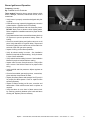
Removing Fixed Glass Assembly
WARNING! Risk of Asphyxiation! Handle xed glass
assembly with care. Inspect the gasket to ensure it is
undamaged and inspect the glass for cracks, chips or
scratches.
• DO NOT strike, slam, or scratch glass.
• DO NOT operate replace with glass removed, cracked,
broken or scratched.
• Replace as a complete assembly.
• The glass assembly fastens to the replace in four
places. The four fastening mechanisms are spring-
loaded glass latches. An example of the glass latch is
shown in Figure 4.2.
• To release glass assembly, use the supplied multi-
purpose tool. See Figure 4.1. While supporting the
glass assembly, pull the two bottom spring-loaded
latches forward and allow them to retract away from the
glass assembly. Tilt the bottom of the glass assembly
outward until the top latches disengage.
• Clean glass with a non-abrasive commercially available
cleaner.
- Light deposits: Use a soft cloth with soap and water.
- Heavy deposits: Use commercial fireplace glass
cleaner (consult with your dealer).
Figure 4.2. Fixed Glass Assembly
Figure 4.1 Multi-Purpose Tool
Replacing Fixed Glass Assembly
• Verify Glass Seal Plate is properly installed. See Figure
4.3.
WARNING! Glass seal plate must be properly installed.
Risk of elevated component temps and carbon monox-
ide exposure.
• Tilt the top of the glass assembly toward replace and
slide glass assembly upward to engage top latches.
Verify top latches are fully engaged and then fasten the
two bottom latches using the supplied multi-purpose tool.
• Reinstall door or decorative barrier front.
GLASS CLIPS
Figure 4.3 Glass Seal Plate
GLASS SEAL PLATE
GLASS SEAL
PLATE INSTALLED

19
Majestic • TRILLIANT25IN, TRILLIANT30IN, TRILLIANT35IN Owner’s Manual • 2571-981 Rev. C • 10/23
Control Cavity Access
Tools needed: Protective gloves, multi-purpose tool
• Remove decorative barrier front.
• Remove xed glass assembly.
• Remove glass seal plate. See Figure 4.3.
• For easier access, glass clip assemblies can be removed.
See Figure 4.5. Be careful when handling base refractory.
Figure 4.5 Glass Clip Removal
Figure 4.4 Component Tray Access
GLASS SEAL PLATE
BASE REFRACTORY
GLASS CLIP
ASSEMBLIES
GLASS
CLIP ASSEMBY
SCREW ACCESS
Note: Bottom right glass clip on 25 inch models must be
removed to gain access to controls.
GLASS SEAL PLATE
COMPONENT TRAY
WITH HEAT SHIELD
PRESS
TAB TO
RELEASE
UNCLIP
WIRES
COMPONENT
TRAY
COMPONENT
TRAY RECEIVER
Note: Wires may need to be removed from clips for full
access. See Figure 4.4.
• For access, slide out component tray. See Figure 4.4.
CAUTION: Be sure to reinstall the component heat shield
before ring the appliance. Components will overheat
without the heatshield in place.
CAUTION: Be sure to reinstall wires into the retaining clips.

20 Majestic • TRILLIANT25IN, TRILLIANT30IN, TRILLIANT35IN Owner’s Manual • 2571-981 Rev. C • 10/23
C. Maintenance Tasks - Qualied Service
Technician
The following tasks must be performed by a qualied ser-
vice technician.
Gasket Seal and Glass Assembly Inspection
Frequency: Annually
By: Qualied Service Technician
Tools needed: Protective gloves, drop cloth, multi-purpose
tool, and a stable work surface.
• Inspect gasket seal and its condition.
• Inspect xed glass assembly for scratches and nicks that
can lead to breakage when exposed to heat.
• Conrm there is no damage to glass or glass frame.
Replace as necessary.
• Verify that xed glass assembly is properly retained and
attachment components are intact and not damaged.
Replace as necessary.
• Verify Glass Seal Plate is properly installed. See Figure
4.3.
WARNING! Glass seal plate must be properly installed.
Risk of elevated component temps and carbon monox-
ide exposure.
Logs
Frequency: Annually
By: Qualied Service Technician
Tools needed: Protective gloves.
• Inspect for damaged or missing logs. Replace as neces-
sary. Refer to Installation manual for log placement instruc-
tions.
• Verify correct log placement and no ame impingement
causing sooting. Correct as necessary.
Venting
Frequency: Seasonally
By: Homeowner
Tools needed: Protective gloves and safety glasses.
• Inspect venting and termination cap for blockage or
obstruction such as plants, bird nests, leaves, snow,
debris, etc.
• Verify termination cap clearance to subsequent construc-
tion (building additions, decks, fences, or sheds).
• Verify collar slide plate screw is attached see Figure 3.5.
• Inspect for corrosion or separation.
• Verify weather stripping, sealing and ashing remains
intact.
• Inspect draft shield to verify it is not damaged or missing.
Remote Control
Frequency: Seasonally
By: Homeowner
Tools needed: Replacement batteries and remote con-
trol instructions.
• Locate remote control transmitter and receiver.
• Verify operation of remote. Refer to remote control
operation instructions for proper calibration and setup
procedure.
• Replace batteries as needed in remote transmitters.
• Place remote control out of reach of children.
If not using your replace for an extended period of time
(summer months, vacations/trips, etc), to prevent unin-
tended operation:
• Remove batteries from remote controls.
• Turn the ON/OFF/REMOTE switch on the control module
to OFF.
Control Compartment and Firebox Top
Frequency: Annually
By: Qualied Service Technician
Tools needed: Protective gloves, vacuum cleaner, dust
cloths
• Vacuum and wipe out dust, cobwebs, debris or pet hair.
Use caution when cleaning these areas. Screw tips that
have penetrated the sheet metal are sharp and should
be avoided.
• Verify that the collar slide plate screw is installed. See
Figure 3.5.
• Remove all foreign objects.
• Verify unobstructed air circulation.
• Ensure no wire connections become disengaged.
Page is loading ...
Page is loading ...
Page is loading ...
Page is loading ...
Page is loading ...
Page is loading ...
Page is loading ...
Page is loading ...
Page is loading ...
Page is loading ...
Page is loading ...
Page is loading ...
Page is loading ...
Page is loading ...
Page is loading ...
-
 1
1
-
 2
2
-
 3
3
-
 4
4
-
 5
5
-
 6
6
-
 7
7
-
 8
8
-
 9
9
-
 10
10
-
 11
11
-
 12
12
-
 13
13
-
 14
14
-
 15
15
-
 16
16
-
 17
17
-
 18
18
-
 19
19
-
 20
20
-
 21
21
-
 22
22
-
 23
23
-
 24
24
-
 25
25
-
 26
26
-
 27
27
-
 28
28
-
 29
29
-
 30
30
-
 31
31
-
 32
32
-
 33
33
-
 34
34
-
 35
35


Majestic Trilliant Series Direct Vent Gas Insert Owner's manual
- Category
- Fireplaces
- Type
- Owner's manual
- This manual is also suitable for
Ask a question and I''ll find the answer in the document
Finding information in a document is now easier with AI
Related papers
-
Majestic MERID42IL Gas Fireplace Owner's manual
-
-
Majestic MERC32IN User manual
-
Majestic Quartz Series Direct Vent Gas Fireplace Owner's manual
-
-
Majestic Meridian Owner's manual
-
-
-
-
Other documents
-
Majestic fireplaces MDVI30IN Owner's manual
-
 HEARTH HOME technologies DVLINEAR36 DV Linear Gas Fireplace Owner's manual
-
Heat & Glo Provident User manual
-
 HEARTH HOME technologies RCOR-DV36IN Direct Vent Gas Fireplace Owner's manual
-
-
-
-
-
HEARTH HOME IFT-RC150 IntelliFire Touch Wireless Wall Switch User manual
-

