Thermador PRD364WDHU Installation guide
- Category
- Cookers
- Type
- Installation guide

THERMADOR.COM
Installation
INSTRUCTIONS
Professional Series Pro Harmony
®
Ranges
Page is loading ...

THERMADOR.COM
Installation
INSTRUCTIONS
Models |
Modèles |
Modelos:
PRD304WHC/U
PRD305WHC/U
PRD364WDHC/U
PRD364WLHU
PRD366WHC/U
PRD484WCHU
PRD486WDHC/U
PRD486WLHU
PRG304WH
PRG305WH
PRG364WDH
PRG364WLH
PRG366WH
PRG486WDH
PRG486WLH
Table of contents (English)................................................................ 2
Table de matières (Français)............................................................ 26
Índice de materias (Español) ........................................................... 51
Professional Series Pro Harmony
®
Ranges

Page. 2
This THERMADOR
®
appliance is made by
BSH Home Appliances Corporation
1901 Main Street, Suite 600
Irvine, CA 92614
Questions?
1-800-735-4328
www.thermador.com
We look forward to hearing from you!
Table of
CONTENTS
Safety ...................................................................................... 3
Important safety instructions........................................... 3
Installation instructions .......................................................... 6
Planning information ....................................................... 6
Ventilation requirements ................................................ 6
Installation clearances...................................................... 7
Gas and electric locations ............................................... 12
Unpacking and moving the range .................................. 13
Installing the anti-tip bracket (required) ......................... 14
Gas requirements and hookup........................................ 15
Electrical requirements and connection for
GAS models..................................................................... 16
Electrical requirements and connection for
DUAL FUEL models ......................................................... 17
Backguard installation ..................................................... 19
Door removal and adjustment ........................................ 20
Placing and leveling the range........................................ 21
Data rating label.............................................................. 22
Burner test ...................................................................... 22
Installer checklist .................................................................... 25
Final check ....................................................................... 25
Support, accessories, and parts................................. back page
Safety
DEFINITIONS
9 WARNING
This indicates that death or serious injuries may occur as a
result of non-observance of this warning.
9 CAUTION
This indicates that minor or moderate injuries may occur as a
result of non-observance of this warning.
NOTICE: This indicates that damage to the appliance or
property may occur as a result of non-compliance with this
advisory.
Note: This alerts you to important information and/or tips.

Page. 3
Safety
9 IMPORTANT SAFETY INSTRUCTIONS
READ AND SAVE THESE INSTRUCTIONS
INSTALLER: Save these Instructions for the local gas
inspector’s use. Please leave these Installation instructions
with this unit for the owner. Show the owner the location
of the circuit breaker or fuse. Mark it for easy reference.
OWNER: Please retain these instructions for future
reference. Before using your appliance, be sure to read
this manual.
WARNING
ELECTRICAL SHOCK HAZARD
• Disconnect power before installing or
servicing. Before turning power ON, be sure
that all controls are in the OFF position.
• DO NOT remove connections.
• DO NOT use an extension cord.
• Improper grounding can result in a risk of
electric shock.
• Failure to follow these instructions can result
in death, fire, or electrical shock.
WARNING
RANGE TIPPING HAZARD:
• All ranges can tip and injury can result. To
prevent accidental tipping of the range,
attach it to the floor by installing the Anti-
Tip Bracket supplied.
• A risk of tip-over may exist if the appliance
is not installed in accordance with these
instructions. For all ranges an anti-tip device
MUST be installed.
• A child or adult can tip the range and be killed.
• DO NOT operate the range without the anti-tip
device in place and engaged. Failure to do so can
result in death or serious burns to children or adults.
• If the range is pulled away from
the wall for cleaning, service or
for any other reason, ensure that
the Anti-Tip Device is properly
re-engaged when the range is
pushed back against the wall. In the event of
abnormal usage (such as a person standing, sitting, or
leaning on an open door), failure to take this
precaution can result in tipping of the range. Personal
injury might result from spilled hot liquids or from the
range itself.
Local codes vary. Installer is responsible for ensuring that
the installation, gas connections, and grounding comply
with all applicable codes. Failure to follow appropriate
local codes and regulations may void the warranty.
The installation of appliances designed for manufactured
(mobile) home installation must conform with the
Manufactured Home Construction and Safety Standard,
Title 24 CFR, Part 3280 [formerly the Federal Standard for
Mobile Home Construction and Safety, Title 24, HUD {Part
280}] or with local codes where applicable.
The installation of appliances designed for Recreational
Park Trailers must conform with state or other codes or, in
the absence of such codes, with the Standard for
Recreational Park Trailers, ANSI A119.5.
Examine the appliance after unpacking it. In the event of
transport damage, do not plug it in.
WARNING
If the information in this manual is
not followed exactly, a fire or
explosion may result causing
property damage, personal injury or
death.
-- DO NOT store or use gasoline or other
flammable vapors and liquids in the
vicinity of this or any other appliance.
-- WHAT TO DO IF YOU SMELL GAS
• DO NOT try to light any appliance.
• DO NOT touch any electrical switch.
• DO NOT use any phone in your
building.
• Immediately call your gas supplier from
a neighbor’s phone. Follow the gas
supplier’s instructions.
• If you cannot reach your gas supplier,
call the fire department.
-- Installation and service must be
performed by a qualified installer, service
agency or the gas supplier.

Page. 4
9 IMPORTANT SAFETY INSTRUCTIONS
READ AND SAVE THESE INSTRUCTIONS
Remove all tape and packaging before using the
appliance. Dispose of packaging in an environmentally-
responsible manner. Never allow children to play with
packaging material.
This appliance must be grounded. Grounding reduces the
risk of electric shock by providing a safe pathway for
electric current in the event of a short circuit.
The appliance, when installed, must be electrically
grounded in accordance with local codes or, in the
absence of local codes, with the National Electrical Code,
NFPA 70 latest edition, or the Canadian Electric Code,
CSA C22.1-02.
DO NOT install this appliance outdoors.
For Massachusetts Installations:
• Installation must be performed by a qualified or
licensed contractor, plumber or gas fitter qualified or
licensed by the state, province or region where this
appliance is being installed.
• Shut-off valve must be a “T” handle gas cock.
• Flexible gas connector must not be longer than 36''
(914 mm).
Verify the type of gas supplied to the location. Ensure that
the appliance is connected to the type of gas for which it
is certified.
This appliance is capable of being safely placed in
operation in the event of a power failure. Only the
standard top burners can be manually lit.
Always keep appliance area clear from combustible
materials, gasoline and other flammable vapors and
liquids.
Natural gas — 7 inch water column. (17.4 mb) min., 14
inch (34.9 mb) maximum
Propane gas — 11 inch water column. (27.4 mb) min., 14
inch (34.9 mb) maximum
This appliance is shipped from the manufacturer for use
with natural gas. For use with propane (LP) gas, a
conversion kit must be purchased separately. An
authorized servicer must do the LP conversion. See the
back cover for information about service, parts, and
accessories.
CAUTION
When connecting the unit to propane gas, make certain
the propane gas tank is equipped with its own high-
pressure regulator in addition to the pressure regulator
supplied with the appliance. The maximum gas pressure
to this appliance must not exceed 14.0'' water column
(34.9 mb) from the propane gas tank to the pressure
regulator.
This appliance complies with one or more of the
following standards:
• UL 858, The Standard for the Safety of Household
Electric Ranges
• ANSI Z21.1, The American National Standard for
Household Cooking Gas Appliances
• CAN1-1.1-M81, Domestic Gas Ranges
• CSA C22.2 No. 61, Household Cooking Ranges
Check local building codes for the proper method of
appliance installation. Local codes vary; it is the
responsibility of the installer to ensure installation is in
accordance with these codes. Installation, electrical
connections, and grounding must comply with all
applicable codes.
In the absence of local codes the appliance should be
installed in accordance with the National Electric Code
NFPA 70 current issue and National Gas Code NFPA 54/
ANSI Z223.1 – current issue. In Canada, installation must
be in accordance with the Canadian Electric Code, CSA
C22.1-02 and the CAN 1-B149.1 and .2 – Installation
Codes for Gas Burning Appliances and/or local codes.
Proposition 65 Warning
This product may contain a chemical known to the State of
California, which can cause cancer or reproductive harm.
Therefore, the packaging of your product may bear the
following label as required by California:
State of California Proposition 65 Warning:
: WARNING
Cancer and Reproductive Harm -
www.P65Warnings.ca.gov

Page. 5
9 IMPORTANT SAFETY INSTRUCTIONS
READ AND SAVE THESE INSTRUCTIONS
REAR CLEARANCE REQUIREMENTS:
• To avoid staining on the back wall, high temperature,
non-porous construction materials suitable for use in a
cooking environment are recommended.
• Models PCG305xx, PRG305xx, PRG304xx, PRD305xx,
PRD304, and PRD606xx are suitable for 0'' rear
clearance to combustible surfaces.
• All other models:
• When using the included island trim a minimum 6"
(152 mm)* rear clearance is required to a
combustible surface*.
• When installing against a combustible surface, a
Thermador
®
low backguard is required for a 0''
rear clearance to the combustible surface. A
Thermador Low Backguard must be purchased
separately.
• A rear clearance to a surface covered in a non-
combustible material (metal, ceramic tile, brick,
marble, or stone)
*
is 0" when using the included
Island Trim.
*Clearances of less than 6'' (152 mm) should be approved by the
local codes and/or by the local authority having jurisdiction.
Clearances from non-combustible materials are not part of the
ANSI Z21.1 scope and are not certified by CSA.
WARNING
To avoid possible burn or fire hazard, a backguard
designed specifically for this appliance should be installed
whenever the appliance is used.
WARNING
To eliminate risk of burns or fire caused by reaching over
heated surface units, cabinet storage located above the
surface units should be avoided.
CAUTION
This unit is designed as a cooking appliance. Based on
safety considerations, never use it for warming or heating
a room. Doing so may result in carbon monoxide
poisoning and overheating the appliance.
WARNING
Never Operate the Top Surface Cooking Section of this
Appliance Unattended
• Failure to follow this warning statement could result
in fire, explosion, or burn hazard that could cause
property damage, personal injury, or death.
• If a fire should occur, keep away from the appliance
and immediately call your fire department. DO NOT
ATTEMPT TO EXTINGUISH AN OIL/GREASE FIRE
WITH WATER.

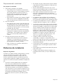
Page. 6
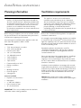
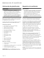
Installation instructions
Planning information
9 CAUTION
To prevent possible damage to cabinets and cabinet
finishes, use only materials and finishes that will not
discolor or divide into layers. Materials should be able
to withstand temperatures up to 194 °F (90 °C). Heat
and moisture resistant adhesive must be used if the
product is to be installed in laminated cabinetry.
Check with the manufacturer to ensure materials meet
these requirements.
Before using your appliance, be sure to read this manual.
Pay special attention to the Important Safety Instructions
located at the beginning of the manual.
Any opening in the wall behind the appliance and in the
floor under the appliance shall be sealed.
Tools needed
• 7/16'' box end wrench or ratchet
• 3/16'' (4.76 mm) drill bit
• Hand or electric drill
• 1/8'' (3.17 mm) drill bit
• 12'' Adjustable wrench
• T-20 screwdriver
• T-30 screwdriver
• Tape measure
• Furniture dolly or air sled
• Phillips screwdriver
• Level
• Marking instrument
• Protective gloves
• Safety glasses
Items not included
• Drywall / concrete anchors
•Rope/twine
• 2 – NPT flare adapters
• Pipe compound / tape
• ¾'' (19 mm) flex line
IMPORTANT: There is a possibility to discolor the back
wall under certain cooking conditions.
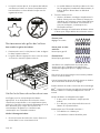
Ventilation requirements
9 WARNING
This appliance should not be installed with a
ventilation system that directs air in a downward
direction toward the range. This type of ventilation
system may cause ignition and combustion problems
with the appliance resulting in personal injury,
property damage, or unintended operation.
Ventilating systems that direct the air upwards do not
have any restriction.
Refer to the “Ventilation Planning Guide” for approved
ventilation combinations.
It is strongly recommended that this appliance be installed
in conjunction with a Thermador
®
vent hood. Due to the
high heat capability of this unit, particular attention should
be paid to the hood and duct work installation to assure it
meets local building codes.
Downdraft ventilation should not be used. The
“Ventilation Planning Guide” indicates the ventilation
hood options and blower capacity guidelines that are
recommended for use.
Due to the high heat of the rangetop burners, installing a
microwave oven with a ventilation system over the
rangetop is not recommended on any model other than
the 30'' 5–burner. Refer to OTR manufacturer’s installation
manual for clearances.
Ventilation hoods and blowers are designed for use with
single wall ducting. However, some local building codes or
inspectors may require double wall ducting. Consult local
building codes and/or local agencies before starting to
assure that hood and duct installation will meet local
requirements.
NOTICE: Most range hoods contain combustible
components which must be considered when planning the
installation.

Page. 7
Ventilation preparation
To prepare for the ventilation
1. Select hood and blower models:
• For wall installations, the hood width must, at a
minimum, equal the width of the range/rangetop.
Where space permits, a hood larger in width than
the range/rangetop may be desirable for
improved ventilation performance.
• For island installations, the hood width should
overhang the width of the range/rangetop by a
minimum of 3'' (76 mm) on each side.
2. Hood placement:
• For best smoke elimination, the lower edge of the
hood should be installed 30'' (762 mm) above the
range cooking surface.
• If the hood contains any combustible materials
(i.e. a wood covering), it must be installed a
minimum of 36'' (914 mm) above the cooking
surface.
3. Consider make-up air:
• Due to the high volume of ventilation air, a source
of outside replacement air is recommended. This
is particularly important for tightly sealed and
insulated homes.
• A qualified heating and ventilating contractor
should be consulted.
Installation clearances
Cabinet requirements
The appliance is a free standing unit. If the unit is to be
placed adjacent to cabinets, the clearances shown in this
section are required. The same clearances apply to island
installations, except for the overhead cabinets, which must
have a space wide enough to accept the island hood.
• See the “Ventilation planning guide” for
recommended hood options. Due to the high heat of
the burners, installing a microwave oven with a
ventilation system over the appliance is not
recommended on any model other than the 30'' 5–
burner. Refer to OTR manufacturer’s installation
manual for clearances.
• The gas and electrical supply should be within the
zones shown in the “Gas and electric locations”
section.
• The shaded area behind the appliance indicates an
opportunity to discolor the back wall under certain
cooking conditions.
• There must be a minimum of 5'' (127 mm) side
clearance from the appliance to combustible vertical
surfaces above the 36'' (914 mm) counter height.
• Within the 5'' (127 mm) side clearance to combustible
vertical surfaces above 36'' (91.4 cm), the maximum
wall cabinet depth must be 13” (330 mm).
• Wall cabinets within this 5'' (127 mm) side clearance
must be 18'' (457 mm) above the 36'' (914 mm) high
countertop.
• The maximum depth of the cabinets hanging on either
side of the hood is 13'' (330 mm).
• There is a 36'' (914 mm) minimum clearance required
between the top of the cooking surface and the
bottom of an unprotected cabinet. A 30'' (762 mm)
clearance can be used when the bottom of the wood
or metal cabinet is protected by not less than 1/4''
(6 mm) of a flame retardant material covered with not
less than No. 28 MSG sheet steel, 0.015'' (0.38 mm)
thick stainless steel, 0.024'' (0.61 mm) aluminum, or
0.02'' (0.51 mm) thick copper.
• DO NOT obstruct the flow of combustion and
ventilation air to the appliance.
• The appliance height is adjustable. The level of the
range top must be at the same level or above the
counter top level.
• To provide proper ventilation of the range DO NOT
remove range feet.
• Any openings in the wall behind the appliance and in
the floor under the appliance must be sealed.
Rear clearance requirements
• To avoid staining on the back wall, high temperature,
non-porous construction materials suitable for use in a
cooking environment are recommended.
• Model PCG305xx, PRG305xx, PRG304xx, PRD305xx,
PRD304, and PRD606xx are suitable for 0'' rear
clearance to combustible surfaces.
• All other models:
• When using the included island trim a minimum 6"
(152 mm)* rear clearance is required to a
combustible surface*.
• When installing against a combustible surface, a
Thermador
®
low backguard is required for a 0''
rear clearance to the combustible surface. A
Thermador low backguard must be purchased
separately.
• A rear clearance to a surface covered in a non-
combustible material (metal, ceramic tile, brick,
marble, or stone)
*
is 0" when using the included
Island Trim.
*Clearances of less than 6'' (152 mm) should be approved by the
local codes and/or by the local authority having jurisdiction.
Clearances from non-combustible materials are not part of the
ANSI Z21.1 scope and are not certified by CSA.

Page. 8
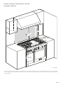
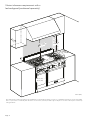
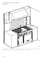
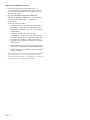
Cabinet clearance requirements with the
included island trim
as defined in the “National Fuel Gas Code” (ANSI Z223.1, Current Edition). Clearances from non-combustible materials are not part of the ANSI
Z21.1 scope and are not certified by CSA. Clearances of less than 6'' (152 mm) should be approved by the local codes and/or by the local authority
having jurisdiction.
5
" (12
7
)
1
8
"
(457)
1
8
"
(
457)
1
8
"
(457)
30" (762) –
36" (914)
30" (762) –
36" (914)
30" (762) –
36" (914)
30", 36", or 48"
(762, 914, or 1219 )
30", 36", or 48"
(762, 914, or 1219 )
30", 36", or 48"
(762, 914, or 1219 )
13"
(330)
13"
(330)
13"
(330)
6" (152)6" (152)6" (152)
35 ⅞" (911) –
36 ¾" (933)
35 ⅞" (911) –
36 ¾" (933)
35 ⅞" (911) –
36 ¾" (933)
inches (mm)

Page. 9
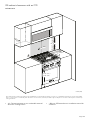
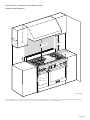
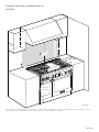
Cabinet clearance requirements with a
low backguard (purchased separately)
as defined in the “National Fuel Gas Code” (ANSI Z223.1, Current Edition). Clearances from non-combustible materials are not part of the ANSI
Z21.1 scope and are not certified by CSA. Clearances of less than 6'' (152 mm) should be approved by the local codes and/or by the local authority
having jurisdiction.
1
8
"
(457)
1
8
"
(
457)
1
8
"
(457)
30", 36", or 48"
(762, 914, or 1,219 )
30", 36", or 48"
(762, 914, or 1,219 )
30", 36", or 48"
(762, 914, or 1,219 )
0"0"
5
" (12
7
)
30" (762) –
36" (914)
30" (762) –
36" (914)
30" (762) –
36" (914)
13"
(330)
13"
(330)
13"
(330)
35 ⅞" (911) –
36 ¾" (933)
35 ⅞" (911) –
36 ¾" (933)
35 ⅞" (911) –
36 ¾" (933)
inches (mm)

Page. 10
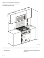
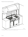
305 cabinet clearances with an OTR
microwave
• 30'' (762 mm) minimum to non-combustible material
above the cooking surface.
• * Refer to OTR manufacturer’s installation manual for
clearances.
as defined in the “National Fuel Gas Code” (ANSI Z223.1, Current Edition). Clearances from non-combustible materials are not part of the ANSI
Z21.1 scope and are not certified by CSA. Clearances of less than 6'' (152 mm) should be approved by the local codes and/or by the local authority
having jurisdiction.
*
30" (762)
*
30" (762)
*
30" (762)
30" (762)30" (762)30" (762)
1
8
"
(457)
1
8
"
(
457)
1
8
"
(457)
0"0"
5
" (12
7
)
13"
(330)
13"
(330)
13"
(330)
35 ⅞" (911) –
36
¾" (933)
35
⅞" (911) –
36
¾" (933)
35
⅞" (911) –
36
¾" (933)
inches (mm)

Page. 11
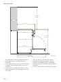
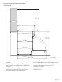
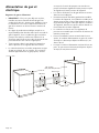
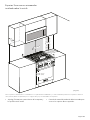
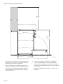
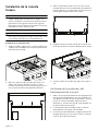
Side clearances
• The model shown is with the included island trim. A
low backguard option is available (purchased
separately).
• For an island trim install, counter surface should have
a cantilever edge meeting the back section of the
island trim.
• If an inner wall is used under the cantilever counter
top there should be a 1/8'' (3 mm) gap from the rear
of the range.
• There is a 44-7/8'' (1,140 mm) total clearance.
• Shaded area behind range indicates minimum
clearance to combustible surfaces. Combustible
materials cannot be located within this area with the
Island Trim.
• There is a 23-7/8'' (606 mm) maximum recess depth.
28" (711)
23
⅞" (606)
23" (584)
44 ⅞" (1,140)
24 ⅝" (625)
24
¾" (629)
30" (762) –
36" (914)
36
¾" (933) –
35
⅞" (911)
6" (152) 6" (152) 6" (152)
inches (mm)

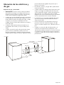
Page. 12
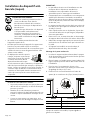
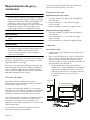
Gas and electric locations
Gas and electrical requirements
• IMPORTANT: If not already present, install gas shut-
off valve in an easily accessible location. Make sure all
users know where and how to shut off the gas supply
to the range.
• A metal flex line or fixed metal pipe shall be used to
connect gas to the appliance. If a metal gas line
cannot be used, consult your local certified electrician
or local electric codes for proper grounding.
• Any opening in the wall behind the appliance and any
opening in the floor under the appliance must be
sealed.
• The range must be connected only to the type of gas
for which it is certified. If the range is to be connected
to propane gas, ensure that the propane gas supply
tank is equipped with its own high pressure regulator
in addition to the pressure regulator supplied with the
range.
• The gas and electrical supplies must be within the
zones as indicated in the image below.
• A manual gas shut-off valve must be installed external
to the appliance, in a location accessible from the
front, for the purpose of shutting off the gas supply.
The supply line must not interfere with the back of the
unit.
• The range is supplied with its own pressure regulator
that has been permanently mounted within the range
body.
• For nearly-flush installation to the back wall, the gas
supply line and electrical cord should not go above 9''
(229 mm) above the floor.
• When the power supply cord or conduit is connected
to the mating receptacle or terminal block cover, the
combined plug/receptacle or terminal block cover/
conduit connector should protrude no more than 2''
(51 mm) from the rear wall.
9"
(229)
9"
(229)
9"
(229)
6"
(152)
6"
(152)
6"
(152)
30", 36", 48"
(762, 914, 1219)
30", 36", 48"
(762, 914, 1219)
30", 36", 48"
(762, 914, 1219)
6"
(152)
6"
(152)
6"
(152)
2"
(51)
2"
(51)
2"
(51)
CC
LL
CC
LL
6"
(152)
6"
(152)
6"
(152)
6"
(152)
6"
(152)
6"
(152)
Electric zoneElectric zoneElectric zone
Gas zoneGas zoneGas zone
inches (mm)

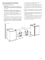
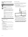
Page. 13
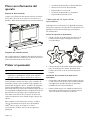
Unpacking and moving the
range
9 CAUTION
DO NOT lift the range by the oven door’s
handle, as this may damage the door hinges
and cause the door to fit incorrectly.
DO NOT lift the appliance by the range’s
control panel.
The unit is heavy and should be handled
accordingly. Proper safety equipment such as
gloves and adequate manpower of at least two
people must be used in moving the range to
avoid injury and to avoid damage to the unit or
the floor.
Rings, watches, and any other loose items that
may damage the unit or otherwise might
become entangled with the unit should be
removed.
Hidden surfaces may have sharp edges. Use
caution when reaching behind or under
appliance.
DO NOT use a hand truck or appliance dolly on
the back or front of the unit. Handle from the
side only.
Unpacking the range
NOTES:
• DO NOT remove control panel foam until unit is
completely installed.
• DO NOT lift on the control panel at any point during
the installation.
To unpack the appliance
1. Remove the outer carton and packing materials from
the shipping pallet.
2. Leave the protective film over brushed-metal surfaces,
to protect finish from scratches, until the range is
installed in its final position.
3. Remove the grates, burner caps and oven racks to
facilitate handling.
4. If desired, the oven doors may be removed (see “Door
removal and adjustment”).
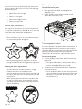
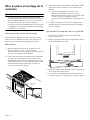
Moving the range
Due to the weight, a furniture dolly with soft wheels or an
air lift should be used to move this unit. The weight must
be supported uniformly across the bottom.
To remove the pallet bolts
1. To remove the pallet bolts in the front and in the back,
use a 7/16'' wrench or ratchet and socket to remove
the pallet bolt from the bottom of the pallet.
2. Lift range and remove it from the pallet. Use
additional help as required to remove from pallet.
3. Transport the range by furniture dolly close to its final
location. Unit should not be dollied from the front. DO
NOT slide the range across an unprotected floor.
4. The range can then be tipped back and supported on
the rear legs while the dolly is carefully removed. THE
FLOOR UNDER THE LEGS SHOULD BE PROTECTED
BEFORE PUSHING THE UNIT INTO POSITION.

Page. 14
Installing the anti-tip bracket
(required)
For all ranges, an anti-tip device must be installed as per
these instructions.
9 WARNING
RANGE TIPPING HAZARD
• All ranges can tip and injury can result. To
prevent accidental tipping of the range,
attach it to the floor by installing the Anti-
Tip Bracket supplied.
• A risk of tip-over may exist if the appliance
is not installed in accordance with these
instructions. For all ranges an anti-tip device
MUST be installed.
• A child or adult can tip the range and be killed.
• DO NOT operate the range without the anti-tip
device in place and engaged. Failure to do so can
result in death or serious burns to children or
adults.
• If the range is pulled away
from the wall for cleaning,
service or for any other
reason, ensure that the Anti-
Tip Device is properly re-
engaged when the range is pushed back against
the wall. In the event of abnormal usage (such as a
person standing, sitting, or leaning on an open
door), failure to take this precaution can result in
tipping of the range. Personal injury might result
from spilled hot liquids or from the range itself.
9 WARNING
ELECTRICAL SHOCK HAZARD
• Use extreme caution when drilling holes into the
wall or floor as there may be concealed electrical
wires.
• Identify the electrical circuits that could be
affected by the installation of the Anti-Tip Bracket,
then turn off power to these circuits.
• Failure to follow these instructions may result in
electrical shock or other personal injury.
IMPORTANT:
• Hardware provided is for mounting through standard
thickness wood studs. Installers are responsible to
provide hardware for other types of mounting
situations.
• Contact a qualified installer or contractor to
determine the proper method for drilling holes
through the wall or floor material (such as ceramic tile,
hardwood, etc.)
• The bracket may be attached to a solid wood surface
having a minimum wall thickness of ¾'' (19 mm).
• The thickness of the wall or floor may require use of
longer screws, available at your local hardware store.
• In all cases, at least two (2) of the bracket mounting
screws must be fastened to solid wood surface.
• Use appropriate anchors when fastening the mounting
bracket to any material other than hardwood or metal.
• If the range is moved to a new location, the Anti-Tip
Device must be removed and reinstalled.
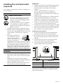
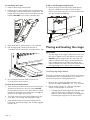
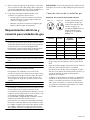
Installing the anti-tip bracket
1. Locate the anti-tip bracket in the literature packet,
inside the box that was on top of the appliance.
2. Place bracket on the floor in a position shown below.
The bracket may be placed on either the left or the
right side.
3. For walls, wall studs, or floors composed of solid
wood or metal, drill 1/8'' (3 mm) pilot holes.
4. Secure to floor and/or wall stud using the (4) 1½''
(38 mm) Phillips head screws provided.
Later, when the unit is installed, the adjustable leg will
slide under the bracket.
Model Value for 'X'
30'' 1-3/4'' (45 mm)
36'' 2-3/16'' (56 mm)
48'' 1-3/4'' (45 mm)
C
L
C
L
xx
xx
C
L

Page. 15
Gas requirements and hookup
9 CAUTION
The appliance must be isolated from the gas supply
piping system by closing its individual manual shut-off
valve during any pressure testing of the gas supply
piping system at test pressures equal to or less than 1/
2 psig (3.5kPa.).
9 WARNING
DO NOT use a flame of any kind to check for gas
leaks.
9 CAUTION
When connecting unit to propane gas, make certain
the propane gas tank is equipped with its own high
pressure regulator in addition to the pressure
regulator supplied with the appliance. The pressure of
the gas supplied to the appliance regulator must not
exceed 14" water column (34.9 mb).
IMPORTANT: Do not ground to a gas pipe.
Verify the type of gas being used at the installation site.
Make certain the range matches the type of gas available
at this location.
The gas supply connections shall be made by a competent
technician and in accordance with local codes or
ordinances. In the absence of local codes, the installation
must conform to the National Fuel Gas Code ANSI
Z223.1/NFPA54- current issue.
High altitude
This appliance has been tested for operation up to an
altitude of 10,100 ft (3,078 m) elevation above sea level.
A high altitude kit is required for natural gas above 5,400
feet (1,646 m) elevation above sea level, and for propane
(LP) above 10,000 feet (3048 m) elevation above sea level.
If desired, for altitudes above 2,000 feet (610 m) elevation
above sea level, adjustments can be made to the
rangetop burners with an adjustment kit. If flame
performance is satisfactory, adjustment will not be
required. It is required that a Certified Professional make
the high altitude adjustments during installation.
See the back cover for information about service, parts,
and accessories.
Gas requirements
Natural gas requirements:
• Inlet connection: 1/2'' NPT internal (Minimum 3/4''
dia. flex line)
• Supply pressure: 7'' min. to 14'' max. water column
(17.4 to 34.9 mb)
• Manifold pressure: 5'' water column (12.5 mb)
Propane gas requirements
• Inlet connection: 1/2'' NPT internal (minimum 3/4''
dia. flex line)
• Supply pressure: 11'' min. to 14'' max. water column
(27.4 mb to 34.9 mb)
• Manifold pressure: 10'' water column (24.9 mb)
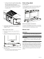
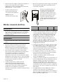
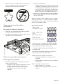
Gas connection
To connect the gas
1. Make sure the gas supply is turned off at the manual
shut-off valve before connecting the appliance.
2. Use a ¾'' (19 mm) flex line to connect between the
gas supply and the appliance gas inlet. The gas supply
line connection is located at the lower right portion.
The appliance gas inlet connection is ½'' (12.7 mm)
NPT.
• Use caution to avoid crimping the ¾'' (19 mm) flex
line when making bends. Suggested length of flex
line is 48" (1219 mm); however, please check local
codes for your area's requirements before
installation.
3. Use pipe sealing compound or Teflon
®
tape on the
pipe threads. DO NOT apply sealing compound or
tape to flare fittings. Take care not to apply excessive
pressure when tightening the fittings.
¾" (19) external threads¾" (19) external threads¾" (19) external threads
½" (12.7) internal threads½" (12.7) internal threads½" (12.7) internal threads
{
¾" (19)
Flex line
¾" (19)
Flex line
¾" (19)
Flex line
inches (mm)

Page. 16
4. Leak testing of the appliance shall be in accordance
with the following instructions:
• Turn on gas and check supply line connections for
leaks using a soap and water solution.
• Bubbles forming indicate a gas leak. Repair all
leaks immediately.
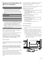
Electrical requirements and
connection for GAS models
9 WARNING
Before installing, turn power OFF at the service panel.
Lock service panel to prevent power from being
turned ON accidentally. Always disconnect appliance
from the electric supply either by disconnecting
power cord or shutting off the breaker at the service
panel before servicing the appliance.
9 WARNING
This product must be properly grounded.
9 WARNING
Electrical grounding instructions
This appliance is equipped with a three-prong
grounding plug for your protection against shock
hazard and should be plugged directly into a properly
grounded receptacle. DO NOT cut or remove the
grounding prong from this plug.
9 CAUTION
Improper grounding or reverse polarization will cause
malfunction (such as continuous sparking of the
burner igniters). This can damage the appliance and
can create a condition of shock hazard. If the
dedicated circuit is not correctly grounded and
polarized, it is the responsibility and obligation of the
installer and user to have the existing receptacle
changed to a properly dedicated grounded and
polarized receptacle. This must be accomplished in
accordance with all applicable local codes and
ordinances by a qualified electrician. In the absence of
local codes and ordinances, the receptacle
replacement shall be in accordance with the National
Electric Code.
INSTALLER — show the owner the location of the circuit
breaker. Mark it for easy reference.
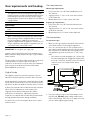
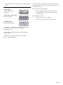
Gas unit electrical connection
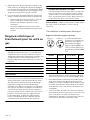
Electrical supply circuit requirements
The cord supplied with the
gas ranges having an electric
griddle or grill requires a
NEMA 5-20 receptacle. All
other gas units require a
NEMA 5-15 receptacle.
• Before you plug in an electrical cord, be sure all
controls are in the OFF position.
• A neutral supply wire must be provided from the
power source (breaker) because critical range
components, including the surface burner spark
reignition modules, require it to operate safely and
properly.
• All 120 volt models must be plugged into a mating 3-
prong, grounding-type receptacle. The receptacle
must be connected to a properly dedicated grounded
and polarized electrical power supply rated at
120VAC, single phase, 60Hz.
• Observe all governing codes and ordinances when
grounding. In the absence of these codes or
ordinances observe National Electrical Code ANSI/
NFPA No. 70 current issue, or the relevant Canadian
Electric Code, CSA C22.1-02.
Model Voltage Dedicated circuit Phase
Pxx305Wx 120 VAC 15 Amps Single
Pxx366Wx 120 VAC 15 Amps Single
Pxx364WDx 120 VAC 20 Amps Single
Pxx364WLx 120 VAC 20 Amps Single
Pxx486WDx 120 VAC 20 Amps Single
Pxx486WLx 120 VAC 20 Amps Single
• Power cord and receptacle
should protrude no more than
2'' (51 mm) from the rear wall.
NOTE: Plug styles may vary.
NEMA 5-15 NEMA 5-20
G
G
N
N
2"
(51)

Page. 17
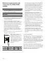
Electrical requirements and
connection for DUAL FUEL
models
9 WARNING
An improper 240/208 VAC power supply will cause
malfunction, damage to this appliance, and possibly
create a condition of shock hazard.
9 WARNING
This product must be properly grounded.
• Before installing, turn power OFF at the service panel.
Lock service panel to prevent power from being
turned ON accidentally.
• Prior to servicing appliance, always disconnect
appliance electrical supply cord, if so equipped, from
wall receptacle. If appliance is hard-wired to power
supply, disconnect power to unit by turning off the
proper circuit breaker. Lock service panel to prevent
power from being turned ON accidentally.
• A neutral supply wire must be provided from the
power source (breaker) because critical range
components, including the surface burner spark re-
ignition module, require it to operate safely and
properly.
• Mount the receptacle securely to a wall stud, then seal
around the receptacle's housing.
• If the correct power supply circuit is not provided, it is
the responsibility and obligation of the installer and
user to have proper power supply connected. This
must be accomplished in accordance with all
applicable local codes and ordinances by a qualified
electrician. It is the responsibility of the installer to
ensure compliance of local codes. In the absence of
local codes and ordinances, the power supply
connection shall be in accordance with the National
Electric Code.
• Observe all governing codes and ordinances when
grounding. In the absence of these codes or
ordinances observe National Electrical Code ANSI/
NFPA No. 70 current issue. See the following
information in this section for grounding method.
• Electrical wiring diagrams and schematics have been
placed in the kick panel area of the range for access
by a qualified service technician.
• The ranges are to be connected to a 240/208 VAC
power supply.
• Dual Fuel models must be connected to the power
supply utilizing one of the following methods. For all
methods of connection, the length of the cord or
conduit/wiring must allow the unit to be slid
completely out of the cabinet without having to
unplug or disconnect the unit from the power supply.
• Recommended minimum free length of cord or
conduit is 4ft (1.2 m). Electrical installations and
grounding must be in accordance with all local codes
and ordinances, and/or the National Electric Code, as
applicable.
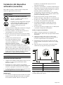
4-wire connection
This appliance must be connected to the power supply
with a listed (UL, CSA, ...) 3-POLE, 4-CONDUCTOR cord
kit rated 125/250 VOLTS, 50 AMPERES DEDICATED
CIRCUIT, and marked for use with ranges. It is the
responsibility of the installer to provide the proper wiring
components (cord, wires, etc.) and complete the electrical
connection as dictated by local codes and ordinances,
and/or the National Electrical Code.
The cord kit is required to be attached to the range
terminal block with a strain relief (not provided) which will
fit a 1'' (25.4 mm) diameter hole. If not already equipped,
the cord must also have 1/4'' (6 mm) faston closed-loop
lugs attached to the free ends of the individual
conductors, preferably soldered in place.
When using a receptacle it may
be necessary to recess the
receptacle's housing into the rear
wall. Refer to Local Electrical
Code to determine the minimum
volume for all electrical / junction
boxes. Follow all local electrical
codes and ordinances, and/or the
National Electric Code, as
applicable.
Volt Circuit Frequency Phase
240/208 VAC 50 Amps 60 Hz. Single
2" (51) max.

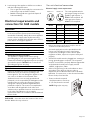
Page. 18
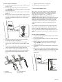
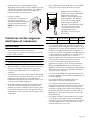
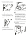
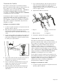
To wire a 4-wire connection
1. Locate the terminal block on the rear of the unit and
remove cover.
2. Remove upper nuts only from the terminal block
studs. DO NOT remove lower nuts which secure range
internal wiring leads.
3. If applicable, remove the 4-wire power cord from the
appliance.
4. Mount strain relief (not provided with range) into the
1'' (25.4 mm) diameter hole in the back panel located
below the terminal block. Route wires up through
strain relief.
5. Remove green ground screw and serrated washer
located beneath the terminal block.
6. Secure the neutral, grounded wire of the supply
circuit, to the center stud of the terminal block with
nut.
7. Secure the L1 (red) and L2 (black) power leads to the
outside terminal studs (brass colored) with nuts.
8. Secure the bare copper ground lead to the range
chassis using the ground screw and serrated washer.
Be sure that neutral and ground terminals do not
touch.
9. Tighten all connections securely and
10. Reinstall the terminal block cover.
3-wire lead connection
Where local codes and ordinances permit grounding
through neutral, and conversion of supply to 4-wire is
impractical, the unit may be connected to the power
supply with a Listed (UL, CSA, ...) 3-POLE, 3-
CONDUCTOR cord kit rated 125/250 VOLTS, 50
AMPERES DEDICATED CIRCUIT, and marked for use with
ranges. It is the responsibility of the installer to provide
the proper wiring components (cord, wires, etc.) and
complete the electrical connection as dictated by local
codes and ordinances, and/or the National Electrical
Code.
The cord kit must be attached to the range back panel
with a strain relief which will fit a 1" (25.4 mm) diameter
hole. If not already equipped, the cord must also have
1/4'' (6 mm) faston closed-loop lugs attached to the free
ends of the individual conductors, preferably soldered in
place.
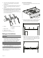
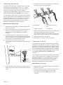
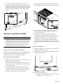
To wire a 3-wire connection
1. Locate the small bag with white jumper wire located in
the literature packet.
2. Locate the terminal block on the rear of the unit and
remove cover.
3. Remove upper nuts only from the terminal block
studs. DO NOT remove nuts which secure range
internal wiring leads.
4. If applicable, remove the 4-wire power cord from the
appliance.
5. Mount strain relief (not provided with range) into the
1'' (25.4 mm) diameter hole in the back panel located
below the terminal block. Route wires up through
strain relief.
a – Red/L1 b – Green/ground
c – White/neutral d – Black/L2
d
c
b
a

Page. 19
6. Secure the neutral, grounded wire of the supply
circuit, to the center stud (silver colored) of the
terminal block.
7. Secure the L1 (red) and L2 (black) power leads to the
outside corresponding terminal block studs (brass
colored).
8. Remove the green ground screw and serrated washer
located beneath the terminal block. Screw one end of
the included white jumper wire to the chassis beneath
the terminal block with the green ground screw.
Secure the other end of the wire to the center stud of
the terminal block with nut.
9. Tighten nuts securely.
10. Reinstall the Terminal Block Cover.
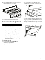
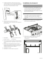
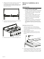
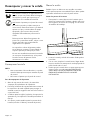
Backguard installation
9 WARNING
Fingers or hands could get pinched when installing
the backguard. Severe injury could result. Use
extreme caution and wear thick protective gloves to
avoid potential laceration to finger or hand while
sliding the backguard down onto the range.
9 WARNING
To reduce the risk of fire or injury to persons, check to
make sure all packaging has been removed from
accessory devices before use.
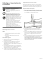
Installation methods will vary upon need. Before you
begin read these instructions carefully. Observe all local
codes and ordinances.
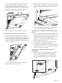
To install the low backguard
1. Remove the T-20 torx screws in the front face of the
included island trim.
2. Remove the T-20 torx screws securing the trim to the
side panels, and the T-20 torx screws securing the
piece to the back panel. Lift up to fully remove.
3. Align the back panel of the new accessory with the
flanges on the range side panel’s right and left rear
corners. The backguard is inserted inside the guide
channels on the back of the range.
a – Red/L1 b – Ground link wire provided
in small bag.
c – White/neutral d – Black/L2
d
c
a
b
Page is loading ...
Page is loading ...
Page is loading ...
Page is loading ...
Page is loading ...
Page is loading ...
Page is loading ...
Page is loading ...
Page is loading ...
Page is loading ...
Page is loading ...
Page is loading ...
Page is loading ...
Page is loading ...
Page is loading ...
Page is loading ...
Page is loading ...
Page is loading ...
Page is loading ...
Page is loading ...
Page is loading ...
Page is loading ...
Page is loading ...
Page is loading ...
Page is loading ...
Page is loading ...
Page is loading ...
Page is loading ...
Page is loading ...
Page is loading ...
Page is loading ...
Page is loading ...
Page is loading ...
Page is loading ...
Page is loading ...
Page is loading ...
Page is loading ...
Page is loading ...
Page is loading ...
Page is loading ...
Page is loading ...
Page is loading ...
Page is loading ...
Page is loading ...
Page is loading ...
Page is loading ...
Page is loading ...
Page is loading ...
Page is loading ...
Page is loading ...
Page is loading ...
Page is loading ...
Page is loading ...
Page is loading ...
Page is loading ...
Page is loading ...
Page is loading ...
Page is loading ...
Page is loading ...
-
 1
1
-
 2
2
-
 3
3
-
 4
4
-
 5
5
-
 6
6
-
 7
7
-
 8
8
-
 9
9
-
 10
10
-
 11
11
-
 12
12
-
 13
13
-
 14
14
-
 15
15
-
 16
16
-
 17
17
-
 18
18
-
 19
19
-
 20
20
-
 21
21
-
 22
22
-
 23
23
-
 24
24
-
 25
25
-
 26
26
-
 27
27
-
 28
28
-
 29
29
-
 30
30
-
 31
31
-
 32
32
-
 33
33
-
 34
34
-
 35
35
-
 36
36
-
 37
37
-
 38
38
-
 39
39
-
 40
40
-
 41
41
-
 42
42
-
 43
43
-
 44
44
-
 45
45
-
 46
46
-
 47
47
-
 48
48
-
 49
49
-
 50
50
-
 51
51
-
 52
52
-
 53
53
-
 54
54
-
 55
55
-
 56
56
-
 57
57
-
 58
58
-
 59
59
-
 60
60
-
 61
61
-
 62
62
-
 63
63
-
 64
64
-
 65
65
-
 66
66
-
 67
67
-
 68
68
-
 69
69
-
 70
70
-
 71
71
-
 72
72
-
 73
73
-
 74
74
-
 75
75
-
 76
76
-
 77
77
-
 78
78
-
 79
79
-
 80
80


Thermador PRD364WDHU Installation guide
- Category
- Cookers
- Type
- Installation guide
Ask a question and I''ll find the answer in the document
Finding information in a document is now easier with AI
in other languages
Related papers
-
Thermador PRD364WLHU Installation guide
-
-
Thermador PRG364WLG Installation guide
-
-
-
Thermador PRI30LBHU Installation guide
-
Thermador PRG364NLH Installation guide
-
-
Thermador PRD486GDHU Installation guide
-
Other documents
-
Bosch HDS8045U Installation guide
-
Hisense HFG3601CPS User manual
-
Bosch HDI8054U/01 Installation guide
-
Maytag Jenn-Air PRD3030 series Installation guide
-
-
Forza FR366GN Installation guide
-
DCS RGV2364GDN Installation guide
-
GE JX36BES Installation guide
-
Jenn-Air JES9900BAS Installation Instructions Manual
-