DeWalt DWS709 Owner's manual

Category
Power tools
Type
Owner's manual
DWS779
12" (305 mm) Double Bevel Sliding Compound Miter Saw
Scie coulissante à onglet mixte 305 mm (12 po)
Sierra ingletadora compuesta deslizante de doble bisel de
305mm (12pulg.)
INSTRUCTION MANUAL
GUIDE D’UTILISATION
MANUAL DE INSTRUCCIONES
INSTRUCTIVO DE OPERACIÓN, CENTROS DE SERVICIO Y PÓLIZA DE
GARANTÍA. ADVERTENCIA: LÉASE ESTE INSTRUCTIVO ANTES DE
USAR EL PRODUCTO.
Questions? Visit us at www.dewalt.com
Des questions ? Rendez nous visite à www.dewalt.com
¿Tiene preguntas? Visítenos en www.dewalt.com
Before returning this product call
1-800-4-
DeWALT
IF YOU SHOULD EXPERIENCE A PROBLEM WITH YOUR D
e
WALT PURCHASE,
CALL 1-800-4-D
e
WALT
IN MOST CASES, A D
e
WALT REPRESENTATIVE CAN RESOLVE
YOUR PROBLEM OVER THE PHONE.
IF YOU HAVE A SUGGESTION OR COMMENT, GIVE US A CALL.
YOUR FEEDBACK IS VITAL TO THE SUCCESS OF D
e
WALT’S
QUALITY IMPROVEMENT PROGRAM.
Final Print Size: 11 x 8.5 inches
English
1
Definitions: Safety Guidelines
The definitions below describe the level of severity for each signal word. Please read the
manual and pay attention to these symbols.
DANGER: Indicates an imminently hazardous situation which, if not avoided, will
result in death or serious injury.
WARNING: Indicates a potentially hazardous situation which, if not avoided, could
result in death or serious injury.
CAUTION: Indicates a potentially hazardous situation which, if not avoided, may
result in minor or moderate injury.
NOTICE: Indicates a practice not related to personal injury which, if not avoided,
may result in property damage.
IF YOU HAVE ANY QUESTIONS OR COMMENTS ABOUT THIS OR ANY D
e
WALT TOOL,
CALL US TOLL FREE AT: 1-800-4-D
e
WALT (1-800-433-9258).
WARNING: To reduce the risk of injury, read the instruction manual.
Important Safety Instructions
WARNING! Read all safety warnings and all instructions. Failure to follow the
warnings and instructions may result in electric shock, fire and/or serious injury.
SAVE ALL WARNINGS AND INSTRUCTIONS
FOR FUTURE REFERENCE
Double Insulation
Double insulated tools are constructed throughout with two separate layers of electrical
insulation or one single layer of reinforced insulation between you and the tool’s electrical
system. Tools built with this insulation system are not intended to be grounded. As a result,
your tool is equipped with a two prong plug which permits you to use extension cords without
concern for maintaining a ground connection.
NOTE: Double insulation does not take the place of normal safety precautions when
operating this tool. The secondary insulation system is for protection against injury resulting
from a possible failure of the primary insulation within the tool.
CAUTION: WHEN SERVICING USE ONLY IDENTICAL REPLACEMENT PARTS. Repair or
replace damaged cords.
Polarized Plugs
Polarized plugs (one blade is wider than the other) are used on equipment to reduce the risk
of electric shock. When provided, this plug will fit in the polarized outlet only one way. If the
plug does not fit fully in the outlet, reverse the plug. If it still does not fit, contact a qualified
electrician to install the proper outlet. Do not change the plug in any way.
Safety Instructions for All Tools
WARNING: To reduce the risk of eye injury, ALWAYS use eye protection when
operating the miter saw.
KEEP GUARD IN PLACE and in working order.
REMOVE ADJUSTING KEYS AND WRENCHES. Form habit of checking to see that
keys and adjusting wrenches are removed from spindle before turning tool on. Tools, scrap
pieces, and other debris can be thrown at high speed, causing injury.
KEEP WORK AREA CLEAN. Cluttered areas and benches invite accidents.
DO NOT USE THE MACHINE IN A DANGEROUS ENVIRONMENT. The use of power
tools in damp or wet locations or in rain can cause shock or electrocution. Keep your work
area well-lit to avoid tripping or placing arms, hands, and fingers in danger.
KEEP CHILDREN AWAY. All visitors should be kept at a safe distance from work area.
Your shop is a potentially dangerous environment.
MAKE WORKSHOP CHILDPROOF with padlocks, master switches, or by removing
starter keys. The unauthorized start-up of a machine by a child or visitor may result in injury.
DON’T FORCE TOOL. It will do the job better and be safer at the rate for which it was
designed.
USE RIGHT TOOL. Don’t force tool or attachment to do a job for which it was not
designed. Using the incorrect tool or attachment may result in personal injury.
WEAR PROPER APPAREL. Do not wear loose clothing, gloves, neckties, rings,
bracelets, or other jewelry which may get caught in moving parts. Nonslip footwear is
recommended. Wear protective hair covering to contain long hair.
ALWAYS USE SAFETY GLASSES. Everyday eyeglasses are NOT safety glasses. Also
use face or dust mask if cutting operation is dusty. ALWAYS WEAR CERTIFIED SAFETY
EQUIPMENT:
ANSI Z87.1 eye protection (CAN/CSA Z94.3).
ANSI S12.6 (S3.19) hearing protection.
NIOSH/OSHA/MSHA respiratory protection.
SECURE THE WORKPIECE. Use clamps or a vise to hold the workpiece on the table
and against the fence or when your hand will be dangerously close to the blade within 6"
(152mm). It is safer than using your hand and it frees both hands to operate tool.
DON’T OVERREACH. Keep proper footing and balance at all times. Loss of balance may
cause personal injury.
MAINTAIN TOOLS WITH CARE. Keep tools sharp and clean for best and safest
performance. Follow instructions for lubricating and changing accessories. Poorly
maintained tools and machines can further damage the tool or machine and/or cause
injury.
TURN THE MACHINE “OFF”, AND DISCONNECT THE MACHINE FROM THE
POWER SOURCE before installing or removing accessories, before adjusting or changing
set-ups, when making repairs or changing locations. An accidental start-up can cause
injury. Do not touch the plug’s metal prongs when unplugging or plugging in the cord.
REDUCE THE RISK OF UNINTENTIONAL STARTING. Make sure that the switch is in
the “OFF” position before plugging in the power cord.
USE PROPER EXTENSION CORD. Make sure your extension cord is in good condition.
When using an extension cord, be sure to use one heavy enough to carry the current your
product will draw. An undersized cord will cause a drop in line voltage resulting in loss of
power and overheating. The following table shows the correct size to use depending on
cord length and nameplate ampere rating. If in doubt, use the next heavier gauge. The
smaller the gauge number, the heavier the cord.
Minimum Gauge for Cord Sets
Ampere Rating
Volts Total Length of Cord in Feet (meters)
120V 25 (7.6) 50 (15.2) 100 (30.5) 150 (45.7)
240V 50 (15.2) 100 (30.5) 200 (61.0) 300 (91.4)
More
Than
Not More
Than
AWG
0 6 18 16 16 14
6 10 18 16 14 12
10 12 16 16 14 12
12 16 14 12 Not Recommended
English
2
NEVER CUT FERROUS METALS (those with any iron or steel content) or masonry.
Either of these can cause the carbide tips to fly off the blade at high speeds causing serious
injury.
DO NOT USE ABRASIVE WHEELS. The excessive heat and abrasive particles generated
by them may damage the saw and cause personal injury.
NEVER HAVE ANY PART OF YOUR BODY IN LINE WITH THE PATH OF THE SAW
BLADE. Personal injury will occur.
NEVER APPLY BLADE LUBRICANT TO A RUNNING BLADE. Applying lubricant could
cause your hand to move into the blade resulting in serious injury.
DO NOT place either hand in the blade area when the saw is connected to the power
source. Inadvertent blade activation may result in serious injury.
DO NOT PERFORM FREEHAND OPERATIONS (workpiece not supported by table and
fence). Hold the work firmly against the fence and table. Freehand operations on a miter
saw could cause the workpiece to be thrown at high speeds, causing serious injury.
NEVER REACH AROUND OR BEHIND THE SAW BLADE. A blade can cause serious
injury.
DO NOT REACH UNDERNEATH THE SAW unless it is unplugged and turned off.
Contact with saw blade may cause personal injury.
SECURE THE MACHINE TO A STABLE SUPPORTING SURFACE. Vibration can
possibly cause the machine to slide, walk, or tip over, causing serious injury.
USE ONLY CROSSCUT SAW BLADES recommended for miter saws. For best results,
do not use carbide tipped blades with hook angles in excess of 7 degrees. Do not use
blades with deep gullets. These can deflect and contact the guard, and can cause damage
to the machine and/or serious injury.
USE ONLY BLADES OF THE CORRECT SIZE AND TYPE specified for this tool to
prevent damage to the machine and/or serious injury.
INSPECT BLADE FOR CRACKS or other damage prior to operation. A cracked or
damaged blade can come apart and pieces can be thrown at high speeds, causing serious
injury. Replace cracked or damaged blades immediately.
CLEAN THE BLADE AND BLADE CLAMPS prior to operation. Cleaning the blade
and blade clamps allows you to check for any damage to the blade or blade clamps. A
cracked or damaged blade or blade clamp can come apart and pieces can be thrown at
high speeds, causing serious injury.
DO NOT use lubricants or cleaners (particularly spray or aerosol) in the vicinity of the
plastic guard. The polycarbonate material used in the guard is subject to attack by certain
chemicals.
ALWAYS USE THE KERF PLATE AND REPLACE THIS PLATE WHEN DAMAGED.
Small chip accumulation under the saw may interfere with the saw blade or may cause
instability of workpiece when cutting.
USE ONLY BLADE CLAMPS SPECIFIED FOR THIS TOOL to prevent damage to the
machine and/or serious injury.
CLEAN THE MOTOR AIR SLOTS of chips and sawdust. Clogged motor air slots can
cause the machine to overheat, damaging the machine and possibly causing a short which
could cause serious injury.
KEEP ARMS, HANDS, AND FINGERS AWAY FROM THE BLADE to prevent severe
cuts. Clamp all workpieces that would cause your hand to be within 6"(152mm) of the
saw blade.
NEVER LOCK THE SWITCH IN THE “ON” POSITION. Severe personal injury may
result.
TURN OFF THE MACHINE and allow the blade to come to a complete stop before
raising the arm and prior to cleaning the blade area, removing debris in the path of the
blade, before servicing or adjusting tool. A moving blade can cause serious injury.
CHECK FOR DAMAGED PARTS. Before further use of the tool, a guard or other part
that is damaged should be carefully checked to determine that it will operate properly and
perform its intended function—check for alignment of moving parts, binding of moving
parts, breakage of parts, mounting and any other conditions that may affect its operation.
A guard or other part that is damaged should be properly repaired or replaced. Do not use
tool if switch does not turn it on and off.
USE RECOMMENDED ACCESSORIES. Use only accessories that are recommended
by the manufacturer for your model. Accessories that may be suitable for one tool may be
hazardous when used on another tool. Consult the instruction manual for recommended
accessories. The use of improper accessories may cause risk of injury to persons.
NEVER STAND ON TOOL. Serious injury could occur if the tool is tipped or if the cutting
tool is unintentionally contacted.
NEVER LEAVE TOOL RUNNING UNATTENDED. TURN POWER OFF. Don’t leave
tool until it comes to a complete stop. Serious injury can result.
DO NOT OPERATE ELECTRIC TOOLS NEAR FLAMMABLE LIQUIDS OR IN
GASEOUS OR EXPLOSIVE ATMOSPHERES. Motors in these tools may spark and
ignite fumes.
STAY ALERT, WATCH WHAT YOU ARE DOING, AND USE COMMON SENSE. DO
NOT USE THE MACHINE WHEN YOU ARE TIRED OR UNDER THE INFLUENCE
OF DRUGS OR ALCOHOL. A moment of inattention while operating power tools may
result in injury.
Additional Safety Rules For Miter Saws
WARNING: Do not allow familiarity (gained from frequent use of your saw) to replace safety
rules. Always remember that a careless fraction of a second is sufficient to inflict severe injury.
DO NOT OPERATE THIS MACHINE until it is completely assembled and installed
according to the instructions. A machine incorrectly assembled can cause serious injury.
OBTAIN ADVICE from your supervisor, instructor, or another qualified person if you are
not thoroughly familiar with the operation of this machine. Knowledge is safety.
STABILITY. Make sure the miter saw is placed on a secure supporting surface and does
not slip or move during use.
FOLLOW ALL WIRING CODES and recommended electrical connections to prevent
shock or electrocution. Protect electric supply line with at least a 15 ampere time-delay
fuse or a circuit breaker.
MAKE CERTAIN the blade rotates in the correct direction. The teeth on the blade should
point in the direction of rotation as marked on the saw.
TIGHTEN ALL CLAMP HANDLES, knobs and levers prior to operation. Loose clamps
can cause parts or the workpiece to be thrown at high speeds.
BE SURE all blade and blade clamps are clean, recessed sides of blade clamps are
against blade and arbor screw is tightened securely. Loose or improper blade clamping
may result in damage to the saw and possible personal injury.
ALWAYS USE A SHARP BLADE. Check the blade to see if it runs true and is free from
vibration. A dull or a vibrating blade can cause damage to the machine and/or serious
injury.
DO NOT OPERATE ON ANYTHING OTHER THAN THE DESIGNATED VOLTAGE for
the saw. Overheating, damage to the tool and personal injury may occur.
DO NOT WEDGE ANYTHING AGAINST THE FAN to hold the motor shaft. Damage to
tool and possible personal injury may occur.
DO NOT FORCE CUTTING ACTION. Stalling or partial stalling of motor can cause
damage to the machine or blade and/or serious injury.
ALLOW THE MOTOR TO COME TO FULL SPEED prior to starting cut. Starting the cut
too soon may cause damage to the machine or blade and/or serious injury.
English
3
ON GUARD:
DANGER–KEEP AWAY FROM BLADE.
ON UPPER GUARD:
PROPERLY SECURE BRACKET WITH BOTH SCREWS BEFORE
USE.
ON TABLE: (2 PLACES)
WARNING: FOR YOUR OWN SAFETY, READ INSTRUCTION
MANUAL BEFORE OPERATING MITER SAW. KEEP HANDS
OUT OF PATH OF SAW BLADE. DO NOT OPERATE SAW
WITHOUT GUARDS IN PLACE. CHECK LOWER GUARD FOR
PROPER CLOSING BEFORE EACH USE. ALWAYS TIGHTEN
ADJUSTMENT KNOBS BEFORE USE. DO NOT PERFORM ANY
OPERATION FREEHAND. NEVER REACH IN BACK OF SAW BLADE. NEVER
CROSS ARMS IN FRONT OF BLADE. TURN OFF TOOL AND WAIT FOR SAW
BLADE TO STOP BEFORE MOVING WORKPIECE, CHANGING SETTINGS OR
MOVING HANDS. DISCONNECT POWER BEFORE CHANGING BLADE OR
SERVICING. TO REDUCE THE RISK OF INJURY, RETURN CARRIAGE TO THE
FULL REAR POSITION AFTER EACH CROSSCUT OPERATION. THINK! YOU CAN
PREVENT ACCIDENTS.
ON BASE: (2 PLACES)
Electrical Connection
Be sure your power supply agrees with the nameplate marking. 120 volts, AC means that your
saw will operate on alternating current. The switch is susceptible to failure if direct current is
used. A voltage decrease of 10 percent or more will cause a loss of power and overheating.
All D
e
WALT tools are factory tested. If this tool does not operate, check the power supply.
Accessories
WARNING: Since accessories, other than those offered by D
e
WALT, have not been tested
with this product, use of such accessories with this tool could be hazardous. To reduce the
risk of injury, only D
e
WALT recommended accessories should be used with this product.
Recommended accessories for use with your tool are available for purchase from your local
dealer or authorized service center. If you need assistance in locating any accessory for your
tool, please contact D
e
WALT Industrial Tool Co., 701 East Joppa Road, Baltimore, MD 21286,
call 1-800-4-D
e
WALT (1-800-433-9258) or visit our website: www.dewalt.com.
Optional Accessories (Fig. 1)
The following accessories, designed for your saw, may be helpful. In some cases, other locally
obtained work supports, length stops, clamps, etc., may be more appropriate. Use care in
selecting and using accessories.
Extension Work Support: DW7080
Used to support long overhanging workpieces, the work support is user assembled. Your
saw base is designed to accept two work supports, one on each side.
Adjustable Length Stop: DW7051
Requires the use of one Extension Work Support (DW7080) (refer to Figure 1). It is used
to make repetitive cuts of the same length from 0 to 42" (107cm).
Clamp: DW7082 (similar model included)
Used for firmly clamping workpiece to the saw table for precision cutting.
PROPERLY SUPPORT LONG OR WIDE WORKPIECES. Loss of control of the
workpiece can cause injury.
NEVER CROSS ARMS IN FRONT OF BLADE while using tool. Always make a dry run
(unpowered) before making a finish cut so that you can check the path of the blade or
severe personal injury may result.
ADDITIONAL INFORMATION regarding the safe and proper operation of power tools
(i.e., a safety video) is available from the Power Tool Institute, 1300 Sumner Avenue,
Cleveland, OH 44115-2851 (www.powertoolinstitute.com). Information is also available
from the National Safety Council, 1121 Spring Lake Drive, Itasca, IL 60143-3201. Please
refer to the American National Standards Institute ANSI 01.1 Safety Requirements for
Woodworking Machines and the U.S. Department of Labor OSHA 1910.213 Regulations.
WARNING: Do not connect unit to electrical power source until complete instructions are
read and understood.
WARNING: Always wear proper personal hearing protection that conforms to ANSI
S12.6 (S3.19) during use. Under some conditions and duration of use, noise from this
product may contribute to hearing loss.
WARNING: NEVER MAKE ANY CUT UNLESS THE MATERIAL IS SECURED ON THE
TABLE AND AGAINST THE FENCE.
WARNING: Some dust created by power sanding, sawing, grinding, drilling, and other
construction activities contains chemicals known to the State of California to cause cancer,
birth defects or other reproductive harm. Some examples of these chemicals are:
lead from lead-based paints,
crystalline silica from bricks and cement and other masonry products, and
arsenic and chromium from chemically-treated lumber.
Your risk from these exposures varies, depending on how often you do this type of work.
To reduce your exposure to these chemicals: work in a well ventilated area, and work with
approved safety equipment, such as those dust masks that are specially designed to filter out
microscopic particles.
Avoid prolonged contact with dust from power sanding, sawing, grinding, drilling,
and other construction activities. Wear protective clothing and wash exposed
areas with soap and water. Allowing dust to get into your mouth, eyes, or lay on
the skin may promote absorption of harmful chemicals.
WARNING: Use of this tool can generate and/or disperse dust, which may cause serious
and permanent respiratory or other injury. Always use NIOSH/OSHA approved respiratory
protection appropriate for the dust exposure. Direct particles away from face and body.
For your convenience and safety, the following warning labels are on your miter saw.
ON MOTOR HOUSING:
WARNING: FOR YOUR OWN SAFETY, READ INSTRUCTION MANUAL BEFORE
OPERATING MITER SAW.
WHEN SERVICING, USE ONLY IDENTICAL RE PLACE MENT PARTS.
DO NOT EXPOSE TO RAIN OR USE IN DAMP LOCATIONS.
ALWAYS USE PROPER EYE AND RESPIRATORY PROTECTION.
ON MOVING FENCES:
ALWAYS ADJUST FENCE
PROPERLY BEFORE USE. CLAMP
SMALL PIECES BEFORE CUTTING.
SEE MANUAL.
English
4
Dust Bag: DW7053
Equipped with a zipper for easy emptying, the dust bag will capture the majority of the
sawdust produced.
Crown Molding Fence: DW7084
Used for precision cutting of crown molding.
SAW BLADES: ALWAYS USE 12" (305 mm) SAW BLADES WITH EITHER 1" (25.4 mm) OR
5/8" (15.88 mm) ARBOR HOLES. SPEED RATING MUST BE AT LEAST 4800 RPM. Never
use a smaller diameter blade. It will not be guarded properly. Use crosscut blades only!
Do not use blades designed for ripping, combination blades or blades with hook angles in
excess of 7°.
DW7080
LOCKNUTS
END PLATE
FIG. 1
DW7082
DW7051
BRACKET
KNOBS
DW7084
BLADE DESCRIPTIONS
APPLICATION DIAMETER TEETH
Construction Saw Blades (thin kerf with anti-stick rim)
General Purpose 12" (305 mm) 40
Fine Crosscuts 12" (305 mm) 60
Woodworking Saw Blades (provide smooth, clean cuts)
Fine crosscuts 12" (305 mm) 80
Non-ferrous metals 12" (305 mm) 96
NOTE: For cutting non-ferrous metals, use only saw blades with
TCG (Triple Chip Grind) teeth designed for this purpose.
Unpacking Your Saw
Check the contents of your miter saw carton to make sure that you have received all parts.
In addition to this instruction manual, the carton should contain:
1 DWS779 miter saw
1 D
e
WALT 12" (305 mm) diameter saw blade
In bag:
1 Blade wrench
1 DW7053 dustbag
1 Material clamp
Specifications
CAPACITY OF CUT
50º miter left, 60º miter right,
49º bevel left and right
ANGLE MAXIMUM CAPACITY OF CUT RESULT
0° miter
Height 4.4" (112 mm) Width 9.1" (231 mm)
Width 13.75" (349 mm) Height 3.0" (76 mm)
45° miter
Height 4.4" (112 mm) Width 5.8" (147 mm)
Width 9.6" (244 mm) Height 3.0" (76 mm)
45º bevel – left
Height 3.1" (79 mm) Width 11.4" (290 mm)
Width 13.75" (349 mm) Height 1.7" (43 mm)
45º bevel – right
Height 2.2" (56 mm) Width 11.4" (290 mm)
Width 13.75" (349 mm) Height 1.1" (28 mm)
Your saw is capable of cutting baseboard moldings held vertically 0.8" (20 mm) thick by 6.75"
(171 mm) tall on a 45º right or left miter, when using the slide lock lever (Fig. 7).
NOTE: Your saw is capable of cutting the following once a special setup procedure is
followed. Refer to Special Cuts.
0° miter Height 1.5" (38 mm) Width 16.1" (409mm)
45º miter Height 1.5" (38 mm) Width 11.7" (297mm)
DW7053
English
5
DRIVE
120 V motor
1600 watts in 15 amp motor
3800 RPM Cut helical gears
Multi-V belt Roller bearings
Automatic electric brake Carbide blade
Familiarization
Your miter saw is fully assembled in the car ton.
FIG. 2
Open the box and lift the saw out by the
con venient lifting handle, as shown in
Figure2.
Place the saw on a smooth, flat surface such
as a workbench or strong table.
Examine Figure 4 to become familiar with
the saw and its various parts. The section on
adjus tments will refer to these terms and you
must know what and where the parts are.
CAUTION: Pinch hazard. To reduce the
risk of injury, keep thumb underneath the
operating handle when pulling the handle
down. The lower guard will move up as the operating handle is pulled down, which could
cause pinching. The operating handle is placed close to the guard for special cuts.
Press down lightly on the operating handle and pull out the lock down pin. Gently release the
downward pressure and hold the operating handle, allowing it to rise to its full height. Use the
lock down pin when carrying the saw from one place to another. Always use the lifting handle
to transport the saw, or use the hand indentations shown in Figure 4.
Bench Mounting
Holes are provided in all 4 feet to facilitate bench mounting, as shown in Figure 4. (Two
different-sized holes are provided to accommodate different sizes of screws. Use either hole,
it is not necessary to use both.) Always mount your saw firmly to a stable surface to prevent
movement. To enhance the tool’s portability, it can be mounted to a piece of 1/2" (12.7 mm)
or thicker plywood which can then be clamped to your work support or moved to other job
sites and reclamped.
NOTE: If you elect to mount your saw to a piece of plywood, make sure that the mounting
screws don’t protrude from the bottom of the wood. The plywood must sit flush on the work
support. When clamping the saw to any work surface, clamp only on the clamping bosses
where the mounting screw holes are located. Clamping at any other point will interfere with
the proper operation of the saw.
CAUTION: To prevent binding and inaccuracy, be sure the mounting surface is not warped
or otherwise uneven. If the saw rocks on the surface, place a thin piece of material under one
saw foot until the saw sits firmly on the mounting surface.
IMPORTANT SAFETY INSTRUCTIONS
Changing or Installing a New Saw Blade (Fig. 3)
WARNING: To reduce the risk of injury, turn unit off and disconnect it from
power source before installing and removing accessories, before adjusting or when
making repairs. An accidental start-up can cause injury.
CAUTION:
Never depress the spindle lock button while the blade is under power or coasting.
Do not cut ferrous metal (containing iron or steel) or masonry or fiber cement product
with this miter saw.
Removing the Blade (Fig. 3)
1. Unplug the saw.
2. Raise the arm to the upper position and raise the lower guard (A) as far as possible.
3. Loosen, but do not remove guard bracket screw (B) until the bracket can be raised far
enough to access the blade screw (E). Lower guard will remain raised due to the position
of the guard bracket screw.
4. Depress the spindle lock button (C) while carefully rotating the saw blade by hand until the
lock engages.
5. Keeping the button depressed, use the other hand and the wrench provided (D) to loosen
the blade screw. (Turn clockwise, left-hand threads.)
6. Remove the blade screw (E), outer clamp washer (F), blade (G) and blade adapter (H), if
used. The inner clamp washer (I) may be left on the spindle.
NOTE: For blades with a blade hole of 5/8" (15.88 mm), the 1" (25.4 mm) blade adapter(H)
is not used.
Installing a Blade (Fig. 3)
1. Unplug the saw.
2. With the arm raised, the lower guard held open and the guard bracket raised, place
the blade on the spindle, onto the blade adapter (if using a blade with a 1" [25.4 mm]
diameter blade hole) and against the inner blade clamp with the teeth at the bottom of
the blade pointing toward the back of the saw.
3. Assemble the outer clamp washer onto the spindle.
4. Install the blade screw and, engaging the spindle lock, tighten the screw firmly with
wrench provided (turn counterclockwise, left-hand threads).
NOTE: When using blades with a 5/8" (15.88 mm) diameter blade hole, the blade adapter will
not be used and should be stored in a safe place for future use. The separate blade adapter
is not available on all models.
5. Return the guard bracket to its original position and firmly tighten the guard bracket screw
to hold bracket in place.
WARNING:
The guard bracket must be returned to its original position and the guard
bracket screw tightened before activating the saw.
Failure to do so may allow the guard to contact the spinning saw blade
resulting in damage to the saw and severe personal injury.
Transporting the Saw
WARNING: To reduce the risk of injury, turn unit off and disconnect it from power
source before installing and removing accessories, before adjusting or when making
repairs. An accidental start-up can cause injury.
WARNING: To reduce the risk of serious personal injury, ALWAYS lock the rail lock
knob, miter lock handle, bevel lock handle, lock down pin and fence adjustment knobs before
transporting saw.
In order to conveniently carry the miter saw from place to place, a lifting handle has been
included on the top of the saw arm and hand indentations in the base, as shown in Figure 4.
FEATURES AND CONTROLS
WARNING: To reduce the risk of injury, turn unit off and disconnect it from power
source before installing and removing accessories, before adjusting or when making
repairs. An accidental start-up can cause injury.
English
6
22.5° BEVEL PAWLS (FIG. 6)
Your saw is equipped to rapidly and accurately set a 22.5°
bevel, left or right. The 22.5° bevel pawl can be rotated to
contact the crown adjustment screw.
RAIL LOCK KNOB (FIG. 4)
The rail lock knob allows you to lock the saw head firmly
to keep it from sliding on the rails. This is necessary when
making certain cuts or when transporting the saw.
DEPTH STOP (FIG. 4)
The depth stop allows the depth of cut of the blade to be
limited. The stop is useful for applications such as grooving
and tall vertical cuts. Rotate the depth stop forward and
adjust the depth adjustment screw to set the desired depth
of cut. To secure the adjustment, tighten the wing nut.
Rotating the depth stop to the rear of the saw will bypass
the depth stop feature. If the depth adjustment screw is too
tight to loosen by hand, the provided blade wrench can be
used to loosen the screw.
LOCK DOWN PIN (FIG. 4)
WARNING: The lock down pin should be used ONLY
when carrying or storing the saw. NEVER use the lock down
pin for any cutting operation.
To lock the saw head in the down position, push the saw
head down, push the lock down pin in and release the saw
head. This will hold the saw head safely down for moving
the saw from place to place. To release, press the saw head
down and pull the pin out.
SLIDE LOCK LEVER (FIG. 7)
The slide lock lever places the saw in a position to maximize
cutting of base molding when cut vertically as shown in
Figure 16.
AUTOMATIC ELECTRIC BRAKE
Your saw is equipped with an automatic electric blade
brake which stops the saw blade within 5 seconds of trigger
release. This is not adjustable.
On occasion, there may be a delay after trigger release to
brake engagement. On rare occasions, the brake may not
engage at all and the blade will coast to a stop.
If a delay or “skipping” occurs, turn the saw on and off 4 or 5
times. If the condition persists, have the tool serviced by an
authorized D
e
WALT service center.
Always be sure the blade has stopped before removing it
from the kerf. The brake is not a substitute for guards or for
ensuring your own safety by giving the saw your complete
attention.
OPERATION
WARNING: To reduce the risk of injury, turn unit off
and disconnect it from power source before installing
and removing accessories, before adjusting or when
making repairs. An accidental start-up can cause injury.
MITER CONTROL (FIG. 5)
The miter lock handle and miter latch button allow you to
miter your saw to 60° right and 50° left. To miter the saw,
lift the miter lock handle, push the miter latch button and set
the miter angle desired on the miter scale. Push down on the
miter lock handle to lock the miter angle.
TRIGGER SWITCH (FIG. 4)
The trigger switch turns your saw on and off. A hole is
provided in the trigger for insertion of a padlock to secure
the saw.
MITER LATCH OVERRIDE (FIG. 5)
The miter latch override allows your saw to override the
common stop angles. To override the common stop angles,
push the miter latch button and flip the miter latch override
lever to the vertical position.
BEVEL LOCK KNOB (FIG. 4)
The bevel lock allows you to bevel the saw 49° left or right.
To adjust the bevel setting, turn the knob counterclockwise.
The saw head bevels easily to the left or to the right once the
0° bevel override knob is pulled. To tighten, turn the bevel
lock knob clockwise.
0° BEVEL STOP OVERRIDE (FIG. 4)
The bevel stop override allows you to bevel the saw to the
right past the 0° mark.
When engaged, the saw will automatically stop at 0° when
brought up from the left. To temporarily move past 0° to the
right, pull the bevel lock knob. Once the knob is released,
the override will be reengaged. The bevel lock knob can be
locked out by twisting the knob 180°.
When at 0°, the override locks in place. To operate the
override, bevel the saw slightly to the left.
45° BEVEL STOP OVERRIDE (FIG. 6)
There are two bevel stop override levers, one on each side of
the saw. To bevel the saw, left or right, past 45°, push the 45°
bevel override lever rearward. When in the rearward position,
the saw can bevel past these stops. When the 45° stops are
needed, pull the 45° bevel override lever forward.
CROWN BEVEL PAWLS (FIG. 6)
When cutting crown molding laying flat, your saw is equipped
to accurately and rapidly set a crown stop, left or right (refer
to Instructions for Cutting Crown Molding Laying Flat
and Using the Compound Features). The crown bevel
pawl can be rotated to contact the crown adjustment screw.
The saw is factory set to be used for typical crown in North
America (52/38), but can be reversed to cut non-typical
(45/45) crown. To reverse the crown bevel pawl, remove
the retaining screw, the 22.5° bevel pawl and the 33.9°
crown bevel pawl. Flip the crown bevel pawl so the 30° text
is facing up. Reattach the screw to secure the 22.5° bevel
pawl and the crown bevel pawl. The accuracy setting will
not be affected.
C
FIG. 3
A
B
E
D
H
G
F
E
I
English
7
FIG. 4
KERF
PLATE
MOTOR
HOUSING
RAIL SET
SCREW
ADJUSTMENT
RAIL LOCK
KNOB
MOTOR
ENDCAP
BEVEL SCALE
LOCK DOWN
PIN
MITER
LATCH
BUTTON
TABLE
MITER LATCH
OVERRIDE
MITER
SCALE
MITER LOCK
HANDLE
FENCE
ADJUSTMENT
KNOB
(ONE EACH SIDE)
BENCH MOUNTING HOLES
LIFTING
HANDLE
DUST DUCT
INLET
FENCE
HAND
INDENTATION
RAILS
OPERATING
HANDLE
LOWER
GUARD
BELT COVER
BEVEL LOCK
KNOB
TRIGGER
SWITCH
0° BEVEL
STOP
WING NUT
DEPTH
ADJUSTMENT
SCREW
DEPTH STOP
FENCE
ADJUSTMENT
KNOB
(one each side)
BLADE WRENCH
BASE
FIG. 5
MITER
POINTER
MITER
SCALE
SCREW
(4 places)
MITER POINTER SCREW
MITER
LATCH
BUTTON
MITER LOCK
HANDLE
MITER LATCH
OVERRIDE
English
8
WARNING: Always use eye protection. All users and bystanders must wear eye protection
that conforms to ANSI Z87.1 (CAN/CSA Z94.3).
Plug the saw into any household 60 Hz power source. Refer to the nameplate for voltage. Be
sure the cord will not interfere with your work.
Trigger Switch (Fig. 4)
To turn the saw on, depress the trigger switch. To turn the tool off, release the switch. Allow
the blade to spin up to full operating speed before making the cut. Release the trigger switch
and allow the brake to stop the blade before raising the saw head. There is no provision for
locking the switch on, but a hole is provided in the trigger for insertion of a padlock to lock
the saw off.
Cutting With Your Saw
If the slide feature is not used, ensure the saw head is pushed back as far as possible and
the rail lock knob is tightened. This will prevent the saw from sliding along its rails as the
workpi ece is engaged.
NOTE: Although this saw will cut wood and many non-ferrous materials, we will limit our
detailed discussion to the cutting of wood only. The same guidelines apply to the other
materials. DO NOT CUT FERROUS (IRON AND STEEL) MAT ERIALS OR MASONRY
WITH THIS SAW. Do not use any abrasive blades.
NOTE: Refer to Guard Actuation and Visibility in the Adjustments section for important
information about the lower guard before cutting.
CROSSCUTS
A crosscut is made by cutting wood across the grain at any angle. A straight crosscut is made
with the miter arm at the zero degree position. Set and lock the miter arm at zero, hold the
wood firmly on the table and against the fence. With the rail lock knob tightened, turn on the
saw by squeezing the trigger switch shown in Figure 4.
When the saw comes up to speed (about 1 second) lower the arm smoothly and slowly to cut
through the wood. Let the blade come to a full stop before raising arm.
When cutting anything larger than a 2 x 8 (51 x 203mm [2 x 6 (51 x 152) at 45º miter]) use an
out-down-back motion with the rail lock knob loosened. Pull the saw out, toward you, lower
the saw head down toward the workpiece, and slowly push the saw back to complete the
cut. Do not allow the saw to contact the top of the workpiece while pulling out. The saw may
run toward you, possibly causing personal injury or damage to the workpiece.
Cutting of multiple pieces is not recommended but can be done safely by ensuring that each
piece is held firmly against the table and fence.
NOTE: To provide greater crosscut capacity with reduced stroke, the blade on the DWS779
extends deeper into the table. As a result, a greater lifting force on the workpiece may be
experienced during the cut.
WARNING: Always use a work clamp to maintain control and reduce the risk of workpiece
damage and personal injury, if your hands are required to be within 6" (152 mm) of the blade
during the cut.
NOTE: The rail lock knob shown in Figure 4 must be loose to allow the saw to slide along
its rails.
Miter crosscuts are made with the miter arm at some angle other than zero. This angle is often
45º for making corners, but can be set anywhere from zero to 50º left or 60° right. Make the
cut as described above.
When performing a miter cut on workpieces wider than a 2 x 6 that are shorter in length,
always place the longer side against the fence (Fig. 8).
To cut through an existing pencil line on a piece of wood, match the angle as close as
possible. Cut the wood a little too long and measure from the pencil line to the cut edge to
determine which direction to adjust the miter angle and recut. This will take some practice,
but it is a commonly used technique.
FIG. 6
22.5º BEVEL PAWL
(one each side)
BEVEL POINTER
(one each side)
0° BEVEL ADJUSTMENT
SCREW
BEVEL POINTER SCREW
(one each side)
BEVEL SCALE
CROWN ADJUSTMENT SCREW
(one each side)
45° BEVEL OVERRIDE LEVER
(one each side)
CROWN BEVEL
PAWL
(one each side)
45° BEVEL
ADJUSTMENT SCREW
(one each side)
FIG. 8
FIG. 7
English
9
BEVEL CUTS
A bevel cut is a crosscut made with the saw blade leaning
at an angle to the wood. In order to set the bevel, loosen the
bevel lock (Fig. 4), and move the saw to the left or right as
desired. (It is necessary to move the fence to allow clearance.)
Once the desired bevel angle has been set, tighten the bevel
lock firmly. Refer to the Features and Controls section for
detailed instructions on the bevel system.
Bevel angles can be set from 49º right to 49º left and can be
cut with the miter arm set between 50º left or 60º right. At
some extreme angles, the right or left side fence might have
to be removed. To remove the left or right fence, unscrew the
fence adjustment knob several turns and slide the fence out.
NOTE: Refer to Fence Adjustment in the Adjustments
section for important information on adjusting the fences for
certain bevel cuts.
QUALITY OF CUT
The smoothness of any cut depends on a number of
variables. Things like material being cut, blade type, blade
sharpness and rate of cut all contribute to the quality of the
cut.
When smoothest cuts are desired for molding and other
precision work, a sharp (60 tooth carbide) blade and a
slower, even cutting rate will produce the desired results.
Ensure that the material does not move or creep while
cutting; clamp it securely in place. Always let the blade come
to a full stop before raising arm.
If small fibers of wood still split out at the rear of the
workpiece, stick a piece of masking tape on the wood where
the cut will be made. Saw through the tape and carefully
remove tape when finished.
For varied cutting applications, refer to the list of recommended
saw blades for your saw and select the one that best fits your
needs. Refer to Saw Blades under Optional Accessories.
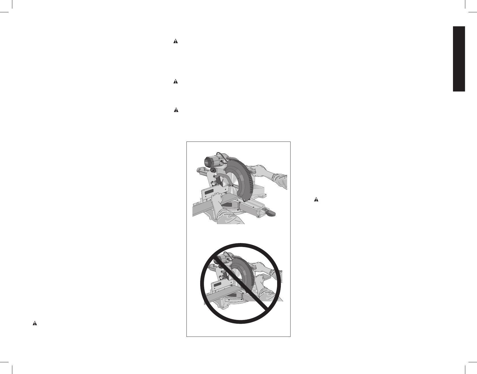
BODY AND HAND POSITION (FIG. 9A, 9B)
Proper positioning of your body and hands when operating
the miter saw will make cutting easier, more accurate and
safer. Never place hands near cutting area. Place hands no
closer than 6" (152 mm) from the blade. Hold the workpiece
tightly to the table and the fence when cutting. Keep hands
in position until the trigger has been released and the blade
has completely stopped. ALWAYS MAKE DRY RUNS
(UNPOWERED) BEFORE FINISH CUTS SO THAT YOU
CAN CHECK THE PATH OF THE BLADE. DO NOT CROSS
HANDS, AS SHOWN IN FIGURE 9B.
Keep both feet firmly on the floor and maintain proper
balance. As you move the miter arm left and right, follow it
and stand slightly to the side of the saw blade. Sight through
the guard louvers when following a pencil line.
CLAMPING THE WORKPIECE
WARNING: To reduce the risk of injury, turn unit off
and disconnect it from power source before installing
and removing accessories, before adjusting or when
making repairs. An accidental start-up can cause injury.
WARNING: A workpiece that is clamped, balanced and
secure before a cut may become unbalanced after a cut is
completed. An unbalanced load may tip the saw or anything
the saw is attached to, such as a table or workbench.
When making a cut that may become unbalanced, properly
support the workpiece and ensure the saw is firmly bolted to
a stable surface. Personal injury may occur.
WARNING: The clamp foot must remain clamped above
the base of the saw whenever the clamp is used. Always
clamp the workpiece to the base of the saw – not to any
other part of the work area. Ensure the clamp foot is not
clamped on the edge of the base of the saw.
CAUTION: Always use a work clamp to maintain control
and reduce the risk of workpiece damage and personal
injury, if your hands are required to be within 6" of the blade
during the cut.
If you cannot secure the workpiece on the table and against
the fence by hand (irregular shape, etc.), or your hand would
be less than 6" (152 mm) from the blade, a clamp or other
fixture must be used.
Use the material clamp provided with your saw. To purchase
the material clamp, contact your local retailer or D
e
WALT
service center.
Other aids such as spring clamps, bar clamps or C-clamps
may be appropriate for certain sizes and shapes of material.
Use care in selecting and placing these clamps. Take time to
make a dry run before making the cut. The left or right fence
will slide from side to side to aid in clamping.
TO INSTALL CLAMP
1. Insert it into the hole behind the fence. The clamp should
be facing toward the back of the miter saw. The groove
on the clamp rod should be fully inserted into the base.
Ensure this groove is fully inserted into the base of the
miter saw. If the groove is visible, the clamp will not be
secure.
2. Rotate the clamp 180º toward the front of the miter saw.
3. Loosen the knob to adjust the clamp up or down, then
use the fine adjust knob to firmly clamp the workpiece.
NOTE: Place the clamp on the opposite side of the base
when beveling. ALWAYS MAKE DRY RUNS (UNPOWERED)
BEFORE FINISH CUTS TO CHECK THE PATH OF THE
BLADE. ENSURE THE CLAMP DOES NOT INTERFERE
WITH THE ACTION OF THE SAW OR GUARDS.
ADJUSTMENTS
WARNING: To reduce the risk of injury, turn unit off
and disconnect it from power source before installing
and removing accessories, before adjusting or when
making repairs. An accidental start-up can cause injury.
Your miter saw is fully and accurately adjusted at the factory
at the time of manufacture. If readjustment due to shipping
and handling or any other reason is required, follow the
instructions below to adjust your saw.
Once made, these adjustments should remain accurate.
Take a little time now to follow these directions carefully to
maintain the accuracy of which your saw is capable.
MITER SCALE ADJUSTMENT (FIG. 5, 10)
Lock the arm in the down position. Unlock the miter lock
handle and swing the miter arm until the miter latch button
locks it at the 0° miter position. Do not lock the miter lock
handle. Place a square against the saw’s fence and blade,
as shown. (Do not touch the tips of the blade teeth with the
square. To do so will cause an inaccurate measure ment.)
If the saw blade is not exactly perpendicular to the fence,
loosen the four screws that hold the miter scale and move
the miter lock handle and the scale left or right until the blade
is perpendicular to the fence, as measured with the square.
Retighten the four screws. Pay no attention to the reading of
the miter pointer at this time.
PROPER CUT
FIG. 9A
IMPROPER CUT
FIG. 9B
English
10
MITER POINTER ADJUSTMENT (FIG. 5)
Unlock the miter lock handle to move the miter arm to the zero position. With the miter lock
handle unlocked, allow the miter latch to snap into place as you rotate the miter arm to zero.
Observe the miter pointer and miter scale shown in Figure 5. If the pointer does not indicate
exactly zero, loosen the miter pointer screw holding the pointer in place, reposition the pointer
and tighten the screw.
BEVEL SQUARE TO TABLE ADJUSTMENT (FIG. 4, 6, 11)
To align the blade square to the table, lock the arm in the down position with the lock down
pin. Place a square against the blade, ensuring the square is not on top of a tooth. Loosen
the bevel lock knob and ensure the arm is firmly against the 0° bevel stop. Rotate the 0° bevel
adjustment screw with the 1/2" (13 mm) blade wrench as necessary so that the blade is at 0°
bevel to the table, as measured with the square.
FIG. 10
MITER LOCK HANDLE
FIG. 11
MITER LOCK HANDLE
BEVEL POINTERS (FIG. 6)
If the bevel pointers do not indicate zero, loosen each screw that holds each bevel pointer in
place and move them as necessary. Ensure the 0° bevel is correct and the bevel pointers are
set before adjusting any other bevel angle screws.
BEVEL STOP 45º RIGHT AND LEFT ADJUSTMENT (FIG. 4, 6)
To adjust the right 45° bevel angle, loosen the bevel lock knob and pull the 0° bevel stop to
override the 0° bevel stop. When the saw is fully to the right, if the bevel pointer does not
indicate exactly 45°, turn the left 45° bevel adjustment screw with the 1/2" (13 mm) blade
wrench until the bevel pointer indicates 45°.
To adjust the left 45° bevel stop, first loosen the bevel lock knob and tilt the head to the left.
If the bevel pointer does not indicate exactly 45°, turn the right 45° bevel adjustment screw
until the bevel pointer reads 45°.
ADJUSTING THE BEVEL STOP TO 22.5° (OR 33.9°) (FIG. 4, 6)
NOTE: Adjust the bevel angles only after performing the 0° bevel angle and bevel pointer
adjustment.
To set the left 22.5° bevel angle, flip out the left 22.5° bevel pawl. Loosen the bevel lock knob
and tilt the head fully to the left. If the bevel pointer does not indicate exactly 22.5°, turn the
crown adjustment screw contacting the pawl with a 7/16" (10 mm) wrench until the bevel
pointer reads 22.5°.
To adjust the right 22.5° bevel angle, flip out the right 22.5° bevel pawl. Loosen the bevel lock
knob and pull the 0° bevel stop to override the 0° bevel stop. When the saw is fully to the
right, if the bevel pointer does not indicate exactly 22.5°, turn the crown adjustment screw
contacting the pawl with a 7/16" (10 mm) wrench until the bevel pointer indicates exactly
22.5°.
FENCE ADJUSTMENT (FIG. 4)
In order that the saw can bevel to many bevel positions, one of the fences may have to be
adjusted to provide clearance. To adjust each fence, loosen the fence adjustment knob and
slide the fence outward. Make a dry run with the saw turned off and check for clearance.
Adjust the fence to be as close to the blade as practical to provide max imum workpiece
support, without interfering with arm up and down movement. Tighten the fence adjustment
knob securely. When the bevel operations are complete, don’t forget to relocate the fence.
For certain cuts, it may be desirable to bring the fences closer to the blade. To use this feature,
back the fence adjustment knobs out two turns and move the fences closer to the blade past
the normal limit, then tighten the fence adjustment knobs to keep the fences in this location.
When using this feature, make a dry cut first to ensure the blade does not contact the fences.
NOTE: The tracks of the fences can become clogged with sawdust. If you notice that they are
becoming clogged, use a brush or some low pressure air to clear the guide grooves.
GUARD ACTUATION AND VISIBILITY (FIG. 4)
CAUTION: Pinch hazard. To reduce the risk of injury, keep thumb underneath the operating
handle when pulling the handle down. The lower guard will move up as the operating handle
is pulled down, which could cause pinching.
The lower guard on your saw has been designed to automatically uncover the blade when the
arm is brought down and to cover the blade when the arm is raised.
The guard can be raised by hand when installing or removing saw blades or for inspection
of the saw. NEVER RAISE THE LOWER GUARD MANUALLY UN LESS THE BLADE IS
STOPPED.
NOTE: Certain special cuts of large material will require that you manually raise the guard.
Refer to Cutting Large Material under Special Cuts.
The front section of the guard is louvered for visibility while cutting. Although the louvers
dramatically reduce flying debris, they are openings in the guard and safety glasses should
be worn at all times.
KERF PLATE ADJUSTMENT (FIG. 4)
To adjust the kerf plates, loosen the screws holding the kerf plates in place. Adjust so that the
kerf plates are as close as possible without interfering with the blade’s movement.
If a zero kerf width is desired, adjust the kerf plates as close to each other as possible. They
can now be cut slowly with the saw blade to give the smallest gap possible between the blade
and the kerf plates.
RAIL GUIDE ADJUSTMENT (FIG. 4)
Periodically check the rails for any play or clearance. The right rail can be adjusted with the
set screw shown in Figure4. To reduce clearance, use a 4 mm hex wrench and rotate the
set screw clockwise gradually while sliding the saw head back and forth. Reduce play while
maintaining minimum slide force.
MITER LOCK ADJUSTMENT (FIG. 12)
FIG. 12
MITER LOCK
ROD
LOCK NUT
The miter lock rod should be adjusted if the
table of the saw can be moved when the
miter lock handle is locked (down). To adjust
the miter lock, put the miter lock handle in the
unlocked (up) position. Using a 1/2" (13 mm)
open end wrench, loosen the lock nut on
the miter lock rod (Fig. 12). Using a slotted
screwdriver, tighten the miter lock rod by
turning it clockwise as shown in Figure 12.
Turn the lock rod until it is snug, then turn
English
11
counterclockwise one turn. To ensure the miter lock is functioning properly, re-lock the miter
lock to a non-detented measurement on the miter scale – for example, 34º – and make sure
the table will not rotate. Tighten lock nut.
Support for Long Pieces
WARNING: To reduce the risk of injury, turn unit off and disconnect it from
power source before installing and removing accessories, before adjusting or when
making repairs. An accidental start-up can cause injury.
ALWAYS SUPPORT LONG PIECES.
Never use another person as a substitute for a table extension, as additional support for a
workpiece that is longer or wider than the basic miter saw table or to help feed, support or
pull the workpiece.
For best results, use the DW7080 extension work support to extend the table width of your
saw, available from your dealer at extra cost. Support long workpieces using any convenient
means such as sawhorses or similar devices to keep the ends from dropping.
Cutting Picture Frames, Shadow Boxes And Other Four-
Sided Projects (Fig. 13, 14)
To best understand how to make the items listed here, we suggest that you try a few simple
projects using scrap wood until you develop a “feel” for your saw.
Your saw is the perfect tool for mitering corners like the one shown in Figure 13. Sketch A in
Figure 14 shows a joint made by using the bevel adjustment to bevel the edges of the two
boards at 45º each to produce a 90º corner. For this joint the miter arm was locked in the
zero position and the bevel adjustment was locked at 45º. The wood was positioned with the
broad flat side against the table and the narrow edge against the fence. The cut could also
be made by mitering right and left with the broad surface against the fence.
FIG. 13
A
FIG. 14
B
A
Cutting Trim Molding And Other Frames (Fig. 14)
Sketch B in Figure 14 shows a joint made by setting the miter arm at 45º to miter the two
boards to form a 90º corner. To make this type of joint, set the bevel adjustment to zero and
the miter arm to 45º. Once again, position the wood with the broad flat side on the table and
the narrow edge against the fence.
The two sketches in Figure 14 are for four-sided objects only.
As the number of sides changes, so do the miter and bevel angles. The chart below gives the
proper angles for a variety of shapes.
– EXAMPLES –
NUMBER OF SIDES MITER OR BEVEL ANGLE
4 45°
5 36°
6 30°
7 25.7°
8 22.5°
9 20°
10 18°
The chart assumes that all sides are of equal length. For a shape that is not shown in the
chart, use the following formula: 180º divided by the number of sides equals the miter (if the
material is cut vertically) or bevel angle (if the material is cut laying flat).
Cutting Compound Miters
FIG. 15
ANGLE “A”
(Fig. 15)
A compound miter is a cut made using a miter angle
and a bevel angle at the same time. This is the type of
cut used to make frames or boxes with slanting sides
like the one shown in Figure 15.
NOTE: If the cutting angle varies from cut to cut,
check that the bevel lock knob and the miter lock
handle are securely locked. These must be locked
after making any changes in bevel or miter.
The chart at the end of this manual (Table 1) will assist you in selecting the proper bevel and
miter settings for common compound miter cuts. To use the chart, select the desired angleA
(Fig. 15) of your project and locate that angle on the appropriate arc in the chart. From that
point follow the chart straight down to find the correct bevel angle and straight across to find
the correct miter angle.
Set your saw to the prescribed angles and make a few trial cuts. Practice fitting the cut pieces
together until you develop a feel for this procedure and feel comfortable with it.
Example: To make a 4-sided box with 26º exterior angles (Angle A, Fig. 15), use the upper
right arc. Find 26° on the arc scale. Follow the horizontal intersecting line to either side to
get miter angle setting on saw (42°). Likewise, follow the vertical intersecting line to the top
or bottom to get the bevel angle setting on the saw (18°). Always try cuts on a few scrap
pieces of wood to verify the settings on the saw.
Cutting Base Molding (Fig. 16)
ALWAYS MAKE A DRY RUN WITHOUT POWER BEFORE MAKING ANY CUTS.
Straight 90º cuts:
Position the wood against the fence and hold it in place as shown in Figure 16. Turn on
the saw, allow the blade to reach full speed and lower the arm smoothly through the cut.
CUTTING BASE MOLDING FROM 3" UP TO 6.75" (76 mm to 171 mm) HIGH
VERTICALLY AGAINST THE FENCE
NOTE: Use the slide lock lever, shown in Figure 7, when cutting base molding measuring from
3" to 6.75" (76 mm to 171 mm) high vertically against the fence.
Position material as shown in Figure 16.
All cuts should be made with the back of the molding against the fence and with the bottom
of the molding against the table.
English
12
INSIDE CORNER OUTSIDE CORNER
Left side
Miter left 45°
Save left side of cut
Miter right 45°
Save left side of cut
Right side
Miter right 45°
Save right side of cut
Miter left 45°
Save right side of cut
Material up to 6.75" (171 mm) can be cut as described above.
FIG. 16
Cutting Crown Molding
Your miter saw is well suited to the task of cutting crown molding. In order to fit properly,
crown molding must be compound mitered with extreme accuracy.
The two flat surfaces on a given piece of crown molding are at angles that, when added
together, equal exactly 90º. Most, but not all, crown molding has a top rear angle (the section
that fits flat against the ceiling) of 52º and a bottom rear angle (the part that fits flat against
the wall) of 38º.
Your miter saw has special pre-set miter latch points at 31.62º left and right for cutting crown
molding at the proper angle and bevel stop pawls at 33.9º left and right. There is also a mark
on the bevel scale at 33.9º.
The chart below gives the proper settings for cutting crown molding. (The numbers for
the miter and bevel settings are very precise and are not easy to accurately set on your
saw.) Since most rooms do not have angles of precisely 90º, you will have to fine tune your
settings anyway.
PRETESTING WITH SCRAP MATERIAL IS EXTREMELY IMPORTANT!
INSTRUCTIONS FOR CUTTING CROWN MOLDING LAYING FLAT AND USING THE
COMPOUND FEATURES
1. Molding should lay flat with broad back surface down on saw table (Fig. 17).
2. Top of molding against fence.
3. The settings below are for all standard (U.S.) crown molding with 52° and 38° angles.
INSIDE CORNER OUTSIDE CORNER
Left side
Bevel left 33.9°
Miter table set at right 31.62°
Save left end of cut
Bevel right 33.9°
Miter table set at left 31.62°
Save left end of cut
Right side
Bevel right 33.9°
Miter table set at left 31.62°
Save right end of cut
Bevel left 33.9°
Miter table set at right 31.62°
Save right end of cut
When setting bevel and miter angles for all compound miters, remember that:
The angles presented for crown moldings are very precise and difficult to set exactly. Since
they can easily shift slightly and very few rooms have exactly square corners, all settings
should be tested on scrap molding.
FIG. 17
FENCE
TABLE
CROWN MOLDING FLAT ON TABLE
AND AGAINST FENCE
CROWN MOLDING BETWEEN
FENCE AND TABLE
TABLE
FENCE
BOTTOM SIDE
OF MOLDING
TOP SIDE
OF MOLDING
FIG. 18
DW7084
CROWN
MOLDING
FENCE
PRETESTING WITH SCRAP MATERIAL IS EXTREMELY IMPORTANT!
ALTERNATIVE METHOD FOR CUTTING CROWN MOLDING
Place the molding on the table at an angle between the fence and the saw table, as shown
in Figure 18. Use of the crown molding fence accessory (DW7084) is highly recommended
because of its degree of accuracy and convenience (Fig. 1). The crown molding fence
accessory is available for purchase from your local dealer.
The advantage to cutting crown molding using this method is that no bevel cut is required.
Minute changes in the miter angle can be made without affecting the bevel angle. This way,
when corners other than 90º are encountered, the saw can be quickly and easily adjusted
for them. Use the crown molding fence accessory to maintain the angle at which the molding
will be on the wall.
INSTRUCTIONS FOR CUTTING CROWN MOLDING ANGLED BETWEEN THE
FENCE AND BASE OF THE SAW FOR ALL CUTS
1. Angle the molding so the bottom of the molding (part which goes against the wall when
installed) is against the fence and the top of the molding is resting on the saw table, as
shown in Figure 18.
2. The angled “flats” on the back of the molding must rest squarely on the fence and saw
table.
INSIDE CORNER OUTSIDE CORNER
Left side
Miter right at 45°
Save right side of cut
Miter left at 45°
Save right side of cut
Right side
Miter left at 45°
Save left side of cut
Miter right at 45°
Save left side of cut
English
13
Special Cuts
NEVER MAKE ANY CUT UNLESS THE MATERIAL IS SECURED ON THE TABLE AND
AGAINST THE FENCE.
ALUMINUM CUTTING (FIG. 19, 20)
ALWAYS USE THE APPROPRIATE SAW BLADE MADE ESPECIALLY FOR CUTTING
ALUMINUM. These are available at your local D
e
WALT retailer or D
e
WALT service center.
Certain workpieces, due to their size, shape or surface finish, may require the use of a clamp
or fixture to prevent movement during the cut. Position the material so that you will be cutting
the thinnest cross section, as shown in Figure 19. Figure 20 illustrates the wrong way to cut
these extrusions.
Use a stick wax cutting lubricant when cutting aluminum. Apply the stick wax cutting lubricant
directly to the saw blade before cutting. Never apply stick wax to a moving blade. The
wax, available at most hardware stores and industrial mill supply houses, provides proper
lubrication and keeps chips from adhering to the blade.
Be sure to properly secure workpiece.
Refer to Saw Blades under Optional Accessories for correct saw blade.
BOWED MATERIAL (FIG. 21, 22)
When cutting bowed material always position it as shown in Figure 21 and never like that
shown in Figure 22. Positioning the material incorrectly will cause it to pinch the blade near
the completion of the cut.
CUTTING PLASTIC PIPE OR OTHER ROUND MATERIAL
Plastic pipe can be easily cut with your saw. It should be cut just like wood and CLAMPED
OR HELD FIRMLY TO THE FENCE TO KEEP IT FROM ROLLING. This is extremely
important when making angle cuts.
CUTTING LARGE MATERIAL (FIG. 23)
Occasionally you will encounter a piece of wood a little too large to fit beneath the lower
guard. If this occurs, simply place your right thumb on the upper side of the guard and roll
the guard up just enough to clear the workpiece, as shown in Figure 23. Avoid doing this
as much as possible, but if need be, the saw will operate properly and make the bigger cut.
NEVER TIE, TAPE, OR OTHERWISE HOLD THE GUARD OPEN WHEN OPERATING THIS
SAW.
SPECIAL SET-UP FOR WIDE CROSSCUTS (FIG. 24, 25)
Your saw can cut very wide (up to 16.1"
FIG. 25
BASE FENCE
[409 mm]) workpieces when a special
set-up is used. To set the saw up for
these workpieces, follow these steps:
1. Remove both left and right sliding
fences from the saw and set aside.
To remove them, unscrew the fence
adjustment knobs several turns and
slide each fence outward. Adjust and
lock the miter control so that it is at
0º miter.
2. Make a platform using a piece of
1.5" (38 mm) thick particleboard or
similar flat strong 1.5" thick wood to
the dimensions: 14.5" x 26" (368 x
660 mm). The platform must be flat,
otherwise the material could move
during cutting and cause injury.
FIG. 21
CORRECT
FIG. 22
INCORRECT
FIG. 19
BLADE
CORRECT
FENCE
INCORRECT
FIG. 20
BLADE
FENCE
FIG. 23
SCREWS
(two each side)
FIG. 24
English
14
3. Mount the 14.5" x 26" (368 x 660 mm) platform to the saw using four 3" (76.2 mm) long
wood screws through the holes in the base fence (Fig. 24). Four screws must be used
to properly secure the material. When the special set-up is used, the platform will be cut
into two pieces. Ensure the screws are tightened properly, otherwise material could loosen
and cause injury. Ensure the platform is firmly flat on the table, against the fence, and
centered evenly from left to right.
WARNING: Ensure the saw is mounted firmly to a stable flat surface. Failure to do so
could cause the saw to be unstable and fall causing personal injury.
4. Place the workpiece to be cut on top of the platform mounted to the table. Ensure the
workpiece is firmly against the back of the base fence (Fig. 25).
5. Secure the material before cutting. Cut slowly through the material using a out-down-and-
back motion. Failure to clamp securely or cut slowly could result in the material coming
loose and causing injury.
After several cuts are made at various miter angles other than 0º, the platform may weaken
and not properly support the work. Install a new, unused platform to the saw after presetting
the desired miter angle.
CAUTION: Continued use of a platform with several kerfs may cause loss of material
control and possible injury.
MAINTENANCE
WARNING: To reduce the risk of injury, turn unit off and disconnect it from
power source before installing and removing accessories, before adjusting or when
making repairs. An accidental start-up can cause injury.
WARNING: To reduce the risk of serious personal injury, DO NOT touch the sharp
points on the blade with fingers or hands while performing any maintenance.
DO NOT use lubricants or cleaners (particularly spray or aerosol) in the vicinity of the plastic
guard. The polycarbonate material used in the guard is subject to attack by certain chemicals.
• All bearings are sealed. They are lubricated for life and need no further maintenance.
Periodically clean all dust and wood chips from around AND UNDER the base and the
rotary table. Even though slots are provided to allow debris to pass through, some dust
will accumulate.
• The brushes are designed to give you several years of use. If they ever need
replacement follow the instructions under Brushes or return the tool to the nearest
service center for repair.
Removing and Replacing Belt (Fig.4, 26)
The belt is designed to last the life of the
SET
SCREW
SCREWS
FIG. 26
tool. However, abuse of the tool could
cause the belt to fail.
If the blade does not turn when the motor
is running, the belt has failed. To inspect
or replace the belt, remove the belt cover
screws. Remove the belt cover. Inspect
the ribs of the belt for wear or failure.
Check belt tension by squeezing the belt as
shown in Figure 26. The belt halves should
almost touch when squeezing firmly with
the thumb and index finger. To adjust the
tension, loosen, but do not remove, the
four crosshead screws shown. Then rotate
the set screw on the top of the motor
plate casting until the proper tension is
achieved. Tighten the four screws securely
and replace the belt cover.
NOTICE: Overtightening the belt will cause premature motor failure.
Dust Duct Cleaning
Depending on your cutting environment, saw dust can clog the dust duct and may prevent
dust from flowing away from the cutting area properly. With the saw unplugged and the saw
head raised fully, low pressure air or a large diameter dowel rod can be used to clear the dust
out of the dust duct.
Brushes
WARNING: To reduce the risk of injury, turn unit off and disconnect it from
power source before installing and removing accessories, before adjusting or when
making repairs. An accidental start-up can cause injury.
Inspect carbon brushes regularly by unplugging tool, removing the motor endcap (Fig. 4),
lifting the brush spring and withdrawing the brush assembly. Keep brushes clean and sliding
freely in their guides. Always replace a used brush in the same orientation in the holder as it
was prior to its removal. If the brushes are worn down to approximately 1/2" (12.7 mm), the
springs will no longer exert pressure and they must be replaced. Use only identical D
e
WALT
brushes. Use of the correct grade of brush is essential for proper operation of electric brake.
New brush assemblies are available at D
e
WALT service centers. The tool should be allowed
to “run in” (run at no load) for 10 minutes before use to seat new brushes. The electric brake
may be erratic in operation until the brushes are properly seated (worn in). Always replace the
brush inspection cap after inspection or servicing the brushes.
While “running in” DO NOT TIE, TAPE, OR OTHER WISE LOCK THE TRIGGER SWITCH ON.
HOLD BY HAND ONLY.
Cleaning
WARNING: Blow dirt and dust out of all air vents with clean, dry air at least once a week.
To minimize the risk of eye injury, always wear ANSI Z87.1 approved eye protection when
performing this.
WARNING: Never use solvents or other harsh chemicals for cleaning the non-metallic parts
of the tool. These chemicals may weaken the plastic materials used in these parts. Use a
cloth dampened only with water and mild soap. Never let any liquid get inside the tool; never
immerse any part of the tool into a liquid.
Accessories
WARNING: Since accessories, other than those offered by D
e
WALT, have not been tested
with this product, use of such accessories with this tool could be hazardous. To reduce the
risk of injury, only D
e
WALT recommended accessories should be used with this product.
Recommended accessories for use with your tool are available at extra cost from your local
dealer or authorized service center. If you need assistance in locating any accessory, please
contact D
e
WALT Industrial Tool Co., 701 East Joppa Road, Baltimore, MD 21286, call
1-800-4-D
e
WALT (1-800-433-9258) or visit our website: www.dewalt.com.
Repairs
To assure product SAFETY and RELIABILITY, repairs, maintenance and adjustment (including
brush inspection and replacement) should be performed by a D
e
WALT factory service center,
a D
e
WALT authorized service center or other qualified service personnel. Always use identical
replacement parts.
Register Online
Thank you for your purchase. Register your product now for:
WARRANTY SERVICE: Registering your product will help you obtain more efficient
warranty service in case there is a problem with your product.
CONFIRMATION OF OWNERSHIP: In case of an insurance loss, such as fire, flood or
theft, your registration of ownership will serve as your proof of purchase.
English
15
FOR YOUR SAFETY: Registering your product will allow us to contact you in the unlikely
event a safety notification is required under the Federal Consumer Safety Act.
Register online at www.dewalt.com/register.
Three Year Limited Warranty
D
e
WALT will repair, without charge, any defects due to faulty materials or workmanship for
three years from the date of purchase. This warranty does not cover part failure due to normal
wear or tool abuse. For further detail of warranty coverage and warranty repair information,
visit www.dewalt.com or call 1-800-4-D
e
WALT (1-800-433-9258). This warranty does not
apply to accessories or damage caused where repairs have been made or attempted by
others. This warranty gives you specific legal rights and you may have other rights which vary
in certain states or provinces.
In addition to the warranty, D
e
WALT tools are covered by our:
1 YEAR FREE SERVICE
D
e
WALT will maintain the tool and replace worn parts caused by normal use, for free, any time
during the first year after purchase.
90 DAY MONEY BACK GUARANTEE
If you are not completely satisfied with the performance of your D
e
WALT Power Tool, Laser, or
Nailer for any reason, you can return it within 90 days from the date of purchase with a receipt
for a full refund – no questions asked.
LATIN AMERICA: This warranty does not apply to products sold in Latin America. For
products sold in Latin America, see country specific warranty information contained in the
packaging, call the local company or see website for warranty information.
FREE WARNING LABEL REPLACEMENT: If your warning labels become illegible or are
missing, call 1-800-4-D
e
WALT (1-800-433-9258) for a free replacement.
Troubleshooting Guide
BE SURE TO FOLLOW SAFETY RULES AND INSTRUCTIONS
TROUBLE! WHAT’S WRONG? WHAT TO DO
Saw will not
start
1. Saw not plugged in 1. Plug in saw.
2. Fuse blown or circuit
breaker tripped
2. Replace fuse or reset circuit breaker.
3. Cord damaged 3. Have cord replaced by authorized
service center.
4. Brushes worn out 4. Have brushes replaced by authorized
service center or replace them yourself.
Refer to Brushes.
Saw makes
unsatisfactory
cuts
1. Dull blade 1. Replace blade. Refer to Changing or
Installing a New Saw Blade.
2. Blade mounted
backwards
2. Turn blade around. Refer to Changing
or Installing a New Saw Blade.
3. Gum or pitch on
blade
3. Remove blade and clean with coarse
steel wool and turpentine or household
oven cleaner.
4. Incorrect blade for
work being done
4. Change the blade type. Refer to Saw
Blades under Optional Accessories.
Blade does not
come up to
speed
1. Extension cord too
light or too long
1. Replace with adequate size cord. Refer
to Use Proper Extension Cord under
Important Safety Instructions.
2. Low house current 2. Contact your electric company.
Machine
vibrates
excessively
1. Saw not mounted
securely to stand or
work bench
1. Tighten all mounting hardware. Refer to
Bench Mounting.
2. Stand or bench on
uneven floor
2. Reposition on flat level surface. Refer to
Familiarization.
3. Damaged saw blade 3. Replace blade. Refer to Changing or
Installing a New Saw Blade.
Does not make
accurate
miter cuts
1. Miter scale not
adjusted correctly
1. Check and adjust. Refer to Miter Scale
Adjustment under Adjustments.
2. Blade is not square
to fence
2. Check and adjust. Refer to Miter Scale
Adjustment under Adjustments.
3. Blade is not
perpendicular to
table
3. Check and adjust fence. Refer to Bevel
Square to Table Adjustment under
Adjustments.
4. Workpiece moving 4. Clamp workpiece securely to fence or
glue 120 grit sandpaper to fence with
rubber cement.
Material
pinches blade
1. Cutting bowed
material
1. Refer to Bowed Material under
Special Cuts.
English
16
TABLE 1: COMPOUND MITER CUT
(POSITION WOOD WITH BROAD FLAT SIDE ON THE TABLE AND THE NARROW EDGE AGAINST THE FENCE)
SET THIS MITER ANGLE ON SAW
ANGLE OF SIDE OF BOX (ANGLE A)
SQUARE BOX
6-SIDED BOX
SET THIS BEVEL ANGLE ON SAW
8-SIDED BOX
17
Français
Définitions: lignes directrices en
matière de sécurité
Les définitions ci-dessous décrivent le niveau de danger pour chaque
mot-indicateur employé. Lire le mode d’emploi et porter une attention particulière à ces
symboles.
DANGER: indique une situation dangereuse imminente qui, si elle n’est pas évitée,
entraînera la mort ou des blessures graves.
AVERTISSEMENT : indique une situation potentiellement dangereuse qui, si elle
n’est pas évitée, pourrait entraîner la mort ou des blessures graves.
ATTENTION: indique une situation potentiellement dangereuse qui, si elle n’est pas
évitée, pourrait entraîner des blessures légères ou modérées.
AVIS : indique une pratique ne posant aucun risque de dommages corporels mais
qui par contre, si rien n’est fait pour l’éviter, pourrait poser des risques de dommages
matériels.
POUR TOUTE QUESTION OU REMARQUE AU SUJET DE CET OUTIL OU DE TOUT AUTRE
OUTIL D
e
WALT, COMPOSEZ LE NUMÉRO SANS FRAIS : 1-800-4-D
e
WALT (1-800-433-
9258).
AVERTISSEMENT : afin de réduire le risque de blessures, lire le mode d’emploi de
l’outil.
Avertissements de sécurité généraux pour les outils
électriques
AVERTISSEMENT ! Lire tous les avertissements de sécurité et toutes les
directives. Le non-respect des avertissements et des directives pourrait se solder par
un choc électrique, un incendie et/ou une blessure grave.
CONSERVER TOUS LES AVERTISSEMENTS ET TOUTES
LES DIRECTIVES POUR UN USAGE ULTÉRIEUR
Double isolation
Afin de protéger l’utilisateur contre les décharges électriques, les outils à double isolation sont
complètement recouverts de deux couches distinctes d’isolant électrique ou d’une simple
épaisseur renforcée de matière isolante. Les outils comportant ce système d’isolation ne sont
pas conçus pour être mis à la terre. L’outil est donc doté d’une prise à deux broches qui
permet d’utiliser des rallonges sans avoir à se soucier de maintenir une connexion à la terre.
REMARQUE : le fait que cet outil soit muni d’une double isolation ne signifie pas que
l’utilisateur peut cesser de respecter les consignes de sécurité qui s’imposent. L’isolation
secondaire offre une protection contre tout dommage corporel pouvant résulter d’une
défaillance électrique possible du système primaire d’isolation interne.
ATTENTION : EN CAS DE RÉPARATION, UTILISER UNIQUEMENT DES PIÈCES DE
RECHANGE IDENTIQUES. Réparer ou remplacer les cordons d’alimentation endommagés.
Fiches polarisées
Certains appareils comportent des fiches polarisées (c’est-à-dire qu’une lame est plus large
que l’autre) afin de réduire le risque de choc électrique. Lorsqu’elle est présente, cette fiche ne
se branche que d’une seule façon dans une prise de courant polarisée. Si la fiche ne s’insère
pas totalement dans la prise de courant, l’inverser. Si elle ne s’insère toujours pas dans la
prise, demander à un électricien compétent d’installer une fiche polarisée. Ne pas remplacer
la fiche.
Entraînement
Moteur 120 Volt
Puissance d’entrée : 1600 Moteur 15 ampères
3 800 tr/min Engrenages hélicoïdaux taillés
Courroie trapézoïdale multiple Roulements à rouleau
Frein électrique automatique Lame en carbure
Consignes de sécurité pour tous les outils
Cette scie à onglets est compatible avec la lampe de travail et le laser D
e
WALT.
AVERTISSEMENT : TOUJOURS utiliser une protection oculaire lors de l’utilisation
de la scie à onglets pour réduire le risque de blessures aux yeux.
MAINTENIR LE PROTÈGE-LAME EN PLACE et en état de fonctionnement.
RETIRER LES CLÉS À MOLETTE ET LES CLÉS DE RÉGLAGE. S’habituer à vérifier
si les clés à molette et les clés de réglage sont retirées de la broche avant de mettre l’outil
sous tension. Des outils, des déchets de découpe et d’autres débris peuvent être projetés
à grande vitesse, provoquant des blessures.
GARDER LA ZONE DE TRAVAIL PROPRE. Les zones et établis encombrés sont
souvent des causes d’accidents.
NE PAS UTILISER L’APPAREIL DANS UN ENVIRONNEMENT DANGEREUX.
L’utilisation d’outils électriques dans des endroits humides ou mouillés ou sous la pluie peut
provoquer un choc électrique ou une électrocution. Tenir la zone de travail bien éclairée
pour éviter de trébucher ou de mettre bras, mains et doigts en danger.
TENIR LES ENFANTS À L’ÉCART. Tous les visiteurs doivent se trouver à une distance
sûre de la zone de travail. Un atelier représente un environnement potentiellement
dangereux.
S’ASSURER QUE L’ATELIER NE PRÉSENTE PAS DE DANGER POUR LES
ENFANTS : utiliser des cadenas, des interrupteurs principaux ou retirer les clés de
démarrage. Le démarrage non autorisé d’un appareil par un enfant ou un visiteur pourrait
se solder par des blessures.
NE PAS FORCER L’OUTIL. Le travail sera mieux accompli et sera moins dangereux au
rythme prévu pour l’appareil.
UTILISER L’OUTIL APPROPRIÉ. Ne pas forcer un outil ou un accessoire pour effectuer
un travail auquel il n’a pas été conçu. L’utilisation d’un outil ou d’un accessoire inapproprié
pourrait se solder par des blessures corporelles.
PORTER LES VÊTEMENTS APPROPRIÉS. Éviter vêtements amples, gants, cravates,
bagues, bracelets ou autres bijoux qui pourraient se prendre dans les pièces mobiles. Il est
recommandé de porter des chaussures antidérapantes. Couvrir ou attacher les cheveux
longs
TOUJOURS PORTER DES LUNETTES DE SÉCURITÉ. Les lunettes ordinaires
ne constituent PAS des lunettes de sécurité. Utiliser également un masque facial ou
antipoussière si l’opération de découpe génère de la poussière. TOUJOURS PORTER
UN ÉQUIPEMENT DE SÉCURITÉ HOMOLOGUÉ :
protection oculaire conforme à la norme ANSI Z87.1 (CAN/CSA Z94.3) ;
protection auditive conforme à la norme ANSI S12.6 (S3.19) ;
protection des voies respiratoires conforme aux normes NIOSH/OSHA/MSHA.
FIXER LA PIÈCE. Utiliser des brides de fixation ou un étau pour maintenir la pièce sur la
table et contre le guide. Faire de même lorsque le travail à effectuer exigera que la main de
l’opérateur se trouve très proche de la lame (à moins de 152 mm [6 po]). Une telle pratique
est plus sécuritaire, car l’opérateur peut utiliser ses deux mains pour faire fonctionner l’outil.
NE PAS TROP TENDRE LES BRAS. Conserver son équilibre en tout temps. Une perte
d’équilibre risque d’entraîner une blessure corporelle.
PRENDRE SOIN DES OUTILS. S’assurer que les outils sont aiguisés et propres afin
d’optimiser sécurité et performance. Suivre les consignes de graissage et de changement
18
Français
d’accessoires. Les machines et outils mal entretenus peuvent s’endommager davantage
et/ou provoquer des blessures.
ÉTEINDRE L’APPAREIL ET COUPER LE COURANT avant d’installer ou de retirer
des accessoires, avant de réaliser ou de modifier un réglage et lors de réparations ou de
déplacements de l’appareil. Un démarrage accidentel peut provoquer des blessures. Ne
pas toucher aux lames métalliques de la fiche lors du branchement ou du débranchement
du cordon d’alimentation.
RÉDUIRE LE RISQUE DE DÉMARRAGE ACCIDENTEL. S’assurer que l’interrupteur
se trouve sur la position « ARRÊT » avant de brancher le cordon d’alimentation.
UTILISER UNE RALLONGE APPROPRIÉE. S’assurer que la rallonge est en bon état.
Lorsqu’une rallonge est utilisée, s’assurer d’utiliser un calibre suffisamment élevé pour
assurer le transport du courant nécessaire au fonctionnement de l’appareil. Une rallonge
de calibre inférieur causera une chute de tension de ligne et donc une perte de puissance
et une surchauffe. Le tableau suivant indique le calibre approprié à utiliser selon la longueur
de la rallonge et l’intensité nominale de la plaque signalétique. En cas de doute, utiliser le
calibre supérieur suivant. Plus le numéro de calibre est petit, plus le cordon est de calibre
élevé.
Calibre minimum pour rallonge
Intensité nominale
Volts
Longueur totale du cordon
en mètres (en pieds)
120 V 7,6 (25) 15,2 (50) 30,5 (100) 45,7 (150)
240 V 15,2 (50) 30,5 (100) 61,0 (200) 91,4 (300)
Plus de Pas plus de AWG
0 6 5,5 (18) 4,9 (16) 4,9 (16) 4,3 (14)
6 10 5,5 (18) 4,9 (16) 4,3 (14) 3,7 (12)
10 12 4,9 (16) 4,9 (16) 4,3 (14) 3,7 (12)
12 16 4,3 (14) 3,7 (12) Non recommandé
VÉRIFIER QUE LES PIÈCES NE SONT PAS ENDOMMAGÉES. Avant toute
utilisation ultérieure de l’outil, un protège-lame (ou une autre pièce) endommagé doit être
soigneusement examiné afin de déterminer s’il fonctionnera correctement et remplira
sa fonction prévue – vérifier l’alignement des pièces mobiles, la présence de grippage
des pièces mobiles, de rupture de pièces, la fixation et tout problème pouvant nuire au
fonctionnement de l’outil. Un protège-lame (ou toute autre pièce) endommagé doit être
réparé et remplacé adéquatement. Ne pas utiliser l’appareil si l’interrupteur ne fonctionne
pas.
UTILISER LES ACCESSOIRES RECOMMANDÉS. N’utiliser que les accessoires
conseillés par le fabricant pour le modèle de l’outil. Des accessoires qui conviennent à
un outil pourraient être dangereux lorsqu’ils sont utilisés avec un autre outil. Une liste des
accessoires recommandés se trouve dans le mode d’emploi. L’utilisation d’accessoires
incorrects peut entraîner un risque de blessure corporelle.
NE JAMAIS SE TENIR SUR L’OUTIL. Une blessure grave pourrait se produire en cas
de basculement de l’outil ou de démarrage accidentel de l’outil de découpe.
NE JAMAIS LAISSER L’OUTIL FONCTIONNER SANS SURVEILLANCE. ÉTEINDRE
L’APPAREIL. Ne pas laisser l’outil tant qu’il n’est pas complètement arrêté. De graves
blessures pourraient survenir.
NE PAS UTILISER D’OUTILS ÉLECTRIQUES À PROXIMITÉ DE LIQUIDES
INFLAMMABLES OU DANS UNE ATMOSPHÈRE GAZEUSE OU EXPLOSIVE. Les
moteurs de ces outils peuvent provoquer des étincelles et enflammer des vapeurs.
ÊTRE VIGILANT, SURVEILLER LE TRAVAIL EFFECTUÉ ET FAIRE PREUVE DE
JUGEMENT. NE PAS UTILISER L’APPAREIL EN CAS DE FATIGUE OU SOUS
L’INFLUENCE DE DROGUES, D’ALCOOL OU DE MÉDICAMENTS. En effet, un
moment d’inattention en utilisant des outils électriques peut se solder par des blessures.
Règles de sécurité supplémentaires pour les scies
à onglets
AVERTISSEMENT : ne pas laisser une bonne connaissance de l’outil (acquise par
l’utilisation fréquente de la scie) prendre préséance sur les règles de sécurité. Toujours se
souvenir qu’une fraction de seconde d’imprudence est suffisante pour infliger de graves
blessures.
NE PAS FAIRE FONCTIONNER CET APPAREIL avant qu’il ne soit entièrement
assemblé et installé conformément aux directives. Un appareil mal assemblé peut
provoquer des blessures graves.
DEMANDER CONSEIL à un superviseur, à un instructeur ou à toute autre personne
qualifiée si l’on ne maîtrise pas parfaitement l’utilisation de cet appareil. La connaissance
est synonyme de sécurité.
STABILITÉ. S’assurer que la scie à onglets est posée sur une surface portante fixe et ne
risque pas de glisser ou de se déplacer durant son utilisation.
SUIVRE TOUS LES CODES DE CÂBLAGE et les branchements électriques
recommandés afin d’éviter les chocs électriques ou l’électrocution. Il faut protéger la ligne
d’alimentation électrique avec un fusible à temporisation ou un disjoncteur d’au moins
15 ampères.
S’ASSURER que la lame tourne dans le bon sens. Les dents de la lame doivent pointer
dans le sens de rotation, comme il est indiqué sur la scie.
SERRER TOUTES LES POIGNÉES DE FIXATION, les boutons et les leviers avant
l’utilisation de la scie. Si les brides sont lâches, des pièces ou la pièce à travailler pourraient
être projetées à grande vitesse.
S’ASSURER QUE la lame au complet et les attaches de lame sont propres, que les côtés
encastrés des attaches de lame sont appuyés sur la lame et que la vis de l’arbre est bien
serrée. Un mécanisme de serrage de lame lâche ou mal installé risque d’endommager la
scie et de provoquer des blessures corporelles.
UTILISER TOUJOURS UNE LAME TRANCHANTE. Vérifier que la lame fonctionne
bien dans l’axe et qu’elle ne vibre pas. Une lame émoussée ou une lame qui vibre peut
endommager l’appareil et/ou provoquer des blessures graves.
NE PAS UTILISER UNE TENSION AUTRE QUE CELLE DÉSIGNÉE pour la scie.
Une tension autre risquerait d’entraîner une surchauffe, des dommages à la scie et des
blessures corporelles.
NE PAS PLACER QUOI QUE CE SOIT CONTRE LE VENTILATEUR pour retenir
l’arbre moteur. Une telle pratique peut endommager l’outil et entraîner des blessures
corporelles.
NE PAS FORCER L’ACTION DE COUPE. Le calage partiel ou complet du moteur peut
causer des dommages à l’appareil ou à la lame et/ou des blessures graves.
LAISSER LE MOTEUR ATTEINDRE SON PLEIN RÉGIME avant de commencer
la coupe. Commencer à couper trop tôt peut endommager l’appareil ou la lame et/ou
provoquer des blessures graves.
NE JAMAIS COUPER DE MÉTAUX FERREUX (métaux contenant du fer ou de l’acier)
ni de la maçonnerie. En coupant l’un ou l’autre de ces matériaux, les pointes carburées
peuvent se détacher de la lame, et ce, à grande vitesse. Cela peut provoquer des
blessures graves.
NE PAS UTILISER DE MEULES ABRASIVES. La chaleur excessive et les particules
abrasives qu’elles produisent risquent d’endommager la scie et de causer des blessures
corporelles.
AUCUNE PARTIE DU CORPS NE DOIT SE TROUVER DANS LA TRAJECTOIRE
DE LA LAME DE LA SCIE. Un tel positionnement risque d’entraîner des blessures
corporelles.
1 / 1

DeWalt DWS709 Owner's manual

Category
Power tools
Type
Owner's manual

Ask a question and I''ll find the answer in the document

Finding information in a document is now easier with AI

Ask the document