
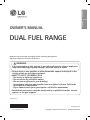
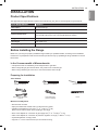
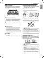
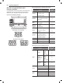
ENGLISH ESpañoL
MFL68920525_02
OWNER’S MANUAL
DUAL FUEL RANGE
Read this owner’s manual thoroughly before operating the appliance
and keep it handy for reference at all times.
•
Do not store or use gasoline or other flammable vapors and liquids in the
vicinity of this or any other appliance.
•
WHAT TO DO IF YOU SMELL GAS
- Do not try to light any appliance.
- Do not touch any electrical switch.
- Do not use any phone in your building.
- Immediately call your gas supplier from a neighbor's phone. Follow the
gas supplier's instructions.
- If you cannot reach your gas supplier, call the fire department.
•
Installation and service must be performed by a qualified installer, service
agency, or the gas supplier.
If the information in this manual is not followed exactly, a fire or explosion
may result causing property damage, personal injury or death.
WARNING
LSD4913**
www.lg.com
Copyright © 2018 LG Electronics Inc. All Rights Reserved.

2
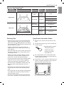
TABLE OF CONTENTS
TABLE OF CONTENTS
3
PRODUCT FEATURES
4
IMPORTANT SAFETY
INSTRUCTIONS
12
PRODUCT OVERVIEW
12 Parts
12 Accessories
13
INSTALLATION
13 Product Specifications
13 Before Installing the Range
14 Installing the Range
15 Dimensions and Clearances
16 Optional Rear Filler
17 Providing Adequate Gas Supply
18 Connecting the Range to Gas
19 Connecting Electricity
22 Assembling the Surface Burners
22 Checking Ignition of the Surface Burners
23 Leveling the Range
23 Engaging the Anti-tip Device
24
OPERATION
24 Gas Surface Burners
25 Burner Locations
25 Using the Gas Surface Burners
25 Setting the Flame Size
26 In Case of Power Failure
26 Range-Top Cookware
26 Using a Wok
27 Using Stove-Top Grills
27 Using the Griddle
28 The Oven
29 Control Panel Overview
30 Changing Oven Settings
30 Clock
30 Oven Light
30 Minimum & Maximum Default Settings
31 Timer On/Off
31 Settings
-
Setting the Hour Mode
-
Setting Convection Auto Conversion
-
Adjusting the Oven Thermostat
-
Turning the Preheat Alarm Light On/Off
-
Adjusting the Beeper Volume
-
Selecting Fahrenheit or Celsius
32 Lockout
33 Start Time (Delayed Timed Cook)
33 Cook Time (Timed Cook)
34 Bake
35 Convection Mode
36 Recommended Baking and Roasting Guide
37 Broil
38 Recommended Broiling Guide
39 Warm
39 Proof
39 Speed Roast
40 Remote Start
40 Sabbath Mode
41
SMART FUNCTIONS
41 LG SmartThinQ Application
42 Smart Diagnosis™ Function
44 FCC Notice (For transmitter module contained in
this product)
44 FCC RF Radiation Exposure Statement
45
MAINTENANCE
45 Removing and Replacing the Gas Surface
Burners
47 Cleaning the Exterior
48 Door Care Instructions
48 EasyClean
®
51 Self Clean
53 Changing the Oven Light
53 Removing and Replacing the Lift-Off Oven
Doors and Drawer
55
TROUBLESHOOTING
55 FAQs
57 Before Calling for Service
60
LIMITED WARRANTY

3
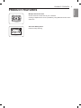
PRODUCT FEATURES
ENGLISH
PRODUCT FEATURES
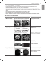
Multiple Gas Burner Sizes
Choose a burner to fit the size of your cookware.
Cooking multiple items at once is possible by using different burners at the
same time.
Self Clean & EasyClean
®
Useful for easy cleaning.

4
IMPORTANT SAFETY INSTRUCTIONS
IMPORTANT SAFETY INSTRUCTIONS
Read and follow all instructions when using the range to prevent the risk of fire, electric
shock, personal injury, or damage. This guide does not cover all possible conditions that
may occur. Always contact your service agent or manufacturer about problems that you do
not understand.
Download this owner's manual at: http://www.lg.com
This is the safety alert symbol. This symbol alerts you to potential hazards that
can result in property damage and/or serious bodily harm or death.
All safety messages will follow the safety alert symbol and either the word
WARNING or CAUTION. These words mean:
WARNING
-
Indicates a hazardous situation which, if not avoided, could result
in death or serious injury.
CAUTION
-
Indicates a hazardous situation which, if not avoided, could result
in minor or moderate injury.
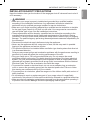
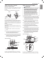
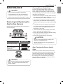
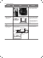
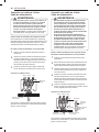
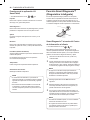
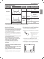
ANTI-TIP DEVICE
WARNING
•
TO REDUCE THE RISK OF TIPPING, THE APPLIANCE MUST BE SECURED
BY A PROPERLY INSTALLED ANTI-TIP DEVICE. TO CHECK IF THE DEVICE IS
INSTALLED PROPERLY, VERIFY THAT THE ANTI-TIP DEVICE IS ENGAGED, OR
GRASP THE TOP REAR EDGE OF THE RANGE BACK GUARD AND CAREFULLY
ATTEMPT TO TILT IT FORWARD. Refer to the installation section for instructions.
•
A child or adult can tip the range and be killed.
•
Install the anti-tip device to the structure and/or the range. Verify the anti-tip device
has been properly installed and engaged by following the guide of the Anti tip bracket
template.
•
Engage the range to the anti-tip device by following the guide of the Anti tip bracket
template. Ensure the anti-tip device is re-engaged when the range is moved by following
the guide of the Anti tip bracket template.
•
Re-engage the anti-tip device if the range is moved. Do not operate the range without
the anti-tip device in place and engaged.
•
See installation instructions for details.
•
Failure to do so can result in death or serious burns to children or adults.
•
It is possible for a child or adult to tip the range and be killed.
•
Verify that the anti-tip device has been properly installed and
attached to the floor or wall and engaged to the leveling leg of the
range.
•
Do not operate the range without the anti-tip device in place and
engaged.
•
Never remove the oven legs. The range will not be secured to the
anti-tip bracket if the legs are removed.
•
Do not step or sit on the oven door. The range could be tipped and
injury might result from spilled hot liquid, food, or the range itself.
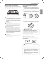
Anti-tip
bracket
Leveling
leg

5
IMPORTANT SAFETY INSTRUCTIONS
ENGLISH
•
Do not rest large, heavy items such as whole turkeys on the open oven door. The range
could tip forward and cause injury.
•
Reengage the anti-tip device after pulling the range out for cleaning, service, or any other
reason.
•
Failure to follow these instructions can result in death or serious burns to children or
adults.
IMPORTANT SAFETY NOTICE
Gas appliances can cause minor exposure to four of these substances, namely benzene,
carbon monoxide, formaldehyde and soot, caused primarily by the imperfect combustion
of natural or LP gas. Correctly adjusted burners, indicated by a bluish rather than a yellow
flame, will minimize imperfect combustion. Exposure to these substances can be minimized
by opening windows or using a ventilation fan or hood.
WARNING
•
Never use your range as a space heater to heat or warm the room. Doing so may result
in carbon monoxide poisoning and overheating of the oven.
•
Never wear loose fitting or hanging garments while using the appliance. Be careful
when reaching for items placed in cabinets over the range. Flammable materials could
be ignited if brought in contact with flame or hot oven surfaces and may cause severe
burns.
•
Do not place or use combustible materials such as gasoline or other flammable vapors
and liquids in the vicinity of this or any other appliance.
•
Do not place flammable materials in the oven or near the cooktop.
•
Do not allow cooking grease or other flammable materials in or near the range.
•
Do not use water on grease fires. Never touch a flaming pan. Turn the controls off.
Smother a flaming pan on a surface burner by covering the pan completely with a
well-fitting lid, cookie sheet or flat tray. Use a multi-purpose dry chemical or foam-type
fire extinguisher.
A grease fire can be put out by covering it with baking soda or, if available, by using a
multi-purpose dry chemical or foam-type fire extinguisher.
Flame in the oven or the drawer can be smothered completely by closing the oven door
or drawer and turning the control to off or by using a multi-purpose dry chemical or
foam-type fire extinguisher.
•
Do not use the oven for storage.
•
Let the burner grates and other surfaces cool before touching them.
•
Never block the vents (air holes) of the range. They provide the air inlet and outlet
necessary for the range to operate properly with correct combustion. Air openings are
located at the rear of the cooktop, at the top and bottom of the oven door, and at the
bottom of the range.
•
Never obstruct the flow of combustion and ventilation air by blocking the oven vent
or air intakes. Doing so restricts air to the burner and may result in carbon monoxide
poisoning.

6
IMPORTANT SAFETY INSTRUCTIONS
WARNING
•
Never cover any slots, holes or passages in the oven bottom or cover an entire rack
with materials such as aluminum foil. Doing so blocks air flow through the oven and
may cause carbon monoxide poisoning. Aluminum foil linings may also trap heat,
causing a fire hazard.
•
Large scratches or impacts to glass doors can lead to broken or shattered glass.
•
Stepping, leaning or sitting on the doors or drawers of this range can result in serious
injuries and also cause damage to the range. Do not allow children to climb or play
around the range. The weight of a child on an open door may cause the range to tip,
resulting in serious burns or other injury.
•
Leak testing of the appliance must be conducted according to the manufacturer’s
instructions.
•
Gas leaks may occur in the system and result in a serious hazard. Gas leaks may
not be detected by smell alone. Gas suppliers recommend you purchase and install
a UL approved gas detector. Install and use in accordance with the gas detector
manufacturer’s instructions.
•
Do not use commercial oven cleaners on the oven finish or around any part of the
oven. They will damage the finish.
•
To prevent staining or discoloration, clean appliance after each use.
•
Do not attempt to open or close the door or operate the oven until the door is properly
installed.
•
Never place fingers between the hinge and front oven frame. Hinge arms are spring
mounted. If accidentally hit, the hinge will slam shut against the oven frame and injure
your fingers.
CAUTION
•
Items of interest to children should not be placed in cabinets above the range or on
the backsplash of the range - children climbing on the range to reach items could be
seriously injured.
•
Do not leave children alone or unattended where a range is hot or in operation. They
could be seriously burned.
•
Do not let anyone climb, stand or hang on the oven door, warming drawer or cooktop.
They could damage the range or tip it over, causing severe personal injury.
•
Wear gloves when cleaning the range to avoid injury or burns.
•
Do not use the oven for storing food or cookware.
•
To prevent damage to the oven door, do not attempt to open the door when Lock is
displayed.
•
Do not stand or place excessive weight on an open door. This could tip the range,
break the door, or injure the user.
•
Do not use delayed baking for highly perishable foods such as dairy products, pork,
poultry, or seafood.

7
IMPORTANT SAFETY INSTRUCTIONS
ENGLISH
INSTALLATION SAFETY PRECAUTIONS
Have the installer show you the location of the range gas shut-off valve and how to shut it
off if necessary.
WARNING
•
Make sure your range is properly installed and grounded by a qualified installer,
according to the installation instructions. Any adjustment and service should be
performed only by qualified gas range installers or service technicians.
•
Make sure your range is properly adjusted by a qualified service technician or installer
for the type of gas (natural or LP) that is to be used. Your range can be converted for
use with either type of gas. See the installation instructions.
•
These adjustments must be done by a qualified service technician according to the
manufacturer’s instructions and all codes and requirements of the authority having
jurisdiction. Failure to follow these instructions could result in serious injury or property
damage. The qualified agency performing these adjustments assumes responsibility for
the conversion.
•
Disconnect the electrical supply before servicing the appliance.
•
Never use the appliance door as a step stool or seat, as this may result in possible
tipping of the appliance and serious injuries.
•
This product should not be installed below ventilation type hood systems that direct air
in a downward direction.
Doing so may cause ignition and combustion problems with the gas burners resulting in
personal injury and may affect the cooking performance of the unit.
•
Plug your range into a 120-volt grounded outlet only. Do not remove the round
grounding prong from the plug. If in doubt about the grounding of the home electrical
system, it is your personal responsibility and obligation to have an ungrounded outlet
replaced with a properly grounded, three-prong outlet in accordance with the National
Electrical Code. Do not use an extension cord with this range.
•
To prevent fire hazard or electrical shock, do not use an adapter plug, an extension
cord, or remove the grounding prong from the electrical power cord. Failure to follow
this warning can cause serious injury, fire or death.
•
To prevent poor air circulation, place the range out of the kitchen traffic path and out of
drafty locations.
•
Do not attempt to repair or replace any part of your range unless it is specifically
mentioned in this manual. All other services should be referred to a qualified technician.
•
Make sure that all packaging materials are removed from the range before operating it
to prevent fire or smoke damage should the packaging material ignite.

8
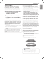
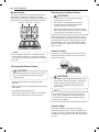
IMPORTANT SAFETY INSTRUCTIONS
WARNING
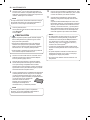
•
To shut off the gas supply to the range, close the range gas shutoff valve by turning it
clockwise.
1
/
2
"
Adapter
1
/
2
"
Adapter
Range gas shutoff valve
Gas Flow into Range
Installer: Inform the consumer of the location of the gas shut-off valve.
•
After using your range for an extended period of time high floor temperatures may
result. Many floor coverings will not withstand this kind of use.
•
Never install the range over vinyl tile or linoleum that cannot withstand such type of
use. Never install it directly over interior kitchen carpeting.
SURFACE BURNERS
WARNING
•
Even if the top burner flame goes out, gas is still flowing to the burner until the knob is
turned to the Off position. If you smell gas, immediately open a window and ventilate
the area for five minutes prior to using the burner. Do not leave the burners on
unattended.
•
Use proper pan size. Do not use pans that are unstable or that can be easily tipped.
Select cookware with flat bottoms large enough to cover burner grates. To avoid
spillovers, make sure the cookware is large enough to contain the food properly. This
will both save cleaning time and prevent hazardous accumulations of food, since heavy
spattering or spillovers left on the range can ignite. Use pans with handles that can be
easily grasped and remain cool.

9
IMPORTANT SAFETY INSTRUCTIONS
ENGLISH
CAUTION
•
Be sure that all surface controls are set in the Off position prior to supplying gas to the
range.
•
Never leave the surface burners unattended at high flame settings. Boilovers may
cause smoke and greasy spillovers that may ignite.
•
Always turn the knobs to the Lite position when igniting the top burners and make sure
the burners have ignited.
•
Control the top burner flame size so it does not extend beyond the edge of the
cookware. Excessive flame is hazardous.
•
Only use dry pot holders- moist or damp pot holders on hot surfaces may result in
burns from steam. Do not let pot holders come near open flames when lifting cookware.
Do not use towels or other bulky cloth items. Use a pot holder.
•
If using glass cookware, make sure the cookware is designed for range-top cooking.
•
To prevent burns from ignition of flammable materials and spillage, turn cookware
handles toward the side or back of the range without extending them over adjacent
burners.
•
Never leave any items on the cooktop. The hot air from the vent may ignite flammable
items and will increase pressure in closed containers, which may cause them to burst.
•
Carefully watch foods being fried at a high flame setting.
•
Always heat fat slowly, and watch as it heats.
•
If frying combinations of oils and fats, stir together before heating.
•
Use a deep fat thermometer if possible to prevent overheating fat from heating beyond
the smoking point.
•
Use the least possible amount of fat for effective shallow or deep fat frying. Filling the
pan with too much fat can cause spillovers when food is added.
•
Do not cook foods directly on an open flame on the cooktop.
•
Do not use a wok on the surface burners if the wok has a round metal ring that is
placed over the burner grate to support the wok. This ring acts as a heat trap, which
may damage the burner grate and burner head. It may also cause the burner to work
improperly. This may cause carbon monoxide levels which are higher than what is
allowed by current standards, resulting in a health hazard.
•
Foods for frying should be as dry as possible. Frost or moisture on foods can cause hot
fat to bubble up and spill over the sides of the pan.
•
Never try to move a pan of hot fat, especially a deep fryer. Wait until the fat is cool.
•
Do not place plastic items on the cooktop- they may melt if left too close to the vent.
•
Keep all plastics away from the surface burners.
•
To prevent burns, always be sure that the controls for all burners are in the Off position
and all grates are cool before attempting to remove them.
•
If you smell gas, turn off the gas to the range and call a qualified service technician.
Never use an open flame to locate a leak.
•
Always turn the knobs to the Off position before removing cookware.
•
Do not lift the cooktop. Lifting the cooktop can cause damage and improper operation
of the range.
•
If the range is located near a window, do not hang long curtains that could blow over
the surface burners and catch on fire.
•
Use care when cleaning the cooktop. The pointed metal ends on the electrodes could
cause injury.

10
IMPORTANT SAFETY INSTRUCTIONS
BROILER
Always use a broiler pan and a grid for excess fat and grease drainage. This will help to
reduce splatter, smoke, and flare-ups.
WARNING
When using your broiler, the temperature inside the oven will be extremely high. Take
caution to avoid possible burns by:
•
Keeping the door closed when broiling (refer to Broil section of the manual)
•
Always wearing oven mitts when inserting or removing food items
COOK MEAT AND POULTRY THOROUGHLY
To protect against food-borne illnesses, cook meat and poultry thoroughly—meat to at least
an INTERNAL temperature of 160 °F, poultry to at least an INTERNAL temperature of 165 °F
and beef, pork, veal & lamb steaks & chops to at least an INTERNAL temperature of 145 °F.
SELF-CLEANING OVEN
Make sure to wipe off excess spillage before operating the Self Clean function.
CAUTION
•
Do not leave food, broiler trays, cooking utensils, racks, etc. in the oven during the self
clean cycle.
•
Do not use oven cleaners. No commercial oven cleaner or oven liner protective coating
of any kind should be used in or around any part of the oven. Residue from oven
cleaners will damage the inside of the oven when the self clean cycle is used.
•
Remove oven racks and other items from oven before starting the self clean cycle.
•
Only clean the parts listed in this manual.
•
Do not manually clean the door gasket. The door gasket is necessary for a good seal.
Care should be taken not to rub, damage or move the gasket.
•
If the self cleaning mode malfunctions, turn the range off and disconnect the power
supply. Have it serviced by a qualified technician.
•
It is normal for parts of the oven to become hot during a Self Clean cycle.
•
Avoid touching the door, window or oven vent area during a Self Clean cycle.
OVEN
When opening the door of a hot oven, stand away from the range. The hot air and steam
that escape can cause burns to hands, face and eyes.
WARNING
•
Never block any slots, holes or passages in the oven bottom or cover an entire rack
with materials such as aluminum foil. Doing so blocks air flow through the oven and
may cause carbon monoxide poisoning. Aluminum foil linings may trap heat, causing a
fire hazard.
•
Do not heat food in closed containers. Pressure inside the container could increase and
cause the container to burst, resulting in injury.

11
IMPORTANT SAFETY INSTRUCTIONS
ENGLISH
WARNING
•
Do not line oven walls or bottom with aluminum foil or allow them to contact exposed
heating elements in the oven. Doing so could create a fire hazard or cause damage to
the range.
•
Do not use the oven for storage. Items stored in the oven can catch on fire.
•
Keep the oven free from grease buildup.
•
Insert the oven racks in the desired position while the oven is cool.
•
To prevent burns when removing food, slide racks out until the stop engages, then
remove food items. This may also protect you from getting burnt by touching hot
surfaces of the door or oven walls.
•
When placing or removing a griddle, always wear oven mitts.
•
When using cooking or roasting bags in the oven, follow the manufacturer’s directions.
•
Use only glass cookware that is recommended for use in gas ovens.
•
Always remove the broiler pan from the range after you finish broiling. Grease left in the
pan can catch fire if the oven is used without removing the grease from the broiler pan.
•
If meat is too close to the flame while broiling, the fat may ignite. Trim excess fat to
prevent excessive flare-ups.
•
Make sure the broiler pan is in place correctly to minimize the possibility of grease fires.
•
If you have a grease fire in the broiler pan, turn the oven mode knob to the Off position
and keep the oven door closed to contain the fire until it burns out.
•
For safety and better cooking performance, always bake and broil with the oven door
closed. Open door baking or broiling can cause damage to the knobs or valves.
Do not leave the oven door open during cooking or while the oven is cooling down.
ENERGY SAVING TIPS
•
Multiple-rack cooking saves time and energy. Whenever possible, cook foods requiring the
same cooking temperature together in one oven.
•
For optimal performance and energy savings, follow the guides on page 36 for proper rack
and pan placements.
•
Match the size of the cookware to the amount of food being cooked to save energy when
heating. Heating ½ quart of water requires more energy in a 3-quart pot than in a 1-quart
pot.
•
Use cookware with flat bottoms to provide the best contact with the cooktop surface when
cooking on the glass-ceramic cooktop.
•
Match the size of the cooktop burner or element to the size of the cookware in use. Using
a large element for a small pan wastes heating energy, and the exposed surface of the
element is a burn or fire hazard.
•
Reduce energy use by cleaning light oven soils with the EasyClean
®
feature instead of
self-clean.
•
Avoid opening the oven door more than necessary during use. This helps the oven
maintain temperature, prevents unnecessary heat loss, and saves on energy use.
Read all instructions before using the appliance.
SAVE THESE INSTRUCTIONS

12
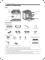
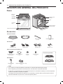
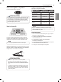
PRODUCT OVERVIEW
PRODUCT OVERVIEW
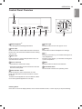
Parts
Gasket
Oven mode knob
Model & serial
number plate
Storage drawer
Cooktop
controller
Oven door
Cooktop
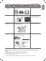
Accessories
Included Accessories
Standard rack (3ea) Griddle (1ea) Rear ller (1ea) Owner’s manual (1ea)
Anti-tip kit
Anti-tip (1ea) Screws (6ea) Anchors (6ea) Template (1ea)
LP nozzle conversion kit
Optional Accessories
Broiler pan
Grid
Cooktop Nozzles
(5ea)
Installation Guide
(1ea)
Choke
(1ea)
Set screw
(1ea)
EasyClean™ kit
Spray bottle (1ea) Non-scratch scouring pad (1ea)
NOTE
•
Contact LG Customer Service at 1-800-243-0000 if any accessories are missing.
•
For your safety and for extended product life, only use authorized components.
•
The manufacturer is not responsible for product malfunction or accidents caused by the use of separately
purchased, unauthorized components or parts.
•
The images in this guide may be different from the actual components and accessories, which are subject
to change by the manufacturer without prior notice for product improvement purposes.

13
INSTALLATION
ENGLISH
INSTALLATION
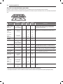
Product Specifications
The appearance and specifications listed in this manual may vary due to constant product improvements.
Oven Range Models LSD4913
Description Dual Fuel Range
Electrical requirements 4.2 kW 120/240 VAC or 3.2 kW 120/208 VAC
Exterior Dimensions
29
7
/
8
" (W) x 37
7
/
8
" (H) x 26
1
/
2
" (D) (D with door closed)
75.7 cm (W) x 96 cm (H) x 67.3 cm (D) (D with door closed)
Height to cooking surface 36" (91.4 cm)
Net weight 181 lb (82.0 kg)
Total capacity Total cap.: 6.3 cu. ft.
Before Installing the Range
Make sure your range is properly installed and grounded by a qualified installer, according to the installation
instructions. Any adjustment and service should be performed only by qualified gas range installers or service
technicians.
In the Commonwealth of Massachusetts
•
This product must be installed by a licensed plumber or gas fitter.
•
When using ball type gas shut-off valves, they must be the T-handle type.
•
When using a flexible gas connector, it must not exceed 3 feet in length.
Preparing for Installation
Tools Needed
Phillips screwdriver
Open-end or adjustable
wrench
Pencil and ruler
Level
Flat-blade screwdriver
Pipe wrench (2)
(one for support)
Materials You May Need
•
Gas line shut-off valve
•
Pipe joint sealant that resists action of natural and LP gases
•
Flexible metal appliance connector (
3
/
4
" or
1
/
2
" NPT x
1
/
2
" I.D.)
Never use an old connector when installing a new range.
•
Flare union adapter for connection to gas supply line (
3
/
4
" or
1
/
2
" NPT x
1
/
2
" I.D.)
•
Flare union adapter for connection to pressure regulator on range (
1
/
2
" NPT x
1
/
2
" I.D.)
•
Liquid leak detector or soapy water
•
Lag bolt or
1
/
2
" O.D. sleeve anchor (for concrete floors only)

14
INSTALLATION
Installing the Range
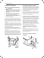
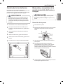
Unpacking and Moving the Range
CAUTION
•
You should use two or more people to move
and install the range. (Excessive Weight
Hazard) Failure to do so can result in back or
other injury.
•
Do not use the door handles to push or
pull the range during installation or when
moving the range out for cleaning or
service. Doing so can result in serious damage
to the door of the range.
Remove packing material, tape and any temporary
labels from your range before using. Do not remove
any warning-type labels, the model and serial number
label, or the Tech Sheet that is located on the back of
the range.
To remove any remaining tape or glue, rub the area
briskly with your thumb. Tape or glue residue can also
be easily removed by rubbing a small amount of liquid
dish soap over the adhesive with your fingers. Wipe
with warm water and dry.
Do not use sharp instruments, rubbing alcohol,
flammable fluids, or abrasive cleaners to remove tape
or glue. These products can damage the surface of
your range.
Your range is heavy and can be installed on soft
floor coverings such as cushioned vinyl or carpeting.
Use care when moving the range on this type of
flooring. Use a belt when moving the range to prevent
damaging the floor. Or slide the range onto cardboard
or plywood to avoid damaging the floor covering.
Choosing the Proper Location
Do not locate your range where it may be subject to
strong drafts. Any openings in the floor or wall behind
the range should be sealed. Make sure the openings
around the base of the range that supply fresh air
for combustion and ventilation are not blocked by
carpeting or woodwork.
Your range, like many other household units, is heavy
and can be installed on soft floor coverings such as
cushioned vinyl or carpeting. Use care when moving
the range on this type of flooring.
This appliance must not be installed with a ventilation
system that blows air downward toward the range.
This type of ventilation system may cause ignition and
combustion problems with the gas cooking appliance
resulting in personal injury or unintended operation.
When the floor covering ends at the front of the
range, the area that the range will be installed on
should be built up with plywood to the same level
or higher than the floor covering. This will allow the
range to be moved for cleaning and servicing, as well
as provide proper air flow to the range.
Also, make sure the floor covering can resist
temperatures of at least 167 °F (75 °C). See the
Installation Safety Instructions included in this
manual.
Make sure the wall coverings around your range
can resist the heat generated up to 194 °F (90 °C)
by the range. See the Installation Safety Instructions
included in this manual.
Gas Pipe and Electrical Outlet
Locations
30"
(76.2 cm)
7
14
/
16
"
(20 cm)
11
13
/
16
"
(30 cm)
3
6
/
16
"
(8.5 cm)
3"
(7.6 cm)
17
15
/
16
"
(45.6 cm)
5
14
/
16
"
(15 cm)
6
11
/
16
"
(17 cm)

15
INSTALLATION
ENGLISH
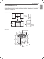
Dimensions and Clearances
Provide proper clearance between the range and adjacent combustible surfaces. These dimensions must be met
for safe use of your range. The location of the electrical outlet and pipe opening (see Gas Pipe and Electrical
Outlet Locations, page 14) may be adjusted to meet specific requirements. The range may be placed with 0"
clearance (flush) at the back wall.
Installation Clearances
30"
(76.2 cm)
30" (76.2 cm)
Minimum
15"
(38.1 cm)
36"
(91.4 cm)
13"
(33.0 cm)
Maximum
depth for
cabinets above
coutertops
Front edge of
the range side
panel forward
from cabinet
0"
To cabinets
below
cooktop and
at the range
back
1
/
4
"
Dimensions
28
3
/
4
"
(73.0 cm)
Height
37
59
/
64
"
(96.3 cm)
Depth with door open
43
5
/
32
" (109.6 cm)
Depth with door closed
(includes door handle)
36"
(91.4 cm)
29
7
/
8
"
(75.7 cm)

16
INSTALLATION
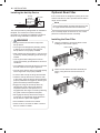
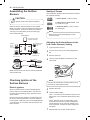
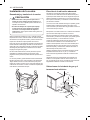
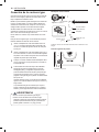
Installing the Anti-tip Device
Anti-tip
bracket
Wall plate
Screw must
enter wood or
concrete
The anti-tip bracket is packaged with an installation
template. The instructions include necessary
information to complete the installation. Read and
follow the range installation instruction sheet.
WARNING
•
Range must be secured with an approved
anti-tip device.
•
The range could be tipped by standing, sitting
or leaning on an open door if the range or
anti-tip device is not properly installed.
•
After installing the anti-tip device, verify that it is
in place by carefully attempting to tilt the range
forward.
•
This range has been designed to meet all
recognized industry tip standards for all normal
conditions.
•
The installation of the anti-tip device must meet
all local codes for securing the appliance.
•
The use of this device does not preclude tipping
of the range when not properly installed.
•
A child or adult can tip the range and be killed.
•
Install the anti-tip device to the structure and/
or the range. Verify the anti-tip device has been
properly installed and engaged by following the
guide of the Anti tip bracket template.
•
Engage the range to the anti-tip device by
following the guide of the Anti tip bracket
template. Ensure the anti-tip device is re-
engaged when the range is moved by following
the guide of the Anti tip bracket template.
•
Re-engage the anti-tip device if the range is
moved. Do not operate the range without the
anti-tip device in place and engaged.
•
See installation instructions for details.
•
Failure to do so can result in death or serious
burns to children or adults.
Optional Rear Filler
If the counter does not bridge the opening at the rear
wall the rear filler kit, that is provided with the slide in
range, will be needed.
NOTE
If the countertop depth is greater than 25" there will
be a gap between the filler kit and the back wall.
If the countertop depth is less than 24", the control
panel will not sit flush with the countertop.
Installing the Rear Filler
1
Using a screwdriver, remove the three screws
holding the rear bracket in place.
Rear bracket
2
Attach the rear bracket and filler assembly as
shown, using the three screws removed in
step 1.
Rear ller

17
INSTALLATION
ENGLISH
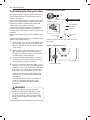
Providing Adequate Gas
Supply
Your range is designed to operate at a pressure of
5" of water column on natural gas or 10" of water
column on LP.
Make sure you are supplying your range with the type
of gas for which it is configured.
This range is convertible for use on natural or LP gas.
When using this range on LP gas, conversion must
be made by a qualified LP installer before attempting
to operate the range.
For proper operation, the pressure of natural gas
supplied to the regulator must be between 5" and 13"
of water column.
For LP gas, the pressure supplied to the regulator
must be between 10" and 13" of water column. When
checking for correct operation of the regulator, the
inlet pressure must be at least 1" more than the
operating (manifold) pressure as given above.
The pressure regulator located at the inlet of the
range must remain in the supply line regardless of
which type of gas is being used.
A flexible metal appliance connector used to connect
the range to the gas supply line should have an I.D.
of
5
/
8
" and a maximum length of 5 feet.

18
INSTALLATION
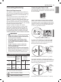
Connecting the Range to Gas
Shut off the range gas supply valve before removing
the old range and leave it off until the new hook-up
has been completed.
Because hard piping restricts movement of the range,
the use of a CSA International-certified flexible metal
appliance connector should be used unless local
codes require a hard-piped connection.
A manual valve shall be installed in an accessible
location in the gas piping external to the appliance
for the purpose of turning on or shutting off gas to the
appliance.
Never reuse an old connector when installing a new
range.
To protect against gas leaks, use a qualified pipe joint
sealant on all external threads.
1
Install a male
1
/
2
" or
3
/
4
" flare union adapter to the
NPT internal thread of the manual shut-off valve,
taking care to back-up the shut-off valve to keep
it from turning.
2
Install a male
1
/
2
" flare union adapter to the
1
/
2
"
NPT internal thread at the inlet of the pressure
regulator. Use a backup wrench on the pressure
regulator fitting to prevent damage.
3
Connect a flexible metal appliance connector to
the adapter on the range. Position the range to
permit connection at the shut-off valve.
4
When all connections have been made, be sure
all range controls are in the OFF position before
turning on
the main gas supply valve. Gas leaks
may occur in
your system and create a hazard.
Gas leaks may not
be detected by smell alone.
Check all gas connection joints and fittings for
leaks with a non-corrosive leak detection fluid,
then wipe off.
Gas suppliers recommend you purchase and
install a UL approved gas detector. Install
and use in accordance with the installation
instructions.
WARNING
•
Do not use a flame to check for gas leaks.
•
Isolate the range from the gas supply system
by closing its individual shut-off valve during
any pressure testing of the gas supply system
at test pressures equal to or less than
1
/
2
" psig
(3.5 kPa).
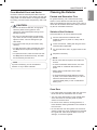
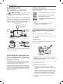
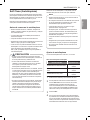
Flexible Connector Hookup
1
/
2
"
Adapter
1
/
2
"
Adapter
Pressure regulator
Flex connector
(6 ft. max.)
Adapter
Gas shut-off
valve
1
/
2
" or
3
/
4
" Gas
pipe
Gas Flow into Range
Installer: Inform the consumer of the location of the gas
shut-off valve
.
Pressure Regulator Position
Pressure Regulator

19
INSTALLATION
ENGLISH
Connecting Electricity
Electrical Requirements
This appliance must be installed and grounded on a
branch circuit by a qualified technician in accordance
with the National Electrical code ANSI/NFPA NO. 70 -
latest edition.
All wiring should conform to Local and NEC codes.
This range requires a single-phase, 3 wire, A.C
120/208 V or 120/240 V 60 Hz electrical system. Use
only a 3-conductor or a 4-conductor UL- listed range
cord with closed-loop terminals, open-end spade lugs
with upturned ends or similar termination. Do not install
the power cord without a strain relief.
A range cord rated at 40 amps with 120/240
minimum volt range is required. If a 50 amp range
cord is used, it should be marked for use with 1
3
/
8
"
diameter connection openings. This appliance may
be connected by means of a conduit or power cord.
If a conduit is being used, go to page 21 for 3 wire
conduit connections or 4 wire conduit connections.
WARNING
•
Allow 2 to 3 ft (61.0 cm to 91.4 cm) of slack
in the line so that the range can be moved if
servicing is ever necessary.
•
The power supply cord and plug should
not be modified. If it will not fit the outlet,
have a proper outlet Installed by a qualified
electrician.
•
Using an extension cord to connect the
power is prohibited. Connect the power
cord and plug directly.
•
Electrical ground is required on this appliance.
•
Make sure that the power cord is not pinched
by the range or heavy objects. Failure to do so
can result in serious burns or electrical shock.
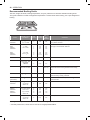
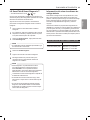
Specified power-supply-cord kit rating
Range rating, watts
Specified
rating of
power
supply-
cord kit,
amperes
Diameter (inches)
of Range
connection
Opening
120/240
volts
3-wire
120/208
volts
3-wire
Power
cord
Conduit
8,750 -
16,500
16,501 -
22,500
7,801 -
12,500
12,501 -
18,500
40 or 50A
50
1
3
/
8
"
1
3
/
4
"
1
1
/
8
"
1
3
/
8
"
3, 4 - Wire electrical wall Receptacle
4 Wire receptacle (14-50R)
3 Wire receptacle (10-50R)
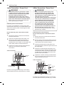
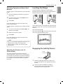
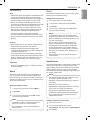
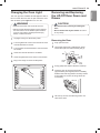
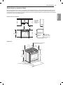
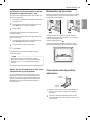
Connecting the Power Cord
The rear access cover must be removed. Loosen the
two screws with a screwdriver. The terminal block will
then be accessible.
Access cover
Use the cord/conduit connection plate to install the
power cord or conduit. Leave the connection plate
as installed for power cord installations. Remove the
connection plate for conduit installations and use the
smaller 1
1
/
8
in. (2.8 cm) conduit hole instead of the
1
3
/
8
in. (3.5 cm) power cord hole.
Remove the conduit connection plate
1
1
/
8
"
(2.8 cm) Conduit
1
3
/
8
"
(3.5 cm) Cord
For power cord installations, hook the strain relief
over the 1
3
/
8
in. (3.5 cm) power cord hole located
below the rear of the oven. Insert the power cord
through the strain relief and tighten it.
Conduit
connection
plate
Power cord
Assembling power cord strain relief at the 1
3
/
8
" opening
For conduit installations, insert the conduit strain
relief in the 1
1
/
8
in. (2.8 cm) conduit hole. Then install
the conduit through the body of the strain relief and
fasten the strain relief with its ring.
Cord/
Conduit
connection
plate
Conduit
Ring
Body
Assembling conduit cord strain relief at the 1
1
/
8
" opening

20
INSTALLATION
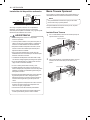
3-Wire Connection : Power Cord
WARNING
•
The middle (neutral or ground) wire, which
is white, of a 3-wire power cord or a 3-wire
conduit has to be connected to the middle
post of the main terminal block. The
remaining two wires of the power cord or
conduit have to be connected to the outside
posts of the main terminal connection block.
Failure to do so can result in electrical shock,
severe personal injury or death.
Install the power cord as follows:
For power cord installations, hook the strain relief
over the power cord hole (1
3
/
8
"
) located below the rear
of the oven. Insert the power cord through the strain
relief and tighten it.
Do not install the power cord without a strain
relief.
1
Remove the lower 3 screws from the terminal
block and retain them.
2
Insert the 3 screws through each power cord
terminal ring and into the lower terminals of
the terminal block. Make sure that the center
(neutral) wire, which is white, is connected to the
center lower position of the terminal block.
3
Tighten the 3 screws securely into the terminal
block. Do not remove the ground strap
connections.
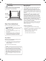
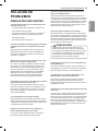
3-wire connection
Black White Red
Terminal
block
Conduit
connection plate
If screws are not tightened securely, it can result in
electrical spark and severe personal injury or death.
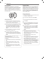
4-Wire Connection : Power Cord
WARNING
•
Only a 4-conductor power-supply cord
kit rated 120/240 volts, 50 amperes and
marked for use with ranges with closed-
loop connectors or opened spade lugs with
upturned ends shall be used.
The white middle (neutral) wire of the power
cord or 4-wire conduit has to be connected
to the middle post of the main terminal
block. The other two wires of the power
cord or conduit have to be connected to
the outside posts of the main terminal
connection block. The 4th ground wire
(green) must be connected to the frame of
the range with the ground screw. Failure
to do so can result in electrical shock, severe
personal injury or death.
Install the power cord as follows:
Do not install the power cord without a strain
relief.
1
Remove the lower 3 screws from the terminal
block and retain them.
2
Remove the ground screw and bend the end of
the ground strap up so the slot is over the hole
of the center screw removed in step 1.
3
Insert the ground screw into the power cord
ground wire (green) terminal ring and secure it to
the range frame.
4
Insert the 3 screws through each power cord
terminal ring and into the lower terminals of the
terminal block. Make sure that the white center
(neutral) wire is connected to the center lower
position of the terminal block.
5
Tighten the 3 screws securely into the terminal
block. The center screw now attaches the bent
up ground strap to the block.
4-wire connection
Ground
strap
Terminal
block
Conduit
connection plate
Ground
screw
Black White Red
Bend strap up
and attach
If screws are not tightened securely, it can result in
electrical spark and severe personal injury or death.
Page is loading ...
Page is loading ...
Page is loading ...
Page is loading ...
Page is loading ...
Page is loading ...
Page is loading ...
Page is loading ...
Page is loading ...
Page is loading ...
Page is loading ...
Page is loading ...
Page is loading ...
Page is loading ...
Page is loading ...
Page is loading ...
Page is loading ...
Page is loading ...
Page is loading ...
Page is loading ...
Page is loading ...
Page is loading ...
Page is loading ...
Page is loading ...
Page is loading ...
Page is loading ...
Page is loading ...
Page is loading ...
Page is loading ...
Page is loading ...
Page is loading ...
Page is loading ...
Page is loading ...
Page is loading ...
Page is loading ...
Page is loading ...
Page is loading ...
Page is loading ...
Page is loading ...
Page is loading ...
Page is loading ...
Page is loading ...
Page is loading ...
Page is loading ...
Page is loading ...
Page is loading ...
Page is loading ...
Page is loading ...
Page is loading ...
Page is loading ...
Page is loading ...
Page is loading ...
Page is loading ...
Page is loading ...
Page is loading ...
Page is loading ...
Page is loading ...
Page is loading ...
Page is loading ...
Page is loading ...
Page is loading ...
Page is loading ...
Page is loading ...
Page is loading ...
Page is loading ...
Page is loading ...
Page is loading ...
Page is loading ...
Page is loading ...
Page is loading ...
Page is loading ...
Page is loading ...
Page is loading ...
Page is loading ...
Page is loading ...
Page is loading ...
Page is loading ...
Page is loading ...
Page is loading ...
Page is loading ...
Page is loading ...
Page is loading ...
Page is loading ...
Page is loading ...
Page is loading ...
Page is loading ...
Page is loading ...
Page is loading ...
Page is loading ...
Page is loading ...
Page is loading ...
Page is loading ...
Page is loading ...
Page is loading ...
Page is loading ...
Page is loading ...
Page is loading ...
Page is loading ...
Page is loading ...
Page is loading ...
Page is loading ...
Page is loading ...
Page is loading ...
Page is loading ...
Page is loading ...
Page is loading ...
Page is loading ...
Page is loading ...
Page is loading ...
Page is loading ...
Page is loading ...
Page is loading ...
-
 1
1
-
 2
2
-
 3
3
-
 4
4
-
 5
5
-
 6
6
-
 7
7
-
 8
8
-
 9
9
-
 10
10
-
 11
11
-
 12
12
-
 13
13
-
 14
14
-
 15
15
-
 16
16
-
 17
17
-
 18
18
-
 19
19
-
 20
20
-
 21
21
-
 22
22
-
 23
23
-
 24
24
-
 25
25
-
 26
26
-
 27
27
-
 28
28
-
 29
29
-
 30
30
-
 31
31
-
 32
32
-
 33
33
-
 34
34
-
 35
35
-
 36
36
-
 37
37
-
 38
38
-
 39
39
-
 40
40
-
 41
41
-
 42
42
-
 43
43
-
 44
44
-
 45
45
-
 46
46
-
 47
47
-
 48
48
-
 49
49
-
 50
50
-
 51
51
-
 52
52
-
 53
53
-
 54
54
-
 55
55
-
 56
56
-
 57
57
-
 58
58
-
 59
59
-
 60
60
-
 61
61
-
 62
62
-
 63
63
-
 64
64
-
 65
65
-
 66
66
-
 67
67
-
 68
68
-
 69
69
-
 70
70
-
 71
71
-
 72
72
-
 73
73
-
 74
74
-
 75
75
-
 76
76
-
 77
77
-
 78
78
-
 79
79
-
 80
80
-
 81
81
-
 82
82
-
 83
83
-
 84
84
-
 85
85
-
 86
86
-
 87
87
-
 88
88
-
 89
89
-
 90
90
-
 91
91
-
 92
92
-
 93
93
-
 94
94
-
 95
95
-
 96
96
-
 97
97
-
 98
98
-
 99
99
-
 100
100
-
 101
101
-
 102
102
-
 103
103
-
 104
104
-
 105
105
-
 106
106
-
 107
107
-
 108
108
-
 109
109
-
 110
110
-
 111
111
-
 112
112
-
 113
113
-
 114
114
-
 115
115
-
 116
116
-
 117
117
-
 118
118
-
 119
119
-
 120
120
-
 121
121
-
 122
122
-
 123
123
-
 124
124
-
 125
125
-
 126
126
-
 127
127
-
 128
128
-
 129
129
-
 130
130
-
 131
131
-
 132
132


Ask a question and I''ll find the answer in the document
Finding information in a document is now easier with AI
in other languages
Related papers
Other documents
-
LG STUDIO LSSG3017ST Owner's manual
-
LG SIGNATURE LUTG4519SN User manual
-
-
LG Electronics LTG4715ST User manual
-
Samsung NX58K7850S SERIES User manual
-
-
-
-
Yes NX60A6711SG User manual
-
Yes NX60A6511SS User manual