LG LSHD3089BD Owner's manual

Category
Cooker hoods
Type
Owner's manual
ENGLISH ESPAÑOL FRANÇAIS
INSTALLATION GUIDE
HOOD
Read these instructions thoroughly before installing and operating the hood.
www.lg.com
LSHD3689BD LSHD3089BD
LSHD3680ST LSHD3080ST
MFL70208702_02
Copyright © 2017 - 2019 LG Electronics Inc. All Rights Reserved.
2
TABLE OF CONTENTS
TABLE OF CONTENTS
3 BEFORE YOU BEGIN
4 IMPORTANT SAFETY
INSTRUCTIONS
7 PRODUCT SPECIFICATIONS
7 General Specifications
8 Dimensions
9 PRODUCT OVERVIEW
9 Parts
9 Accessories
10 PLANNING THE INSTALLATION
10 Cabinet Layout
11 Ducting Options
12 Ducting Calculation Sheet
13 Power Supply
13 Verify the Package Contents
14 INSTALLATION INSTRUCTIONS
14 Mounting the Range Hood
15 WIRING DIAGRAM
3
BEFORE YOU BEGIN
ENGLISH
BEFORE YOU BEGIN
IMPORTANT:
Installer: In the interest of safety and to minimize problems, read these installation
instructions completely and carefully before you begin the installation process. Leave
these installation instructions with the customer.
Customer: Keep these installation instructions for future reference and the local electrical
inspector’s use.
APPLIANCE DATA PLATE
The appliance data plate contains the model and serial number information and the
electrical requirements.
It is located inside the hood behind the filters on the back side of the chassis.
Remove the filters to view it.
All specifications subject to change without notice. LG STUDIO assumes no liability
for changes to specifications.
4
IMPORTANT SAFETY INSTRUCTIONS
Read and follow all instructions when using the range to prevent the risk of fire, electric
shock, personal injury, or damage. This guide does not cover all possible conditions that
may occur. Always contact your service agent or manufacturer about problems that you do
not understand.
Download this owner's manual at: http://www.lg.com
This is the safety alert symbol. This symbol alerts you to potential hazards that
can result in property damage and/or serious bodily harm or death.
All safety messages will follow the safety alert symbol and either the word
WARNING or CAUTION. These words mean:
WARNING
- Indicates a hazardous situation which, if not avoided, could result
in death or serious injury.
CAUTION
- Indicates a hazardous situation which, if not avoided, could result
in minor or moderate injury.
WARNING
To avoid the possibility of explosion or fire, do not store or use combustible, flammable
or explosive vapors and liquids (such as gasoline) inside or in the vicinity of this or
any other appliance. Also keep items that could explode, such as aerosol cans away
from cooktop burners, ovens and range hoods. Do not store flammable or explosive
materials in adjacent cabinets or areas.
If the information in this manual is not followed exactly, a fire or explosion may result
causing property damage, personal injury or death.
Do not use an additional speed control device with this unit.
To avoid motor bearing damage and noisy and/or unbalanced impellers, keep
drywall spray, construction dust, etc. off power unit.
Your ventilator motor has a thermal overload which will automatically shut off
the motor if it becomes overheated. The motor will restart when it cools down. If
the motor continues to shut off and restart, have the product serviced.
TO REDUCE THE RISK OF FIRE, ELECTRIC SHOCK, OR INJURY TO PERSONS,
OBSERVE THE FOLLOWING:
Use this unit only in the manner intended by the manufacturer. If you have questions,
contact the manufacturer.
Before servicing or cleaning unit, switch power off at service panel and lock the
electrical panel door to prevent power from being switched on accidentally. When the
electrical panel door cannot be locked, securely fasten a prominent warning device,
such as a tag, to the service panel.
5
IMPORTANT SAFETY INSTRUCTIONS
ENGLISH
WARNING
TO REDUCE THE RISK OF FIRE, ELECTRIC SHOCK, OR INJURY TO PERSONS,
OBSERVE THE FOLLOWING:
Installation work and electrical wiring must be done by qualified person(s) in
accordance with all applicable codes and standards, including fire-rated construction.
Sufficient air is needed for proper combustion and exhausting of gases through the
flue(chimney) of fuel burning equipment to prevent back drafting. Follow the heating
equipment manufacturer’s guidelines and safety standards such as those published
by the National Fire Protection Association (NFPA), and the American Society for
Heating, Refrigeration and Air Conditioning Engineers (ASHRAE), and the local code
authorities.
When cutting or drilling into wall or ceiling, do not damage electrical wiring and other
hidden utilities.
Ducted fans must always be vented to the outdoors.
CAUTION
For general ventilating use only. Do not use to exhaust hazardous or explosive materials
and vapors.
GENERAL SAFETY PRECAUTIONS
To reduce the risk of fire, electric shock, serious injury or death when using the appliance,
follow basic safety precautions, including the following:
WARNING
Do not install or operate this hood if it has been damaged, dropped, has damaged
electrical wires or is not working properly. If the product is damaged when received,
immediately contact the dealer or builder.
This range hood must be installed and grounded by a qualified installer according to
these installation instructions.
Install or locate this appliance only in accordance with these installation instructions
and the requirements specified by the manufacturer of the cooktop or range. Improper
installation, adjustment, alteration, service or maintenance can cause serious personal
injury or property damage.
The customer should not install, repair or replace any part of the range hood unless
specifically recommended in the literature accompanying it. A qualified service
technician should perform all other service.
Keep all packaging materials away from children. Plastic bags can cause suffocation.
Do not use an extension cord or adapter plug with this appliance.
The installer must show the customer the location of the fuse box or circuit breaker
panel box so that the customer knows where and how to turn the power off.
Before installing or servicing the range hood, switch power off at the fuse box circuit
breaker and lock the electrical panel door to prevent power from being switched on
accidentally. When the electrical panel cannot be locked, securely fasten a prominent
warning device, such as a tag, to the electrical panel.
Read the owner's manual completely before using the appliance. Clean the appliance
only as instructed in the owner's manual. Use only the cleaners specified.
Do not tamper with the controls.
6
IMPORTANT SAFETY INSTRUCTIONS
WARNING
Never allow the filter(s) to become blocked or clogged. Do not allow foreign objects,
such as cigarettes or napkins, to be sucked into the hood.
Clean the filter(s) and all grease-laden surfaces often to prevent grease fires and
maintain performance.
If the cooktop and range hood are near a window, use an appropriate window
treatment. Avoid long drapes or other window coverings that could blow over the
cooktop and hood, resulting in a fire hazard.
Always run the fan(s) whenever the cooktop is operating.
Never leave the range or cooktop unattended when a burner (or element) is in use.
Boil-overs and greasy spills may smoke and/or ignite.
Do not leave children alone or unattended in the area where the cooktop and range
hood are in use. Never allow children to sit or stand on an appliance. Do not let children
play with a range, cooktop or range hood. Do not store items of interest to children
above or around the cooktop, range or range hood.
The minimum vertical distance between the cooktop surface and the exterior part of
the hood must be no less than 26" (66 cm). The vertical distance required may be
longer for the range or cooktop being used. Consult the range or cooktop installation
instructions for the minimum and maximum vertical distance from the appliance being
used.
TO REDUCE THE RISK OF FIRE, USE ONLY METAL DUCT WORK.
READ AND SAVE THESE INSTRUCTIONS
7
PRODUCT SPECIFICATIONS
ENGLISH
PRODUCT SPECIFICATIONS
General Specifications
All Models
Fan Speeds 5
Filters Aluminum mesh filters
Total Connect Load 120 VAC, 60 Hz, 4 Amp.
Lights 120 VAC, 8 W LED light strip
Model Specic
Model Number LSHD3689BD, LSHD3680ST, LSHD3089BD, LSHD3080ST,
Filters 2
Weight Specications
Model Number Weight
LSHD3689BD, LSHD3680ST 37 lb. (17 kg)
LSHD3089BD, LSHD3080ST 35 lb. (16 kg)
8
PRODUCT SPECIFICATIONS
Dimensions
Tolerances: +1/16", -0 (1.6 mm, -0), unless otherwise stated.
NOTE
The exhaust duct(s) and electrical wiring can be connected from either the top or the back of the hood.
10
3/8
1
3/16
29 15/16″, 35 7/16
10
5/8
22
1/16
5 5/16
4"
1"
1"
6
"
STANDARD
min. ducted - 27″
min. recirc. - 31″
max. - 48″
18 7/16
Overall Dimensions
A
C
B
Model A B C
LSHD3689BD,
LSHD3680ST
36" 26
15
/
16
" 22
1
/
16
"
LSHD3089BD,
LSHD3080ST
30" 26
15
/
16
" 22
1
/
16
"
9
PRODUCT OVERVIEW
ENGLISH
PRODUCT OVERVIEW
Parts
1
4 5
23
Accessories
Included Accessories
Manual
Duct cover bracket Duct cover Manual M6 x 1" (3)
M6 x 1-1/2" (2) M4 x 8 (2) Wire Caps (3)
1
Hood
2
Icon Touch Control Panel
3
LED Strip Light
4
Mesh Filter
5
Side Panel
(Only for LSHD3689BD, LSHD3680ST)
10
PLANNING THE INSTALLATION
PLANNING THE
INSTALLATION
WARNING
Observe all governing codes and ordinances
during planning and installation. Contact your
local building department for further information.
Use only duct work deemed acceptable by state,
municipal and local codes.
Cabinet Layout
WARNING
To reduce the risk of personal injury caused by
reaching over a hot appliance, cabinet storage
space located directly above the range should be
avoided.
26″ min.
34
max.
minimum ducted (D)
minimum recirculating (E)
maximum (F)
36
minimum ducted (A)
minimum recirculating (B
)
maximum (C)
Minimum Cabinet Width
Standard
Duct Cover
Hood
Heights
minimum ducted (A) 27"
minimum recirculating (B) 31"
maximum (C) 48-1/2"
Ceiling
Heights
minimum ducted (D) 89" (7' 5")
minimum recirculating (E) 93" (7' 9")
maximum (F) 118" (9' 10")
Ducting
A minimum of 6″ round duct must be used to maintain
maximum air flow efficiency.
Always use rigid metal ducts only. Flexible ducts
could restrict air flow by up to 50%.
Also use calculation (on page 12) to compute total
available duct run when using elbows, transitions and
caps.
ALWAYS, when possible, reduce the number of
transitions and turns. If long duct run is required,
increase duct size from 6″ to 7″ or 8″.
If turns or transitions are required, install as far away
from hood duct output and as far apart as possible.
Minimum mount height between range top to hood
bottom should be no less than 26″.
Maximum mount height should be no higher than 34″.
It is important to install the hood at the proper
mounting height. Mounting the hood too low could
result in heat damage and fire hazard. Mounting the
hood too high will make it hard to reach and reduce
its performance and efficiency.
If available, also refer to the range manufacturer’s
height clearance requirements and recommended
hood mounting height above range.
CAUTION
DAMAGE DURING SHIPPING / INSTALLATION:
Please fully inspect unit for damage before
installation.
If the unit is damaged in shipment, return the
unit to the store in which it was bought for
repair or replacement.
If the unit is damaged by the customer, repair
or replacement is the responsibility of the
customer.
If the unit is damaged by the installer (if other
than the customer), repair or replacement must
be made by arrangement between customer
and installer.
11
PLANNING THE INSTALLATION
ENGLISH
Ducting Options
WARNING
Fire Hazard
NEVER exhaust air or terminate duct work into
spaces between walls, crawl spaces, ceiling,
attics or garages.
All exhaust must be ducted to the outside.
Use metal ductwork only.
Fasten all connections with sheet metal screws
and tape all joints with certified Silver Tape or
Duct Tape.
Sample Ducting Options
Roof Pitch w/
Flashing & Cap
(blower
housing)
ductless
recirculating
(blower
housing)
side wall cap
w/ gravity damper
Soft or crawl space
(blower
housing)
side wall cap
w/ gravity damper
(blower
housing)
12
PLANNING THE INSTALLATION
Ducting Calculation Sheet
Duct pieces
Equivalent
length x number
used =
Total
3-1/4" x 10"
Rect.,
straight
1 Ft. x ( ) = Ft.
6" Round,
straight
1 Ft. x ( ) = Ft.
7"-10"
Round,
straight
1 Ft. x ( ) = Ft.
3-1/4" x 10"
Rect.90˚
elbow
15 Ft. x ( ) = Ft.
3-1/4" x 10"
Rect.45˚
elbow
9 Ft. x ( ) = Ft.
3-1/4" x 10"
Rect.90˚
at elbow
24 Ft. x ( ) = Ft.
3-1/4" x 10"
Rect.
wall cap
with damper
30 Ft. x ( ) = Ft.
3-1/4" x 10"
Rect.to
6" round
transition
5 Ft. x ( ) = Ft.
3-1/4" x 10"
Rect.to
6" round
transition
90˚ elbow
20 Ft. x ( ) = Ft.
6" Round,
90˚ elbow
15 Ft. x ( ) = Ft.
6" Round,
45˚ elbow
9 Ft. x ( ) = Ft.
Subtotal column 1 = Ft.
Duct pieces
Equivalent
length x number
used =
Total
6" Round
wall cap
with damper
30 Ft. x ( ) = Ft.
6" Round,
roof cap
30 Ft. x ( ) = Ft.
6" round to
3-1/4" x 10"
rect.
transition
1 Ft. x ( ) = Ft.
6" round to
3-1/4" x 10"
rect.
transition
90˚ elbow
16 Ft. x ( ) = Ft.
7" - 10"
Round,
90˚ elbow
15 Ft. x ( ) = Ft.
7" - 10"
Round,
45˚ elbow
9 Ft. x ( ) = Ft.
7" - 10"
Round wall
cap with
damper
30 Ft. x ( ) = Ft.
7" - 10"
Round,
roof cap
30 Ft. x ( ) = Ft.
7" round to
3-1/4" x 10"
rect.
transition
8 Ft. x ( ) = Ft.
7" round to
3-1/4" x 10"
rect.
transition
90˚ elbow
23 Ft. x ( ) = Ft.
Subtotal column 2 = Ft.
Subtotal column 1 = Ft.
Total ductwork = Ft.
Maximum Duct Length: For satisfactory air
movement, the total duct length should not exceed
100 equivalent feet.
13
PLANNING THE INSTALLATION
ENGLISH
Ductwork Design Tips
Wherever possible, reduce the number of transitions
and turns to as few sharp angles as possible. Two
staggered 45° angles are better than one 90°.
Keep turns as far away from the hood exhaust as
possible, and allow as much space between bends
as possible.
For best performance, use round ducts instead of
rectangular, especially when elbows are required.
If multiple elbows are used, try to keep a minimum of
24" of straight duct between them.
Avoid “S” or “back to back” use of adjacent elbows.
In regions where the weather gets extremely cold,
use thermal breaks, such as a short section of non-
metallic duct, to avoid indoor heat loss. Locate the
break as close as possible to the outside pass-
through point.
Do not use flexible metal duct.
Do not use ductwork that is smaller in cross-sectional
area than the recommended types above.
Power Supply
WARNING
The information in this manual should be
followed exactly. Failure to do so could result
in fire or electrical shock, causing property
damage, personal injury or death.
All electrical work must by performed by
qualified electrician or person with similar
technical knowledge and background.
For personal safety, remove house fuse or open
circuit breaker before beginning installation. Do
not use extension cord or adapter plug with this
appliance.
Follow national electrical codes or
prevailing local codes and ordinances.
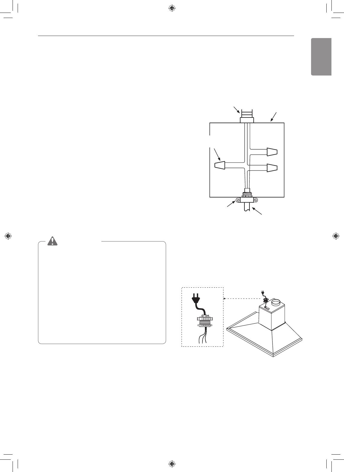
Electrical Supply
This appliance requires a 120V 60Hz electrical
supply, and must be connected to an individual,
properly grounded branch circuit, protected by a 15 or
20 ampere circuit breaker or time delay fuse. Wiring
must be 2 wire w/ ground. Please also refer to the
Electrical Diagram label on product.
GREEN
WHITE
WHITE
BLACK
BLACK
GREEN
Wire cap,
3 places
Junction box
To house circuit breaker
panel or fuse box
UL/CSA approved
NEMA strain relief
To range hood
3 Wire Connection to Junction Box
Cable Lock
A cable locking connector (not supplied) might
also be required by local codes. Check with local
requirements and codes, and purchase and install
appropriate connector if necessary.
Cable Lock
Verify the Package Contents
Unpack the parts box and verify that all parts and
accessories have been included. If any item is
missing or damaged, please contact the dealer
immediately. Do not install a damaged or incomplete
appliance.
Make sure you have everything necessary for proper
installation before proceeding.
14
INSTALLATION INSTRUCTIONS
INSTALLATION
INSTRUCTIONS
WARNING
Do not install the range hood unless the
electrical service provided meets the range
hood specifications.
Observe all governing codes and ordinances
during installation. Contact your local building
department for further information.
A qualified technician must complete the
installation of this built-in appliance. More than
one person is required to raise the hood into
place. The owner is responsible to make sure
the hood is properly installed.
Mounting the Range Hood
Mounting Under a Kitchen Cabinet
CAUTION
At least two installers are required due to the
weight and size of the hood.
1
Measure from range top to desired hood
bottom and mark line A. (26" minimum from
range top).
2
Plumb and mark center line.
3
Mark hood height line B. (18-7/16" from line A)
4
Mark mounting spread from center line. (8-7/8"
on line B)
5
Fasten (2) M4 x 1-1/2" screws into studs on
line B but do not tighten all the way.
NOTE
Wood blocking may need to be added behind
the drywall if no studs are present. Wall anchors
may also be used but check local codes for
compliance. Failure to use suitable wall anchors
and screws to hold the weight of the hood could
result in personal injury or damage to cooking
surface or counter.
6
Remove the (2) aluminum mesh filters.
7
Hang hood onto the mounting screws and hand
tighten each screw. (Fig A1) Secure a third M4
x 1-1/2" screw through inside of hood into wall
for extra support (Fig A2)
8
Center and attach duct cover mounting bracket
to wall just below the ceiling or soffit using (2)
M4 x 1" screws.
9
Install electrical and duct work. Seal duct work
with aluminum duct tape
10
Power up hood and check for leaks around
duct tape.
11
Place telescopic duct covers onto hood and
extend inner (top) duct cover upwards and
secure to duct cover bracket using (2) M4 x 8
screws. Reinstall mesh filters.
If using hood in recirculating mode you must secure
the air diverter plate onto wall before installing duct
work and duct covers. You will also need to install
charcoal filters and brackets.
A
B
Duct Cover Bracket
Brackets are
pre-installed
Fig. A1
Fig. A2
8-7/8"
18-7/16"
26" min
Center line
Center line
15
WIRING DIAGRAM
ENGLISH
WIRING DIAGRAM
Models Volts HZ MAX Amps
LSHD3089BD
LSHD3080ST
LSHD3689BD
LSHD3680ST
120 60 4
16
MEMO
MEMO
ESPAÑOL
GUÍA DE INSTALACIÓN
CAMPANA
Lea atentamente estas instrucciones antes de instalar y poner la
campana en funcionamiento.
www.lg.com
LSHD3689BD LSHD3089BD
LSHD3680ST LSHD3080ST
MFL70208702_02
Copyright © 2017 - 2019 LG Electronics Inc. Todos los Derechos Reservados.
2
ÍNDICE
ÍNDICE
3 ANTES DE COMENZAR
4 INSTRUCCIONES IMPORTANTES DE
SEGURIDAD
7 ESPECIFICACIONES DEL PRODUCTO
7 Especificaciones generales
8 Dimensiones
9 DESCRIPCIÓN GENERAL DEL
PRODUCTO
9 Piezas
9 Lista de piezas
10 PLANIFICACIÓN DE LA INSTALACIÓN
10 Disposición de alacenas
11 Opciones de conducto
12 Hoja de cálculo de conducto
13 Suministro de energía
13 Verifique el contenido del embalaje
14 INSTRUCCIONES DE INSTALACIÓN
14 Montaje de la campana extractora
15 DIAGRAMA DE CABLEADO
3
ANTES DE COMENZAR
ESPAÑOL
ANTES DE COMENZAR
IMPORTANTE:
Instalador: Para preservar la seguridad y reducir los posibles problemas, lea estas instrucciones
para la instalación por completo antes de comenzar el proceso de instalación. Deje estas
instrucciones al cliente.
Cliente: Conserve estas instrucciones de instalación para referencia futura y para que las consulte
el inspector
PLACA DE DATOS DEL ARTEFACTO
La placa de datos de este artefacto contiene información del número de serie y el modelo, y los
requisitos eléctricos.
Se encuentra ubicada dentro de la campana, detrás de los filtros, en la parte posterior del chasis.
Retire los filtros para verla.
Todas las especificaciones están sujetas a cambios sin previo aviso. LG STUDIO no se hace
responsable por cambios en las especificaciones.
4
INSTRUCCIONES IMPORTANTES DE SEGURIDAD
INSTRUCCIONES IMPORTANTES DE
SEGURIDAD
Lea y siga todas las instrucciones cuando utilice la cocina para evitar riesgos de incendios, descargas
eléctricas, lesiones personales o daños. Esta guía no incluye todas las situaciones posibles que
podrían ocurrir. Siempre comuníquese con su agente de servicio técnico o con el fabricante cuando
haya problemas que no comprenda.
Descargue este manual en: http://www.lg.com
Este es el símbolo de alerta de seguridad. Este símbolo le advierte sobre posibles riesgos
que pueden ocasionar daños materiales, lesiones personales graves o la muerte.
El símbolo de alerta de seguridad siempre estará acompañado de las palabras
"ADVERTENCIA" o "PRECAUCIÓN". Estos términos significan lo siguiente:
ADVERTENCIA
- Indica una situación peligrosa que, de no evitarse, podría
causar lesiones graves o la muerte.
PRECAUCIÓN
- Indica una situación peligrosa que, de no evitarse, podría
causar lesiones leves o moderadas.
ADVERTENCIA
Para evitar que se produzcan explosiones o incendios, no almacene ni use líquidos o vapores
combustibles, inflamables o explosivos (como por ejemplo, gasolina) dentro o cerca de este o
cualquier otro artefacto. Además, mantenga cualquier artículo que pueda explotar, como, por
ejemplo, latas de aerosol, alejado de los quemadores de la cocina, del horno y de la campana
extractora. No almacene materiales explosivos o inflamables en áreas o alacenas cercanas.
Si no sigue con exactitud la información de este manual, podrían producirse un incendio o
descarga eléctrica, daños a la propiedad, lesiones personales o la muerte.
No utilice un dispositivo adicional de control de velocidad con esta unidad.
Para evitar daños en los rodamientos del motor y rotores ruidosos y/o desequilibrados,
mantenga la unidad de potencia alejada de polvo de construcción, de yeso, etc.
El motor del ventilador cuenta con una protección de sobrecarga térmica que apagará
automáticamente el motor en caso de que este se sobrecaliente. El motor volverá a
arrancar cuando se enfríe. Si el motor continúa apagándose y reiniciándose, se le debe
realizar mantenimiento al producto.
PARA REDUCIR EL RIESGO DE INCENDIO, DESCARGAS ELÉCTRICAS O LESIONES
PERSONALES, TENGA EN CUENTA LO SIGUIENTE:
Use esta unidad solamente del modo previsto por el fabricante. Si tiene alguna pregunta,
póngase en contacto con el fabricante.
Antes de limpiar o realizarle mantenimiento a la unidad, apáguela desde el panel de servicio
y bloquee la puerta del panel eléctrico para evitar que la unidad se encienda por accidente.
En caso de que la puerta del panel eléctrico no se pueda bloquear, coloque un dispositivo de
advertencia bien visible y firmemente sujeto, como, por ejemplo, una etiqueta, en el panel de
servicio.
1 / 1

LG LSHD3089BD Owner's manual

Category
Cooker hoods
Type
Owner's manual

Ask a question and I''ll find the answer in the document

Finding information in a document is now easier with AI

Ask the document