Page is loading ...

CA-6500
Class A Expander
PAGE 1 OF 2
Potter Electric Signal Company, LLC • St. Louis, MO • Phone: 800-325-3936 • www.pottersignal.com
8830123 - REV C • 12/18
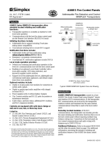
Description
The CA-6500 Class A expander allows six notication circuits, two
PLINK circuits and the built-in SLC circuit to be wired for class A
operation. The Class A operation can be independently selected for
the PLINK and SLC circuits using the Potter Fire Panel Programmer
Software.
Installation
The CA-6500 is installed directly in the addressable control panel
enclosure using the supplied cable assembly and hardware.
1. Power the system down.
2. Slide the Class A expander into the opening on the bottom of
the control chassis. The tabs on the back of the CA-6500 Class
A expander must slide into the slots located in the control panel
chassis.
3. Secure the CA-6500 Class A expander using two #6-32x3/8”
screws.
4. Plug the 2 x 9 cable assembly (P/N 5210515) into the CA-6500
and control panel. See page 2 for wiring instructions
Technical Specications
Standby Current 60 mA
Alarm Current 100 mA
Ambient Operating
Temperature
32°F - 120°F (0°C - 49°C) 10%-93% @
30°C (86°F) non-condensing humidity
Maximum CA-6500
Expanders 1
Size (WxHxD) 10-1/4” x 1-1/8” x 5-1/8”
Compatible Panels
IPA-4000
AFC-1000
PFC-6800*
P400(R)*
*Legacy Product
Features
• Provides Class A connection for NACs, P-Link and SLC
• Mounts to framework inside panel enclosure
• Allows for independent circuit selection of Class A operation
• Product includes a 5 year warranty
• UUKL Listed for Smoke Control
firealarmresources.com

PAGE 2 OF 2
Potter Electric Signal Company, LLC • St. Louis, MO • Phone: 800-325-3936 • www.pottersignal.com
8830123 - REV C • 12/18
CA-6500
Class A Expander
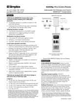
Examples of Installing and Wiring a Class A
Expander Card
CA-6500 Installation Showing the CA-6500
Ribbon Connection
#6-32 x 1/4
screws cA-6500
clAss A expAnder
slides in guides under mAin boArd
cA-6500 ribbon cAble cA-6500 ribbon cAble
DETAIL B
SCALE 1 : 1
CA-6500 Class A Expander Installation
The Class A conguration requires the use of the CA-6500. Once the
card is installed, the additional terminals are provided for the return
loop of the NAC. The CA-6500 provides the terminals for NACs,
SLCs, and P-Link. Refer to the gures below for examples of install-
ing and wiring a Class A expander card.
Notes:
1. One (1) CA-6500 Class A expander may be installed per panel.
2. The CA-6500 provides the terminals for NACs, P-Link, and SLCs.
Example of Wiring a Class A Expander Card
NAC 1 NAC 2
- + - +
Notification
Appliance
NAC 1 NAC 2
- + - +
NAC 3 NAC 4
- + - +
NAC 5 NAC 6
- + - +
NAC 3 NAC 4
- + - +
NAC 5 NAC 6
- + - +
Example of P-Link Class A Wiring Requiring a
CA-6500
P-LINK 2
- + A B
CA-6500
Connection
P-LINK 1
- + A B
- + A B
Expansion
Device
- + A B
Expansion
Device
P-LINK 2
- + A B
Panel
Connection
P-LINK 1
- + A B
Refer to the control panel’s Installation and
Programming manual for wiring Class A circuits
Fig 1 Fig 2
Fig 3
Fig 4
Ordering Information
Model Description Stock No.
CA-6500 Class A Expander 3992663
firealarmresources.com
/