Page is loading ...

Input
Out-
put
Output Power 120 watts
Technical Data
Installation and Operation
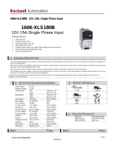
Three Phase DIN Rail Mountable
Switching Power Supply
8mm (0.31")
Connector size range
* AWG24 - 10
- Input connector can withstand torque at maximum
1.01Nm (9lb-in)
- Output connector can withstand torque at maximum
0.621Nm (5.5lb-in)
o
Use copper conductors only, 60/75 C (140/167°F)
o
Max. surrounding air temperature 55 C (122°F) for UL508
SPD241203
24 : Output Voltage
12 .... 12Vdc output
24 .... 24Vdc output

Power out [ % ]
1
2
o
Temperature [ C ]
0
100
71
-40 61
75
65
40
1
2
Three phase
Dual phase
DM194-A1
Application
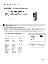
This unit is a primary switched-mode power supply designed
for use in panel-board installations or building-in
applications where access to the supply is restricted (shock-
hazard protection). It must only be installed and put into service
appropriately by qualified personnel.
Installation
Mounting
Front elements
Connection / Internal fuse
Removal from DIN Rail
Insert a flat screwdriver into the slot in the clamp. Pull down
the clamp out until the clamp clicks, and turn the switching
power supply bottom out. (See Fig. 4)
Removal
Mounting
Permissible mounting position: see Fig. 1 keep free ventilation
hole, leave space for cooling! Recommended to have 25mm
free space at all sides for ventilation / cooling:
see supplementary sheet "Technical Data".
(See Fig. 2)
Snap on support rail
Tilt the unit slightly rearwards.
Fit the unit over top hat rail.
Slide it downward until it hits the stop.
Press against the bottom front side for locking.
Shake the unit slightly to check the locking action.
Connection
Data for permitted loads, cable cross-sections and stripping:
see enclosed leaflet " Technical Data " (See Fig. 3).
Use only commercial cables designed for the indicated voltage
and current values!
With flexible cables: make sure that all stranded cable are secured
in the terminal.
Ensure proper polarity at output terminals!
Grounding
Do not operate without PE connection! To comply with
EMC and safety standards (CE mark, approvals), the unit must
only be operated if the PE terminal is connected to the
non-fused earth conductor.
Secondary side is not earthed; if necessary the or terminal
can be earthed optionally.
Internal fuse
The internal input fuse serves to protect the unit and must
not be replaced by the user. In case of an internal defect, the
unit must be returned to the manufacturer for safety reasons.
+
-
External circuit breaker
For input line protection observe national regulations; recommended
recommended circuit breaker: Mitsubishi, Type NF30-CS, rated
20A max or equipollent of TUV/VDE/UL approved sources.
Read Instructions!
Before working with this unit, read these instructions carefully and
completely. Make sure that you have understood all the information!
Disconnect system from supply network
Before any installation, maintenance or modification work:
Disconnect your system from the supply network. Ensure that cannot
be re-connected inadvertently!
In operation: No modifications!
As long as the unit is in operation: do not modify the
installation! The same applies also to the secondary side. Risk of
electric arcs and electric shock (fatal)!
Only (dis) connect plug connectors when
the power is off!
Convection cooling
Do not cover any ventilation holes!
Leave sufficient space around the unit for cooling!
See supplementary sheet "Technical Data" and Fig. 1
Warning: High voltage! Store energy!
The unit contains unprotected conductors carrying a lethal high voltage,
and components storing substantial amounts of energy. Improper
handling may result in an electric shock or serious burn!
The unit must not be opened except appropriately trained
personnel!
Do not introduce any object into the unit!
Keep away from fire and water!
Before start of operation
Ensure appropriate installation
Warning! Improper installation / operation impair safety and result
in operational difficulties or complete failure of the unit.
The unit must be installed and put into service appropriately by qualified
personnel. Compliance with the relevant regulations must be ensured.
Before operation is begun the following conditions must be ensured,
in particular:
Connection to main power supply in compliance with VDE0100
and EN50178.
With stranded wires: all strands must be secured in the terminal
blocks (Potential danger of short circuit).
Unit and power supply cables must be properly fused; if necessary
a manually controlled disconnecting element must be used to disengage
from supply mains.
The non-fused earth conductor must be connected to the " "
terminal (protection class 1).
All output lines must be rated for the power supply output current
and must be connected with the correct polarity.
Sufficient air-cooling must be ensured.
Use in a pollution degree 2 environment.
This equipment is suitable for use in class I, division 2, groups A, B,
C, and D or non hazardous locations only.
Warning-explosion hazard-substitution of components may impair
suitability for class I, division 2.
Warning-explosion hazard-do not disconnect equipment unless power
has been switched off or it is known to be the non-hazardous area.
Safety notes
Technical Data All specifications are typical at norminal line, full load,
25 ; Unless otherwise noticed.
oC
Vo [V] Io [A] Eff.
[typ.]
Inrush Current
400/500Vac
120 12
24
10
5
87%
89% < 12A
Output
Power
General Specification
Isolation ................................ 3000 Vac / 4242 Vdc
Isolation Resistance................. 100 M ohm
Operation amb. Temperature .... -40 ~ +71
Storage Temperature ............... -40 ~ +85
Derating................................. +61 ~ +71
Relative Humidity.................... 20 ~ 95% RH
Cooling .................................. Free air convection
Temperature Coefficient ........... 0.03% /
Dimension.............................. L124 x W74.3 x D118.8 [mm]
Weight................................... 800g
oC
oC
oC (see Fig. 5)
oC
Input Specification Fig. 5 Derating
Control And Protection
Input Internal Fuse............... 2A / 600 Vac internal / phase
Output Short Circuit ............. Hiccup mode
Output Over Load ................. 115 % ~ 135 %
Approvals And Standard
UL / cUL.............................. UL 508 Listed, UL 60950-1 Recognized
ISA 12.12.01
TUV. ................................... E N 60950-1
EN 61558-1, EN 61558-2-17
CE ...................................... EN 61000-6-3, EN 55022 class B
EN 61000-3-2, EN61000-3-3
EN 61000-6-2, EN 55024
EN 61000-4-2, -3, -4, -5, -6, -8, -11
EN 61204-3
Output Specification
Output Accuracy.................... +0 ~ 1%
Line Regulation ..................... ± 1%
Load Regulation .................... ± 1 %
Ripple & Noise ...................... 100 mV
Voltage Trim Range ............... 11.4 ~ 14.5 Vdc for 12V model
22.5 ~ 28.5 Vdc for 24V model
DC ON Indicator.................... Green LED
DC LOW Indicator.................. Red LED
Turn on time......................... <1000ms
Fall time............................... <150ms
Rise time.............................. <150ms
Hold Up Time........................ >20ms
Case m aterial. ....................... Metal
Rated Input Voltage ................. 3 4 00-500 V ac
Input Voltage Range................ (1) 3 AC IN 340 ~ 575 Vac 47-63Hz
(2) 2 AC IN 340 ~ 575 Vac 47-63Hz
(but output is power derated to 75%)
(3) DC IN 480 ~ 820 Vdc
Rated Input Current................. 0.5A
Line Frequency........................ 47 - 63 Hz
Power Factor........................... 0.55
o
o
o
11/2010
Operation indicator
The green LED lights up while the PSU working properly.
DC output low indicator
The red LED lights up while the output voltage is too low.
Potentiometer
Setting the output voltage.
/