SPD
Electrical protection
handbook
Based on the 2017 NEC®
Selecting Protective Devices

Selecting protective devices
Introduction
Welcome to Eaton’s Bussmann series Selecting Protective
Devices (SPD) handbook. This reference document is
based on the 2017 National Electrical Code (NEC®) and is a
comprehensive guide to electrical overcurrent protection and
electrical design considerations. The information within this
resource is presented on numerous applications as well as
code and standard requirements for a variety of electrical
equipment and distribution systems.
For this edition, considerable change was made to the
overall structure and organization to improve readability, and
to organize the discussions around the important topics of
safety and protection.
This edition is comprised of major sections containing
content that can be easily located by three methods.
• Table of contents with new or expanded content
highlighted in red.
• Index arranged alphabetically by topic with corresponding
page numbers
• NEC index to located information associated with specific
code references.
For more technical resources and general product
information, visit Eaton.com/bussmannseries.
This handbook is intended to clearly present product data and technical
information that will help the end user with design applications. Eaton reserves
the right, without notice, to change design or construction of any products and
to discontinue or limit their distribution. Eaton also reserves the right to change
or update, without notice, any technical information contained in this handbook.
Once a product has been selected, it should be tested by the user in all possible
applications. Further, Eaton takes no responsibility for errors or omissions
contained in this handbook, or for misapplication of any Bussmann series product.
Extensive product and application information is available online at: Eaton.com/
bussmannseries
National Electrical Code® is a trademark of the National Fire Protection Association,
Inc., Batterymarch Park, Quincy, Massachusetts, for a triennial electrical
publication. The term, National Electrical Code, as used herein means the triennial
publication constituting the National Electrical Code and is used with permission of
the National Fire Protection Association, Inc.
George Ockuly
This 2018 Edition of the Bussmann series Selecting Protective Devices
(SPD) handbook is dedicated to George Ockuly for his service to the
electrical industry.
Ockuly joined Bussmann
in 1972, where he held
various positions of
increasing importance,
including district sales
engineer, regional
sales manager, director
of North American
sales, and finally vice-
president of sales. His
responsibilities included
worldwide codes and
standards activities,
technical literature
development, application
engineering, product
certification and testing,
training, and product
safety. Mr. Ockuly retired
after 28 years of service.
Outside of Bussmann,
Ockuly held positions
on NEMA’s Standards
Policy Committee,
the International and
Regional Standards
Committee, the fuse
section, and served as
vice chairman of the
Codes and Standards
Committee.
He was a member of the NFPA Board of Directors, a member of the
National Electrical Code Panels 10 and 11, and was a principal on NFPA
70B Recommended Practices for Electrical Equipment Maintenance.
He served as vice-president of the U.S. National Committee of the
International Electrotechnical Commission (USNC/IEC), and technical
advisor for UNSC, IEC C32B Low Voltage Fuses. He is a senior member
of the Institute of Electrical and Electronics Engineers (IEEE), a member
of the Electronic Industries Alliance, and an associate member of the
International Association of Electrical Inspectors (IAEI). He is a recipient
of the NEMA Kite and Key award which recognizes individuals who
have advanced the interests of the electrical industry through active and
sustained involvement in the affairs of the association.
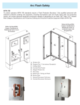
About the front cover
Electricians installing a Bussmann series Quik-Spec™ Coordination
Panelboard (QSCP) which uses the Compact Circuit Protector and UL®
Class CF CUBEFuse™. The QSCP makes it easy to achieve selective
coordination by using published upstream fuse and circuit breaker
tables. Available in flush- or surface-mount NEMA 1 enclosures or a
NEMA 3R enclosure, the QSCP increases worker electrical safety by
featuring dead front protection and finger-safe fuses.

Selecting protective devices
1
Benefits of the modern current-limiting fuse
Provides a flexible and worry-free solution
• With interrupting ratings up to 300 kA, fuses can be installed
in almost any system without fear of misapplication
• With straight voltage ratings, fuses can be installed in any
system independent of its grounding as opposed to slash
voltage rated devices that can only be installed on a solidly
grounded Wye system
• The fuse’s interrupting rating is typically at least equal to, or in
many cases greater than, the available fault current at the line
terminals
• The fuse’s high interrupting rating provides flexibility should
system changes, such as utility transformers or equipment
relocation, increase fault current levels
Increases electrical safety
• Finger-safe protection is provided in the latest fuse technology
for fuse holders and blocks, switches, and power distribution
fuse blocks, including the patented Bussmann™ series
Low-Peak™ CUBEFuse™ and revolutionary Compact Circuit
Protector (CCP) disconnect switch
• With interrupting ratings up to 300 kA, available fault currents
exceeding these high values due to system changes is
virtually eliminated
• UL Class branch circuit fuses have physical rejection features
that help ensure the same voltage and equal to or greater
interrupting ratings are retained throughout the system’s life
• Arc flash hazards can be greatly reduced when fuses operate
in their current-limiting range
Reduces risk and improved reliability
• Fuse rejection features reduce the potential to install
an overcurrent protective device (OCPD) with different
performance characteristics and lower interrupting ratings that
can compromise the protection level
• Fuses do not vent during a fault, safely containing and
extinguishing the arcing inside the fuse body. On some
OCPDs venting is inherent, possibly causing damage to other
system components
• Factory-calibrated replacement fuses ensure the same
protection level throughout the system’s life and eliminate the
possible need to test and recalibrate an OCPD after a fault
• The fuse’s enclosed, sand-filled design operates on proven
thermal principles that eliminate the risk something may not
be properly adjusted or operate correctly under short-circuit
conditions as is the case with some mechanical OCPDs
• The enclosed, fixed design eliminates the need to adjust and
change device settings in the field, thus reducing confusion
and risk of misapplication
Saves time and money
• Fuses eliminate the need for expensive, time-consuming fault
current studies when using 300 kA interrupting rated Low-
Peak fuses
• Current-limiting fuses make achieving selective coordination
easy and simple by maintaining a minimum amp ratio
between upstream and downstream fuses. Using published
ratio tables eliminates the need for selective coordination
studies and ensures the affected circuits are isolated and
prevents unnecessary power loss to upstream portions of the
electrical system.
• Because fuses are an enclosed, non-venting design, they
eliminate the need for additional system guards or barriers to
protect from venting
• Fuses reduce the need for OCPD maintenance as they require
no additional maintenance or servicing beyond periodically
checking conductors and terminations
Helps achieve high equipment short-circuit current ratings
(SCCR)
• Fuses have high interrupting ratings (up to 300 kA) and will
not be the limiting factor in a panel SCCR
• Current limitation drastically reduces the peak let-through
current to protect downstream components and help raise
branch SCCRs
Reduces downtime and improved protection
• Specifying Type 2 “No Damage” (versus Type 1) protection
with properly sized current-limiting fuses helps eliminate the
need to replace components after a fault
• Current limitation helps reduce the extreme, destructive
thermal and mechanical forces associated with short-circuit
events
Facilitates code compliance
• Compliance with NEC 110.9 is easily achieved with high
interrupting ratings up to 300 kA
• Compliance with NEC 110.10 for protecting equipment and
components from extensive damage from short-circuits is
easy with current-limiting fuses
• Compliance with OSHA 1910.334(b)2 is met by eliminating
the invitation for an operator to reset the OCPD after a fault
without first determining its cause. Resetting circuit breakers
or replacing fuses without investigating and fixing the cause is
prohibited by federal law.
1-1
Eaton.com/bussmannseries

Selecting protective devices
Table of Contents
Section Topic Page
1 Benefits of the modern, current-limiting fuse 1-1
2 Electrical safety 2-1
3 Fuseology and breaker basics 3-1
3.1 Fuseology 3-1
3.2 Breaker basics 3-54
4 Power system analysis 4-1
4.1 Fault current calculations 4-1
4.2 Selective coordination 4-11
4.3 Arc flash 4-30
5 Maintenance 5-1
5.1 Overview 5-1
5.2 Maintenance frequency and procedures 5-1
5.3 MCCB maintenance example 5-2
5.4 Circuit beaker testing considerations 5-2
5.5 OCPD servicing and maintenance 5-3
5.6 Testing knifeblade fuses 5-3
5.7 After an OCPD opens 5-3
5.8 Calibration decal on equipment 5-3
6 Electrical safe work practices 6-1
6.1 Overview 6-1
6.2 The electrical safety program 6-1
6.3 Shock hazard 6-2
6.4 Arc flash hazard 6-5
6.5 Maintenance 6-13
7 Equipment application/protection 7-1
Fuse sizing for building electrical systems up to 600 V 7-1
7.1 Appliances 7-4
7.2 Ballasts 7-4
7.3 Batteries/battery charging 7-5
7.4 Busway 7-5
7.5 Capacitors 7-7
7.6 Circuit breakers 7-7
7.7 Conductors 7-25
7.8 Electric heat 7-44
7.9 Elevators 7-44
7.10 Generator protection 7-48
7.11 Ground fault protection 7-48
7.12 Industrial control panels 7-55
7.13 Industrial machinery 7-76
7.14 Motor/motor circuit protection 7-76
7.15 Panelboards and other fusible equipment 7-139
7.16 Solenoids 7-143
7.17 Switchboards 7-144
7.18 Transfer switches 7-147
7.19 Transformers 7-152
7.20 Uninterruptible Power Supplies (UPS) 7-158
7.21 Variable frequency drive and power
electronic device protection 7-159
7.22 Welders 7-162
Section Topic Page
8 Special applications 8-1
8.1 Data centers 8-1
8.2 HVAC systems 8-10
8.3 Photovoltaic power generation 8-12
8.4 Fuse applications in hazardous locations 8-20
9 Appendix 9-1
9.1 Electrical formulas 9-1
9.2 Glossary of common electrical terms 9-2
9.3 Selective coordination inspection form 9-4
9.4 Interrupting rating and short-circuit
current rating inspection form 9-5
9.5 Content index related to the 2017 NEC 9-8
9.6 Content index related to the 2018 NFPA 70E 9-8
9.7 Content index related to the OSHA CFR 1910 9-8
9.8 Content index by subject 9-8
1-2 Eaton.com/bussmannseries

Selecting protective devices
2
2 Electrical safety
The safety implications for electrical system design, installation,
inspection, testing, maintenance, trouble-shooting and repair are
significant.
In most cases, applicable enforceable codes and standards provide
requirements that are the minimum for safety. In order to provide
electrical systems and equipment well suited for the owner’s
environment and needs, designers and installers must go beyond
these minimum requirements to provide systems and equipment that
are efficient and adequate for the present and to easily accommodate
future changes. There may also be additional safety features that can be
incorporated beyond the minimum required by Codes and standards.
In some cases, this publication on Selecting Protective Devices (SPD)
for overcurrent protection applications presents solutions that merely
meet the minimum Code requirements. For other cases, there are
recommended solutions that provide superior safety, reliability and
practicality.
Safety in regards to electrical equipment and systems has evolved to
mean more than just protecting people and property against shock
and fire hazards due to equipment failures. It includes considerations
for electrical systems that deliver electrical power to loads vital for
life safety and public safety, such as emergency systems and critical
power operations systems. In these cases, the code and standard
requirements focus on electrical system reliability and power continuity
to the loads which are vital for life and public safety.
Another safety prospective is electrical safety related work practices.
Federal regulations mandated by OSHA require owners to provide a safe
workplace. This includes workers who must work on or near electrical
equipment and systems. The hazards of electrical shock, arc flash and
arc blast can be eliminated or mitigated by good design practices,
proper installation and maintenance procedures.
Selecting and using overcurrent protective devices (OCPDs) can have a
profound impact on the level of safety an electrical system provides. To
that end, this handbook covers many subjects associated with selecting
overcurrent protective devices:
• Fuseology and breaker basics cover how overcurrent devices work,
their varieties, ratings and operating characteristics that make them
suitable for various applications.
• Power system analysis, covered in Section 4 examines fault currents,
selective coordination and arc flash that directly related to electrical
system safety and reliability. Specifically covered is this section are
the National Electrical Code (NEC®) requirements related to these
subjects.
• The impact maintenance, or the lack there of, has on ensuring
overcurrent protective device operation and performance over time is
covered in Section 5.
• Electrical safe work practices focuses on NFPA 70E and OSHA
requirements, and how to ensure worker safety.
• Equipment application and protection deals with applying OCPDs
for various applications, and why some are better suited for use
with regards to operation, reliability, electrical safety and reducing or
eliminating equipment damage.
Our section on special applications focuses on those considerations
unique to protecting data centers, HVAC and photovoltaic systems, and
fuses used in hazardous locations.
All the sections described above can stand on their own, but they
also interrelate. Taken all together, they will provide a comprehensive
understanding about selecting protective devices for reliability, code,
standards and regulatory compliance, and, most importantly, safety for
people, plant and equipment.
Fault currents release tremendous amounts of destructive energy and
magnetic force. Selecting the correct overcurrent protective device can
help ensure they do not result in a short-circuit event like the one shown
above.
2-1
Eaton.com/bussmannseries

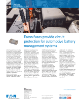
The revolutionary Bussmann™ series Low-Peak™
CUBEFuse™ delivers the smallest footprint
compared to any Class J or RK fuse solution —
requiring up to 70% less space when combined
with its unique fuse holder or UL® 98 Listed
Compact Circuit Protector.
Freeing up space is powerful. And the CUBEFuse
does just that, while packing up to a 300 kA
interrupting rating and enabling higher panel
SCCR. Plus, it features plug-in capability for
easier installation.
What will you do with all that space?
CUBEFuse.com
The evolution continues. 2018.
The revolutionary
CUBEFuse™
compared to any Class J or RK fuse solution —
requiring up to 70% less space when combined
with its unique fuse holder or UL
Compact Circuit Protector.
Freeing up space is powerful. And the CUBEFuse
does just that, while packing up to a 300 kA
interrupting rating and enabling higher panel
SCCR. Plus, it features plug-in capability for
easier installation.
What will you do with all that space?
The power of space

Selecting protective devices
3
First published in the 1920s, the Bussmann Fuseology handbook on
fuses has promoted electrical safety by advancing the understanding of
overcurrent protection.
3 Fuseology and breaker basics
Contents Section page
3.1 Fuseology 1
3.2 Breaker basics 54
Sidebars
Sidebars in this handbook contain additional
information or present related subject material
Look for these in the yellow boxes Section page
• Friemel’s Laws of Overcurrent Protection 3
• Factory calibrated replacements 4
• Single-phasing…does it have issues with fuses? 8
• The Bussmann series Low-Peak fuse system 9
• The NEC and “Fuse only ratings” 11
• Test conditions for a 300 kA interrupting rated fuse 14
• Selective coordination 30
• Exceptions in the code for applying supplemental OCPDs 39
• 10 Reasons why supplemental protectors are not allowed
to protect branch circuits 41
• Rules for medium voltage current-limiting fuses 44
• R-Rated medium voltage fuses and motor circuits 45
3.1 Fuseology
Contents Section page
3.1.1 Overcurrent protective device basics 2
3.1.1.2 Friemel’s Laws of Overcurrent Protection 2
3.1.2 How fuses work 3
3.1.2.1 Overcurrent protection, overloads and short-circuits 3
3.1.3 Construction 4
3.1.3.1 Non-time delay (fast-acting) fuses 5
3.1.3.2 Dual-element, time-delay fuses 6
3.1.4 Ratings 9
3.1.4.1 Volts 9
3.1.4.2 Amps 10
3.1.4.3 Interrupting rating 11
3.1.5 Performance characteristics 16
3.1.5.1 Current limitation/fuse current let-through curves 16
3.1.5.2 Current let-through curves 20
3.1.5.3 The OCPD’s role in electrical safety 26
3.1.5.4 Time-current characteristic curve (TCC) 29
3.1.5.5 Selective coordination 30
3.1.6 Fuse types and classes 31
3.1.6.1 Low voltage branch circuit fuses 31
3.1.6.2 Supplemental/application limited OCPDs 39
3.1.6.3 Medium voltage fuses 44
3.1.6.4 High speed fuses 48
3.1.6.5 Photovoltaic fuses 51
3.1.7 Fuseology summary —
the power of the modern, current-limiting fuse 53
3-1
Eaton.com/bussmannseries

Section 3 — Fuseology and breaker basics
3.1.1 Overcurrent protective device basics
Fuseology is the study of the fuse’s fundamental operating principles.
These include the ratings and operating characteristics that make the
fuse an efficient overcurrent protective device (OCPD) as well as its
construction that creates its unique leadership role in circuit protection.
In the simplest terms, a fuse is an overcurrent protective device with a
circuit-opening fusible part that is heated and severed by the passage of
overcurrent through it.
A fuse is comprised of all the parts that form a unit that can perform
these functions. It may or may not be the complete device necessary to
connect it into an electrical circuit.
Electrical distribution systems can be simple or complicated.
Regardless, they cannot be absolutely fail-safe and are subject to
destructive overcurrent events such as overloads, ground faults or
short-circuits. Harsh environments, general deterioration, damage
(whether accidental or from natural causes), excessive electrical system
expansion or overloading are common factors leading to overcurrent
events. Reliable OCPDs like the fuse shown in Figure 3.1.1.a prevent
or minimize costly damage to transformers, conductors, motors and
many other components and loads that make up a complete power
distribution system. Reliable circuit protection is also essential to
electrical safety for personnel as well as avoiding severe monetary
losses from power blackouts or prolonged facility downtime.
Figure 3.1.1.a A regular and x-ray view of the Bussmann™ series Low-Peak™ LPN-RK
dual-element fuse showing the overload and short-circuit links.
The fuse is a reliable and simple OCPD made in a variety of
configurations that are fundamentally comprised of a “fusible” link or
links encapsulated in a tube or housing that are connected to terminals.
The link’s electrical resistance is so low that it acts as a conductor until
it encounters current levels above its amp rating. Then it melts and
opens the circuit to protect conductors, components and loads.
Fuses for electrical distribution systems typically have three unique
performance characteristics that address Friemel’s Laws of Overcurrent
Protection (see sidebar “Friemel’s Laws of Overcurrent Protection” for
details):
• High interrupting rating to safely open very high fault currents without
rupturing.
• Current limitation to “limit” fault currents to low values for optimum
component and equipment protection, and help equipment achieve
high short-circuit current ratings (SCCRs).
• Electrical system selective coordination for the full range of
overcurrent events to help prevent needless “blackouts” caused by
upstream OCPDs cascading open when applied with the correct amp
rating ratios.
3.1.1.2 Friemel’s Laws of Overcurrent Protection and the
NEC
Law 1 — Interrupting rating
• OCPDs shall be applied with an interrupting rating equal to or greater
than the maximum available fault current
• Code compliance: 110.9
Law 2 — Component protection
• OCPDs shall be selected and installed to clear a fault without
extensive damage to electrical equipment and components
• Code compliance: 110.10
Law 3 — Selective coordination
• A properly engineered and installed electrical system will restrict
outages to ONLY the nearest upstream OCPD for the full range of
overcurrents and associated opening times, leaving the remainder of
the system undisturbed and preserving service continuity
• Code compliance: 620.62, 645.27, 695.3(C)(3), 700.32, 701.27, 708.54
Friemel’s Law Code section How it’s achieved
1. Interrupting
rating 110.9 Current limiting fuses,
especially Low-Peak
2. Component
protection
110.10 and numerous
sections involving SCCR
Current limiting fuses,
especially Low-Peak and
high SCCR control panel
products (CCP, PDFB,
etc.)
3. Selective
Coordination
620.62, 645.27, 695.3,
700.32, 701.27, 708.54
Current limiting fuses,
especially Low-Peak,
QSCP, Power Module,
CCPLP and engineering
services
Figure 3.1.1.2.a Friemel’s Laws of Overcurrent Protection in table form.
3-2 Eaton.com/bussmannseries

Selecting protective devices
3
Friemel’s Laws of Overcurrent Protection
Paul Friemel was known in the electrical industry as the Professor
of Overcurrent Protection from the mid-1960s until his passing in
2015. As a licensed professional engineer, he presented seminars
on electrical overcurrent protection for more than 40 years.
Among his many accolades, he was awarded the Outstanding
Educator Award by the IEEE as a Life Senior Member in 2004 and
recognized as an Outstanding Professional Engineer by the St.
Louis Society of Professional Engineers in 2010. He served on the
St. Louis Electrical Code Review Committee for St. Louis County
for over two decades, actively participated in the International
Association of Electrical Inspectors, and was a guest lecturer at
Washington University and the University of Missouri. He was
a long standing member of the Electrical Board of Missouri and
Illinois where he served several terms on the board of directors.
Friemel taught the three C’s of overcurrent protection which are
now known as Friemel’s Laws of Overcurrent Protection:
1. Interrupting rating (Capacity)
2. Component Protection
3. Selective Coordination
An understanding of these three key electrical overcurrent
protection principles will lead to a safe, reliable and code compliant
electrical system.
3.1.2 How fuses work
As an overcurrent protective device, the fuse acts as “electricity’s safety
valve” by providing a weak link in the circuit path that, when properly
applied, will melt and open the circuit to minimize or eliminate any
damage that can be caused by an excessive flow of current. There are
many fuse varieties and constructions, each developed to address an
application’s need for a particular kind of overcurrent protection.
3.1.2.1 Overcurrent protection
An overcurrent is either an overload or a fault/short-circuit. The
overload current is an excessive current flow relative to normal operating
current, but still confined to the normal circuit paths provided by the
conductors, components and loads. A fault (often referred to as a short-
circuit) flows outside the normal circuit paths.
Overloads
Overloads are most often up to 6 times the normal current level. They
are usually caused by harmless, temporary in-rush currents that occur
when motors start up or transformers are energized. Such overloads,
or transients, are normal occurrences, and their brief duration is not
harmful to circuit components as the associated temperature rise is
minimal with no harmful affect. It’s important that OCPDs are properly
sized and have the appropriate operating characteristics so they do not
react to these temporary overloads or cause “nuisance openings.”
Persistent, non-temporary overloads can result from defective motors
(worn bearings) or when too many loads are on a single circuit and
must not be permitted to last long enough to damage electrical system
components such as conductors. This damage may eventually lead to
severe fault events if the overload is not interrupted.
Due to the overload’s inherent low magnitude nature, removing them
within seconds or even minutes will generally prevent thermal damage.
Faults
Faults, also referred to as short-circuits, differ from overloads as
they can be hundreds to thousands of times greater than the normal
operating current. A high level short-circuit may be up to 30 kA or 200
kA, and must be interrupted as quickly as possible to minimize the
damage that can include:
• High magnetic forces that warp and distort busbars and associated
bracing beyond repair
• Severe insulation damage
• Melting or vaporizing conductors
• Vaporizing metal, including buswork in electrical equipment
• Ionized gases
• Arcing fires
• Explosions
Note: “fault current” is a general term that’s used in this publication and
includes ground fault, arcing fault and short-circuit currents.
3-3
Eaton.com/bussmannseries

Section 3 — Fuseology and breaker basics
3.1.3 Construction
The fuse is a highly efficient OCPD with a simple design based upon
basic principles of physics to interrupt and limit overcurrent events.
Insight into their construction helps in understanding their application.
As shown in Figure 3.1.3.a, fuses have four parts common to most
designs: case/housings (tube or cartridge), terminals (end blades or
ferrules), fuse link (element), and arc-quenching filler. There are different
fuse types that provide the operating characteristics required to address
differing circuit protection needs.
Arc-quenching filler
End blades Fuse linkTube/cartridge
Figure 3.1.3.a A dual-element, time-delay Low-Peak LPS-RK fuse
showing the four common construction characteristics.
A fuse’s construction typically offers these benefits:
Physical rejection — Fuses have rejection features based on physical
size or by a construction characteristic. Generally, a fuse of one class
and case size cannot be installed in another fuse class and case size
mounting. This ensures that the replacement fuse being installed will
have the same voltage and interrupting ratings. A mild exception is
that Class R fuses can be installed in Class H(K) fuse mountings for a
protection upgrade, but, lower performing Class H(K) fuses cannot be
installed in Class R fuse holders or blocks.
The Class J fuse is another example. Its size rejection prevents installing
any other fuse type and virtually eliminates installing the wrong fuse
type having different, potentially lower performance characteristics.
Unless a user replaces the holder, block or switch, it’s very difficult to
install the wrong replacement fuse.
Enclosed, non-venting design — Fuses do not vent when they
interrupt fault currents. All arcing is contained and extinguished
inside the fuse body. This reduces the risk of metal vapors causing
unnecessary damage to other components inside an enclosure. As part
of their design, some mechanical OCPDs will vent when they interrupt
fault currents. In addition, using fuses reduces cost by eliminating the
need for guards or barriers to protect from the venting.
Enclosed, fixed, thermal design — Modern current-limiting fuses are
constructed with an enclosed case, tube or body and have no moving
parts when they open from an overcurrent. By operating on thermal
energy principles of physics, the fuse improves electrical system
reliability by not relying on springs, levers or latches that require periodic
maintenance to ensure continued proper operation.
Factory calibrated replacements
There is no worry that a fuse may seize or not operate as intended
as it’s factory calibrated with no need for field adjustment. This
minimizes possible misapplication by eliminating the need to adjust
or change device settings in the field. Engineers and specifiers
can be certain the required overcurrent protection level is met and
retained.
When fuses are replaced, system integrity is maintained by
ensuring the same protection for many years to come.
Using thermal or electronic OCPDs in electrical systems to protect
against overloads, such as motor starters, is beneficial as they can
easily be reset by an operator or user (after the overload cause
has been corrected) so that production can quickly resume. On the
other hand, if a fault occurs, a qualified electrician must investigate
and remedy the cause prior to resetting the device or replacing the
fuse. If an unqualified person is allowed to simply reset a device, a
safety hazard could occur if the fault is still on the line.
Fuses help in complying with federal law and other safety
standards by eliminating the invitation for an operator to “reset”
a device after a fault without investigating or remedying the
cause. OSHA 1910.334(b)2 does not allow this practice and
similar requirements are found in NFPA 70E Section 130. Fuses
help prevent this from happening as a qualified person is much
more likely to be involved in replacing the fuse. In addition, many
maintenance personnel in industrial facilities prefer fuses for the
simple reason that the troubleshooter is more likely to investigate
the cause for the fuse opening rather than simply replacing the
fuse.
3-4 Eaton.com/bussmannseries

Selecting protective devices
3
3.1.3.1 Non-time-delay fuse
Depending upon the fuse’s amp rating, the “single-element” non-time
delay fuse (often called a fast-acting fuse) may have one or more links.
They are electrically connected to the terminals (end blades or ferrules)
(see Figure 3.1.3.1.a) and enclosed in a case/housing (tube or cartridge)
that contains an arc-quenching filler material that surrounds the link.
Many Bussmann series Limitron™ fuses are “single-element” fuses.
Under normal operation, when the fuse is applied at or near its amp
rating, it simply functions as a conductor. If an overload occurs and
persists for more than a short time interval, as illustrated in Figure
3.1.3.1.b, the link’s temperature eventually reaches a level that causes a
restricted link segment (neck) to melt. As a result, a gap is formed and
an electric arc established. As the arc causes the link to “burn back,”
the gap becomes progressively larger. The electric arc’s resistance
eventually reaches such a high level that it cannot be sustained and
is extinguished with the help of the filler material’s arc-quenching
properties (see Figure 3.1.3.1.c). The fuse will have then completely cut
off all current flow in the circuit.
Present day single-element fuse designs respond very quickly to
overcurrents with excellent fault current component protection.
However, temporary, harmless overloads (in-rush currents associated
with inductive loads such as motors, transformers and solenoids) may
cause nuisance openings unless these fuses are oversized. Therefore,
they are best used in circuits not subject to heavy inrush currents.
Whereas overload normally falls between 1.35 and 6 times normal
current, fault currents are quite high and the fuse may be subjected to
fault currents of 30 kA or higher. The fuse’s current-limiting response to
such high currents is extremely fast as its restricted link sections will
simultaneously melt within a matter of two or three-thousandths of a
second.
The multiple arcs’ high total resistance, together with the arc-quenching
filler material, results in rapid arc suppression and clearing the fault (see
Figures 3.1.3.1.d and Figure 3.1.3.1.e). Fault current is cut off in less than
a quarter-cycle, long before it can reach its full value (fuse operating in
its current-limiting range).
Figure 3.1.3.1.a Cutaway view of typical single-element fuse.
Figure 3.1.3.1.b Under sustained overload, a section of the link melts
and an arc is established.
Figure 3.1.3.1.c The “open” single-element fuse after opening a circuit
overload.
Figure 3.1.3.1.d When subjected to a fault current, several sections of
the fuse link melt almost instantly.
Figure 3.1.3.1.e The “open” single-element fuse after opening a shorted
circuit.
LPJ — Class J, 600 V, 300 kA IR
up to 600 A
JJN — Class T, 300 V, 200 kA IR
up to 1200 A
JJS — Class T, 600 V, 200 kA IR
up to 800 A
LPS-RK — Class RK1, 600 V, 300 kA IR
up to 600 A
FRS-R — Class RK5, 600 V, 200 kA IR
up to 600 A
LP-CC, FRQ-R, KTK-R — Class CC,
600 V, 200 kA IR up to 30 A
LPN-RK — Class RK1, 250 V, 300 kA IR
up to 600 A
FRN-R — Class RK5, 250 V, 200 kA IR
up to 600 A
Bussmann series UL Listed branch circuit fuses play a major role in industrial or commercial facilities by providing reliable, maximum protection to
power systems. Their physical size or rejection features prevent replacing a fuse with one from another fuse class. This helps ensure the correct
replacement fuse is always installed and the voltage and interrupting ratings remain the same. Shown are the case sizes for each fuse class relative
to the size of a US quarter (left edge of image).
3-5
Eaton.com/bussmannseries

Section 3 — Fuseology and breaker basics
3.1.3.2 Dual-element, time-delay fuse
There are many advantages to using “dual-element,” time-delay fuses
that feature an overload link and a short-circuit element connected in
series — hence, the “dual-element” designation. Unlike single-element
fuses, Bussmann series dual-element, time-delay fuses can be sized
closer to the load to provide high performance for both short-circuit and
overload protection.
The overload element provides the intentional “time-delay” that permits
temporary overloads to harmlessly pass. This is the reason these fuses
can be sized much closer to the load than non-time delay fuses that
must be oversized to pass inrush currents and not produce nuisance
openings.
The short-circuit element is there to handle fault currents, and when
the fuse is operating in its current-limiting range, it’s not possible for
the full available fault current to flow through the fuse — it’s a matter
of physics. The small restricted link sections in the short-circuit element
quickly vaporize with the filler material assisting in forcing the current to
zero; and so it’s able to “limit” the fault current.
Anatomy of a dual-element, time-delay fuse
Arc-quenching filler
Insulated end caps help
prevent accidental contact
with live blades
Overload element
Short-circuit element with “neck” restrictions
that arc and “burn back” under fault conditions.
The overload element is held in tension to the short-
circuit element by the trigger spring until the fusing
alloy fractures
The trigger spring pulls the overload element away
from the short-circuit element to open the fuse
Figure 3.1.3.2.a Typical Class R Low-Peak fuse.
The Low-Peak LPS-RK-100SP, 100 A, 600 V, Class RK1, dual-element
fuse has excellent time-delay to withstand high inrush currents along
with excellent current limitation and a 300 kA interrupting rating. Figure
3.1.3.2.a shows the fuse’s internal construction. The real fuse has a non-
transparent tube and arc-quenching material that completely surrounds
the element and fills the tube’s internal space.
Figure 3.1.3.2.b “Dual-element” construction.
The true dual-element fuse has separate and distinct overload and short-
circuit elements connected in series as shown in Figure 3.1.3.2.b.
Figure 3.1.3.2.c Overload element operation.
Operation under persistent overload conditions as shown in Figure
3.1.3.2.c causes the trigger spring to fracture the calibrated fusing alloy
and releases the “connector.” The insets show the overload element
before and after it opens. The coiled spring pushes the connector from
the short-circuit element and the circuit is interrupted.
Figure 3.1.3.2.d Short-circuit element operation under fault conditions.
For operation under fault conditions, the short-circuit element is
designed with minimum metal in the restricted portions to greatly
enhance the fuse’s current limitation and minimize the short-circuit
current let-through. Fault current causes the short-circuit element’s
restricted portions to quickly vaporize and commence arcing as shown
in Figure 3.1.3.2.d. The arcs burn back the element, resulting in longer
arcs that reduce the current with the arc-quenching filler helping to
extinguish the arcs and force the current to zero.
Figure 3.1.3.2.e Arc-quenching filler material helps suppress the arcing
by melting and forming folgurite.
As a result of short-circuit operation, the special small granular, arc-
quenching material plays an important part in the interruption process as
it assists in quenching the arcs by absorbing their thermal energy and
melting to form an insulating barrier material called folgurite as shown in
Figure 3.1.3.2.e.
3-6 Eaton.com/bussmannseries

Selecting protective devices
3
208 V
3-phase
10 Hp / 32.2 FLA
M
M10 Hp / 32.2 FLA
208 V
3-phase
Low-Peak or Limitron
dual element 150 A fuse
Low-Peak dual
element 40 A fuse
Limitron non-time
delay 90 A fuse
Low-Peak dual
element 150 A fuse
150 A:90 A = 1.67:1 inadequate
(minimum ratio must be at least 3:1)
150 A: 40 A = 3.75:1 adequate
(minimum ratio need only be 2:1)
Selective coordination
No selective coordination
200 V
3-phase
Low-Peak or Fusetron
dual-element fuse
10 Hp / 32.2 FLA
M
200 V
3-phase
Limitron non-time
delay 100 A fuse
10 Hp / 32.2 FLA
M
M
10 Hp / 32.2 FLA
200 V
3-phase
100 A switch
60 A switch
Fusetron dual
element 40 A fuse
Advantages of dual-element over single element fuses
Bussmann series dual-element, time-delay fuses have six distinct
advantages over single-element, non-time delay fuses:
1. Motor overload and short-circuit protection
When Bussmann series dual-element, time-delay fuses protect circuits
with high inrush currents, such as motors, transformers and other
inductive components, the Bussmann series Low-Peak and Fusetron™
dual-element, time-delay fuses can be sized close to full-load amps
to maximize overcurrent protection. Sized properly, they will hold until
normal, temporary overloads subside. For example, a 200 volt three-
phase 10 Hp motor with a 1.15 service factor has a 32.2 A full-load
current rating (see Figure 3.1.3.2.f).
Figure 3.1.3.2.f Motor circuit with a dual-element, time-delay fuse.
A 40 A, dual-element, time-delay fuse will protect the 32.2 A motor,
compared to a much larger, 100 A, non-time delay, single-element fuse
that would be necessary to withstand the temporary inrush current. If a
harmful, sustained 200% overload occurred in the motor circuit, the
100 A, non-time delay, single-element fuse would never open and the
motor would be damaged because it only provides ground fault and
short-circuit protection. Additionally, the non-time delay fused circuit
would require separate motor overload protection per the NEC. In
contrast, the 40 A time-delay dual-element fuse provides the same
ground fault and short-circuit protection, plus overload protection
(eliminating the code requirement for separate motor overload
protection) (see Figure 3.1.3.2.g).
Fuse and switch sizing for 10 Hp motor (200 V, 3 Ø, 32.2 FLA)
Fuse type Max fuse (A) Required switch (A)
Dual-element, time-delay
Fusetron FRS-R or FRN-R 40* 60
Single element non-time delay
Limitron 100†100
* Per NEC 430.32
† Per NEC 430.52
In normal installations, Bussmann series dual-element fuses sized for
motor-running, overload protection, provide better fault protection plus a
high degree of back up protection against motor burnout from overload
or single-phasing should other overload protective devices fail (see
sidebar “Single-phasing…are fuses an issue?” on page 3-8). If thermal
overloads, relays or contacts should fail to operate, the properly sized
dual-element fuse will act independently to provide “back-up” protection
for the motor.
When secondary single-phasing occurs, current in the remaining phases
increases from 173% to 200% of the motor’s rated full-load current.
When primary single-phasing occurs, unbalanced voltages occurring in
the motor circuit also cause excessive current. Dual-element fuses sized
for motor overload protection can help protect against overload damage
caused by single-phasing.
2. Permit using smaller and less costly switches
Bussmann series dual-element, time-delay fuses permit using smaller,
space saving and less costly switches because a properly sized higher
amp rated single-element fuse would make it necessary to use larger
switches as the switch rating must be equal to or larger than the fuse’s
amp rating. As a result, a larger switch may cost two or three times
more than necessary rather than using a dual-element Bussmann series
Low-Peak or Fusetron fuse. (Note: should a larger switch already be
installed for single-element fuses, smaller, properly sized dual-element
fuses can also be installed for motor overload or back-up protection
using fuse reducers. These permit installing a smaller case size fuse into
a larger case size mounting.)
3. Better short-circuit component protection (current limitation)
Bussmann series dual-element, time-delay fuses provide better
component protection than non-time delay, fast-acting fuses that must
be oversized for circuits with in-rush or temporary overloads. Oversized
non-time delay fuses respond slower to faults than smaller, time-delay
fuses because the current will build up to a higher level before the fuse
opens, thus the oversized fuse’s current limitation is less than a fuse
with an amp rating that’s closer to the circuit’s normal full-load current.
4. Simplify/improve selective coordination for blackout prevention
The larger an upstream fuse is relative to a downstream fuse (feeder to
branch), the less likely an overcurrent in the downstream circuit to cause
both fuses to open (lack of selective coordination). To be selectively
coordinated, Bussmann series Low-Peak fuses require only a 2:1 amp
rating ratio. Contrast this to a fast-acting, non-time delay fuse that
would require at least a 3:1 amp rating ratio between a large upstream,
lineside Low-Peak time-delay fuse and the downstream, loadside
Bussmann series Limitron fuse.
As shown in Figure 3.1.3.2.h, closely sized Bussmann series Low-Peak
dual-element fuses in the branch circuit for motor overload protection
provides a large difference in the amp ratings (3.75:1 ratio) between
the feeder and branch fuses, compared to the single-element, non-
time delay Limitron fuse (1.67:1 ratio) with the 90 A Limitron fuse not
conforming to the 3:1 published ratio needed for selective coordination.
Figure 3.1.3.2.g Closer fuse sizing to load can result in using smaller,
less costly switches.
Figure 3.1.3.2.h Using Low-Peak fuses permits closer fuse sizing to
load for better protection and using smaller, less costly switches while
retaining selective coordination to help prevent blackouts.
3-7
Eaton.com/bussmannseries

Section 3 — Fuseology and breaker basics
Single-phasing…are fuses an issue?
Single-phasing conditions on three-phase motor circuits can create
unbalanced voltage and/or overcurrent conditions that, if allowed
to persist, will damage motors. In modern motor circuits, properly
applied fuses and overload protective devices provide a high
degree of single-phasing protection. Major considerations of single-
phasing include the following.
• Single-phasing cannot be eliminated, there are numerous causes
including:
• The utility loses one phase
• Overheated conductor termination
• Disconnect does not “make” one pole
• Controller contact burns open
• Prior to 1971, single-phasing plagued three-phase motors
installed per the NEC because overload protection was only
required on two phases. The 1971 NEC remedied this problem
by adding the requirement for three-phase-motor circuits to have
motor overload protection on all three phases. This provided
protection for the worst condition seen when a utility loses a
phase on the transformer primary.
• Three properly sized (to the actual motor running current) motor
overload protective devices, now required in NEC 430.37, provide
sufficient protection
• Most electronic overloads, soft-start controllers, and drives have
options to sense voltage imbalance to provide single-phasing
protection
• Although circuit breakers do not cause single-phasing, unless
one pole’s contact does not “make,” they do not provide single-
phasing protection
• Fuses provide excellent short-circuit, current limitation to
protect motor circuit starters and conductors, including Type 2
“No-Damage” protection when properly sized
• Fusible motor control centers benefit from the fast clearing
time of a current-limiting fuse that also helps to reduce incident
energy levels, mitigate arc flash hazards and protect workers
Percent of rating or opening time
Ambient °F (°C)
150
140
130
120
110
100
90
80
70
60
50
40
30
-76 -40 -4 32 68 104 140 176 212
(-60) (-40) (-20) (0) (20) (40) (60) (80) (100)
Affect on carrying
capacity rating
Affect on
opening time
Ambient °F (°C)
120
110
100
90
-76 -40 -4 32 68 104 140 176 212
(-60) (-40) (-20) (0) (20) (40) (60) (80) (100)
Percent of rating or opening time
5. Better motor protection in elevated ambient temperatures
Before selecting a fuse or any OCPD, the application’s ambient
temperature should be known so the proper amp rating can be
determined through what’s called “derating.” Like all fuses, the
dual-element fuse should be derated based on increased ambient
temperatures. The fuse derating curves closely parallel motor derating
curves in elevated ambient temperatures. Figure 3.1.3.2.i illustrates the
affect ambient temperature has on Bussmann series Fusetron and Low-
Peak dual-element fuse operating characteristics. This unique feature
allows for optimum motor protection, even in high temperatures. For
derating affects of single-element or non-time delay fuses, see Figure
3.1.3.2.j.
Figure 3.1.3.2.i Ambient temperature dual-element fuse derating curve.
Figure 3.1.3.2.j Ambient temperature single-element derating curve.
6. Provide Type 2 “No Damage” motor starter protection when
properly sized
Fuses help reduce downtime when Type 2 “No Damage” (versus Type
1) protection is specified with properly sized fuses. Type 2 protection
ensures that no damage, within specified limits, occurs to the contactor
or overload relay. With Type 2 protection, light contact welding is
allowed, but must be easily separable allowing equipment to be
placed back into service without having to replace or re-calibrate any
components. A current-limiting device is necessary to achieve Type 2,
often requiring Class CC, CF, J, or RK1 fuses. In this scenario, when the
branch-circuit fuse protects the motor circuit, the starter does not need
replacing and downtime is reduced or eliminated.
3-8 Eaton.com/bussmannseries

Selecting protective devices
3
3.1.4 Ratings
All fuses have three basic ratings:
• Voltage (AC, DC or both)
• Amp
• Interrupting
Understanding these three ratings, their significance and how they apply
to circuit protection is crucial to specifying the correct, and in many
cases, optimal circuit protection.
3.1.4.1 Voltage rating
One aspect of proper OCPD application requires the OCPD’s voltage
rating be equal to or greater than the system voltage. When an OCPD is
applied beyond its voltage rating, there may not be any initial indications
that anything is wrong, but when it attempts to interrupt an overcurrent,
adverse consequences can result and it may self-destruct in an unsafe
manner. There are two OCPD voltage rating types: straight voltage rated
and slash voltage rated.
Straight rated devices
A straight voltage rated OCPD can be installed in any electrical system
regardless of the grounding system.
All fuses are straight voltage rated and their proper application is
straightforward (i.e., 600 V, 480 V, 240 V). These OCPDs have been
evaluated for proper performance with full phase-to-phase voltage used
during testing, listing and marking.
The fuse’s voltage rating is its ability to open under an overcurrent
condition while suppressing the internal arcing that occurs after the link
melts and an arc is produced. If a fuse is applied with a voltage rating
lower than the circuit voltage, arc suppression will be impaired, and,
under some conditions, it may not safely clear the overcurrent.
The fuse’s voltage rating must be at least equal to or greater than the
circuit voltage. For example, a 600 V rated fuse can be used in a 208 V
circuit, but a 250 V rated fuse cannot be used in a 480 V circuit.
Most low voltage power distribution fuses have 250 V or 600 V ratings
(other ratings include 125 V, 300 V, and 480 V). Bussmann series
Low-Peak LPJ (Class J) fuses are rated at 600 V and can be used on
any 600 V or less system, whether it’s solidly grounded, ungrounded,
impedance grounded or corner grounded Delta.
A straight rated OCPD (whether a fuse or circuit breaker) that protects
a single pole can be used to protect single-phase, line-to-neutral
loads when supplied from a three-phase, solidly grounded circuit. For
example, a 300 V rated fuse can be used to protect single-phase, line-
to-neutral loads when supplied from a three-phase, solidly grounded,
480/277 V circuit, where the single-phase, line-to-neutral voltage is 277
V. This is allowed in this application because a 300 V fuse will not have
to interrupt a voltage greater than its 300 V rating.
Slash rated devices
Slash voltage rated OCPDs have limitations imposed upon them that
straight rated voltage OCPDs do not. Multiple-pole, mechanical OCPDs
with a slash voltage rating, such as circuit breakers, self-protected
starters and manual motor controllers, are limited in their application and
require extra evaluation for use.
The slash rating can be broken down into its higher and lower numbers
and are understood as follows:
• The lower rating number pertains to overcurrents at line-to-ground
voltages, intended to be cleared by one pole of the device.
• The higher rating number pertains to overcurrents at line-to-line
voltages, intended to be cleared by two or three poles of the device.
M
M
LPS-RK-_SP LPJ-_SP
KRP-C-_SP
LP1
LP-CC
Quik-Spec Coordination Panelboard
with Low-Peak CUBEFuse
Resistance
load
Reduced
voltage
starter for
large motor
Branch for
resistance load
Feeder
for MCC
Feeder for
MLO lighting
panels
Branch for
large motor
KRP-C-_SP KRP-C-_SP
LPJ-_SPI LPS-RK-_SP
LPJ-_SP
LPS-RK-_SP
The Bussmann series Low-Peak fuse system
Specifying the Low-Peak fuse family throughout a building results in:
• Built-in fuse size and class rejection for greater safety
• Selective coordination with a minimum 2:1 amp ratio
• Maximum current-limiting protection for distribution equipment
• Type 2 “No Damage” motor starter protection when properly
sized
• Reduced inventory
• Up to 300 kA interrupting ratings
• Arc flash hazard mitigation
3-9
Eaton.com/bussmannseries

Section 3 — Fuseology and breaker basics
The proper slash rated circuit breaker application is such that:
• The line-to-ground voltage does not exceed the device’s lower
voltage rating
• The line-to-line voltage (between any two conductors) does not
exceed the device’s higher voltage rating. (Reference NEC Section
240.85.)
Understanding the higher and lower ratings is important as slash rated
device misapplication can result in it being applied outside its voltage
rating with dire consequences should the device be called upon to
interrupt overcurrents.
Slash voltage rated circuit breakers are not intended to open line-to-line
(phase-to-phase) voltages across only one pole. Where it is possible
for line-to-line voltage to appear across only one pole, a straight rated
OCPD must be used. For example, a 480 V circuit breaker may have to
open an overcurrent at 480 V with only one pole, such as might occur
when Phase A goes to ground on a 480 V, B-phase, corner grounded
Delta system.
Slash voltage rated circuit breakers can only be used on solidly
grounded power distribution systems. The proper application of molded
case circuit breakers on three-phase systems, other than solidly
grounded Wye, particularly on corner grounded Delta systems, must
consider the circuit breakers’ individual pole-interrupting capability. (Ref.
NEC Section 240.85).
Slash rated devices cannot be used on the following systems (Ref. NEC
Section 430.83(E)):
• Impedance-grounded
• Ungrounded Wye systems
• Ungrounded Delta systems
• Corner-grounded Delta systems
Other slash rated devices have these same limitations. They include, but
are not limited to:
• Manual motor controllers — UL 508
• Self-protected Type E combination starters — UL 508
• Supplementary protectors — UL 1077. These look like small circuit
breakers and are sometimes referred to as a mini-breaker. However,
these devices are not rated for branch circuit protection and cannot be
used where branch circuit protection is required.
Product standards require slash voltage rated devices to be marked with
their rating such as 480 Y/277 V. If a machine or equipment panel utilizes
a slash voltage rated device, it’s recommended that the equipment
nameplate or label designate the slash voltage rating as the equipment
voltage rating. UL 508A industrial control panels require the electrical
panel voltage marking to be slash-rated if one or more devices in the
panel are slash voltage rated.
3.1.4.2 Amp rating
In general, the OCPD amp rating indicates the amount of current that
can flow through the device without causing it to open. Standard amp
ratings for fuses and inverse time circuit breakers are shown in the
Figure 3.1.4.2.a below (Reference NEC Section 240.6).
Understanding this NEC table is important. NEC Section 240.6 is
referenced whenever the requirements specify “... the next standard
overcurrent device size shall be used...” The next standard OCPD size is
not based on a manufacturer’s literature, but always obtained from NEC
240.6.
Fuse only ratings
13610 601
Fuse and circuit breaker ratings
15 20 25 30 35
40 45 50 60 70
80 90 100 110 125
150 175 200 225 250
300 350 400 450 500
600 700 800 1000 1200
1600 2000 2500 3000 4000
5000 6000 — — —
Figure 3.1.4.2.a NEC Table 240.6, standard amp ratings. Also see sidebar
on The NEC and “Fuses only ratings.”
In selecting the fuse’s amp rating, consideration must be given to the
load type and code requirements. The fuse amp rating normally should
not exceed the circuit’s conductor current carrying capacity that’s
determined by ampacity adjustment factors covering how and where
it’s routed or other NEC related adjustment areas. For the most part, if a
conductor’s current carrying capacity is 20 A, a 20 A fuse is the largest
that should be used to protect it.
There are specific circumstances in which the OCPD amp rating is
permitted to be greater than the circuit’s current carrying capacity, with
motor circuits a common exception. Dual element time-delay fuses
are generally permitted to be sized up to 175% and non-time delay
fuses up to 300% of the motor’s full-load amps. As a rule, the fuse
amp rating and switch combination should be selected at 125% of the
continuous motor load current (this usually corresponds to the circuit
capacity, which is also selected at 125% of the load current). There are
exceptions, such as when the fuse-switch combination is approved for
continuous operation at 100% of its rating.
Figure 3.1.4.2.b Fires can result if the correct OCPD amp rating is not
applied.
The photograph in Figure 3.1.4.2.b vividly illustrates the impact
overcurrents have on electrical components when the OCPD’s amp
rating is not sized to the component’s rating.
3-10 Eaton.com/bussmannseries

Selecting protective devices
3
The NEC and “Fuse only ratings”
As part of the 1978 NEC, the “fuse only ratings” shown in Table
3.1.4.3.b were added because public inputs focused on protecting
motors and the desire to provide the smallest fuse amp rating
possible for effective short-circuit protection. There were two
inputs accepted.
One public input addressed fuses rated less than 15 amps with
the submitter noting in the substantiation that these fuses are
often required on motor branch circuits to provide short-circuit
and ground-fault protection. The substantiation for these fuse
ratings came from test results showing fuses rated 1, 3, 6 and 10
amps provided the intended protection in motor branch circuits
for motors with full load currents less than 3.75 amps (3.75 x
400% = 15). These ratings are also commonly shown on control
manufacturers’ overload relay tables. Overload relay elements for
very small motors, with small full load motor currents, have such
a high resistance that a bolted fault at the controller load terminals
produces a less than 15 amp fault current, regardless of the
available current at the line terminals. An overcurrent protective
device rated or set for 15 amps is unable to provide the short-
circuit or ground fault protection required by Section 110.10 in such
circuits.
The other public input added the 601 A Class L fuse for motor
protection as the 601 A fuse size was not listed in this table, and
the next standard size up that would be permitted would be a 700
A fuse. When the NEC called for the next standard OCPD size to
be permitted, and when the calculated amp rating is greater than
500 A, only a 700 A Class L fuse would have been permitted for
the installation.
Before the 1978 NEC, the 1975 NEC cycle placed the 601 A fuse
as an exception to Section 430-52 (the requirements for rating
or setting for individual motor circuits). This exception is still a
part of the NEC as Exception “d” to this requirement and states,
“The rating of a fuse of 601—6000 ampere classification shall be
permitted to be increased but shall in no case exceed 300 percent
of the full-load current.”
The public input pointed out in the substantiation that “since the
intent of Table 430-52 and Section 430-52 is to encourage closer
short-circuit protection, it seems prudent to encourage availability
and use of 601 amp fuses in combination with motor controllers
that can accept a Class L fuse.
The submitter recognized that inverse time circuit breakers are not
subjected to the same limitation that fuses are when related to the
fuse mounting means. For this reason, a distinction between 600
and 601 amps in circuit breakers has no purpose, and thus simply
adding 601 A to the list for all OCPDs was not supported by the
code panel.
Circuit breaker must have the
capability to interrupt at least 50 kA
Fuse must have an interrupting
rating of at least 50 kA
Available fault current = 50 kA
3.1.4.3 Interrupting rating
An OCPD must be able to safely interrupt destructive fault current
energy. If a fault current exceeds a level beyond the OCPD’s capability, it
may rupture, causing damage and posing a safety hazard. The rating that
defines OCPD’s capacity to maintain its integrity when reacting to fault
currents is its interrupting rating. It’s important when applying a fuse or
circuit breaker, to use one that can safely interrupt the largest potential
fault currents. Most modern, current-limiting fuses have a 200 kA or
300 kA interrupting rating and can be used in just about any system
without fear of misapplication. NEC 110.9 requires equipment intended
to break current at fault levels to have an interrupting rating sufficient for
the available fault current at point of application.
The fuse interrupting rating is not dependent on a particular voltage
when applied within its rating. For example, a 600 Vac rated LPJ fuse
has a UL Listed 300 kA interrupting rating for any voltage up to 600 Vac.
Whether for the initial installation or system updates, a fusible system
can maintain a sufficient interrupting rating throughout its life. There is
little need for additional fault current calculation or worry that a fuse
will be misapplied due to an improper interrupting rating. Nor is a short-
circuit study needed when applying Bussmann series Low-Peak fuses
for selective coordination, so meeting NEC 110.9 requirements is easy.
Additionally, high interrupting ratings help equipment achieve a high
short-circuit current rating that may be limited by the installed OCPD’s
low interrupting rating. Finally, fuses provide peace of mind as the
interrupting rating is always at least equal to or, in many cases, greater
than the available fault current at the line terminals.
When applying a fuse or circuit breaker, as shown in Figure 3.1.4.3.a,
the chosen OCPD must be able to safely interrupt the largest available
fault currents at its line terminals (Ref. NEC Section 110.9).
Figure 3.1.4.3.a The interrupting rating of the fuse or circuit breaker
must be greater than the calculated maximum available fault current at
its line terminals.
As with other ratings, applying an OCPD in an AC or DC system matters
because interrupting ratings for alternating current (AC) will generally
be different from direct current (DC), with AC interrupting ratings
being higher in general. The primary difference between AC and DC
interrupting ratings is alternating current has a zero voltage potential that
happens 60 times a second (60 Hz) when its sine wave passes through
zero. It’s when the voltage potential is at zero that arc suppression is
easiest to achieve. On the other hand, there aren’t any “zero voltages”
in DC, so the arc that’s generated never experiences “zero volts” and,
as such, is more difficult to suppress.
Products must be rated for the application within which they are placed.
The fuse’s simplicity limits areas of misapplication with this regard, as
most modern current-limiting fuses have an AC interrupting rating of
200 kA or 300 kA. For example, Bussmann series Low-Peak* fuses are
UL Listed at 300 kA IR at 600 Vac, allowing them to be safely applied on
any 600 V or less system and still provide a 300 kA interrupting rating.
* Does not include LP-CC Class CC fuses which are 200 kA.
Table 3.1.4.3.b on the following page illustrates the highest AC and DC
interrupting ratings available for Bussmann series low voltage branch
circuit fuses by fuse class.
3-11
Eaton.com/bussmannseries

Section 3 — Fuseology and breaker basics
Circuit with overcurrent protective device
• Current rating = 100 A
• interrupting rating = 10 kA
Circuit
condition
Application
and action
of protective
device
Proper
Proper,
safe
interruption
of overload
current
Overload
current
greater than
device’s amp
rating
Normal
Proper, safe
interruption
of fault
current
Fault current
within device
interrupting
rating
Fault current
exceeds
device
interrupting
rating
Improper:
explosion or
rupture
could
result
LOAD
AMMETER
100
amps
OCPD
80
200
10,000
50,000
X
X
Bussmann series fuse voltage and interrupting ratings
Bussmann series
product UL Class Catalog symbol Amps Vac IR AC (kA) Vdc IR DC (kA)
Low-Peak
CC LP-CC Up to 30 600 200 300 (1/2 to 2-1/2 and 20-30 20
150 (2-8/10 to 15 A)
CF* TCF Up to 100 600 300 300 100
J LPJ Up to 600 600 300 300 100
L KRP-C 601 to 6000 600 300 300 (601-200, 300 A) 100
RK1 LPN-RK Up to 600 250 300 125 ( up to 60 A) 100
250 (70-600 A)
LPS-RK Up to 600 600 300 300 100
Fast-acting
CUBEFuse CF* FCF Up to 100 600 300 600 50
Fusetron RK5
FRN-R Up to 600 250 200 125 (1/10 — 60, 110-200 A) 20
250 (225-600 A)
FRS-R Up to 600 600 200 300 (1/10 — 30, 65-600 A) 20
250 (35-60 A)
Limitron
CC FNQ-R Up to 30 600 200 300 (15-20 A) 20
KTK-R Up to 30 600 200 — —
J JKS Up to 600 600 200 — —
LKLU 601 to 4000 600 200 — —
KTU 601 to 6000 600 200 — —
RK1 KTN-R Up to 600 250 200 250 (70-350 A) 100
KTS-R Up to 600 600 200 — —
TJJN Up to 1200 300 200 160 (15-600 A) 20
170 (601-1200 A) 100
JJS Up to 800 600 200 — —
General purpose
G SC Up to 60
600 (1/2-20 A)
100
170 (1/2-20 A)
10
480 (25-60 A) 170 (1/2 — 20 A)
300 (25-60 A)
H(K)
NON 250 Up to 600 50 (up to 60 A) 125 (up to 100 A) 50
10 (65-600 A)
NOS 600 Up to 600 50 (up to 60 A) — —
10 (70-600 A)
* UL Class CF fuses have UL Class J electrical performance.
Table 3.1.4.3.b Interrupting ratings of Bussmann series UL branch circuit fuses.
Interrupting rating examples
Figure 3.1.4.3.c shows four different scenarios involving an OCPD with
an interrupting rating of 10 kA and varying levels of fault currents that
they will be called upon to interrupt. This illustrates the importance of
knowing the available fault current and the advantage of applying a fuse
with 100 kA, 200 kA or higher interrupting rating.
In the first three scenarios, the circuit current conditions are within
the OCPD’s safe operating capabilities. However, the fourth instance
involves an OCPD misapplication. A fault on the device’s loadside
resulted in a 50 kA fault current that’s well above the OCPD’s
interrupting rating. This resulted in a violent rupture and possible damage
to equipment or injury to personnel. Using high interrupting rated fuses
(typically rated at 200 kA or 300 kA) would prevent this potentially
dangerous situation.
The examples on the next page are from fault current tests. They
demonstrate the destructive power associated with fault currents.
Figure 3.1.4.3.c Interrupting ratings are important for protecting against
short-circuits.
3-12 Eaton.com/bussmannseries

Selecting protective devices
3
Misapplied circuit breaker
Figure 3.1.4.3.d is a series of images depicting a test conducted on a
480 V circuit breaker with a 14 kA interrupting rating and a test circuit
capable of delivering fault current of 50 kA at 480 V. The dramatic results
are shown below. This video is available through the QR code below.
Figure 3.1.4.3.d A circuit breaker severely misapplied beyond its
interrupting rating.
Misapplied general purpose fuses
Figure 3.1.4.3.e is a series of images depicting the same test circuit as
the previous test with a pair of 600 V, general purpose fuses having a 10
kA interrupting rating. Notice in this test (as well as the circuit breaker
test), the large destructive force that was released. Misapplying OCPDs
in this manner is a serious safety hazard as shrapnel and molten metal
could strike electricians or maintenance personnel, or anyone who
happens to be nearby. This video is available through the QR code below.
Figure 3.1.4.3.e A fuse severely misapplied beyond its interrupting
rating.
1
2
3
4
1
2
3
4
3-13
Eaton.com/bussmannseries

Section 3 — Fuseology and breaker basics
Test conditions for a 300 kA interrupting rated fuse
The NEC defines interrupting rating as the highest current at rated
voltage that an overcurrent protective device can safely interrupt
under standard test conditions. The phrase “under standard test
conditions” considers the importance of understanding how the
overcurrent protective device is tested in order to ensure it is
properly applied.
The UL 248 Standard defines the branch circuit fuse test
configuration to establish the necessary performance requirements
for interrupting ratings. The process to achieve a UL Listed 300 kA
interrupting rating is:
• To confirm that the interrupting capacity is not less than the
interrupting rating, the test circuit is established without any
additional conductor lengths in the test circuit configuration.
The fuse is efficient at interrupting very high fault currents and
does not require any help from additional impedances in the
configuration.
• The test circuit is calibrated to have at least 300 kA fault current
at the rated fuse voltage. During the test circuit calibration, a
busbar is used in place of the fuse to verify the 300 kA fault
current level.
• The busbar is then replaced with a fuse and the test conducted.
If the fuse passes the test, the fuse can be marked with a
300 kA interrupting rating.
This test procedure ensures the fuse has an interrupting rating
equal to or greater than the fault current available at its line
terminals for both three-phase bolted faults and for one or more
phase-to-ground faults. Per UL/CSA/ANCE 248 Fuse Standards,
fuses are tested and evaluated as single-pole devices. Although
most electrical systems are designed with OCPDs having
adequate three-phase interrupting ratings, the single/individual pole
interrupting capabilities are easily overlooked. Because the fuse
interrupting rating is all encompassing, there is no need for concern
about single-pole interrupting capabilities.
300 kA Low-Peak fuses
Bussmann series Low-Peak fuses (excluding Class CC) are the only
fuses tested and Listed by UL to 300 kA IR. This high interrupting
rating is capable of safely interrupting virtually any available fault
current level to be encountered in a 600 V or less system. The
300 kA IR provides assurance that when a properly sized Low-
Peak fuse is installed, the system is covered for any worst case
overcurrent event.
Properly applied Low-Peak fuses
Figure 3.1.4.3.f is a series of images depicting the same test circuit
as the previous two tests (50 kA available at 480 V) only this time the
test was performed with modern, Bussmann series Low-Peak current-
limiting fuses with a 300 kA interrupting rating. Notice that the fault was
contained and cleared without violence. This video is available through
the QR code below.
Figure 3.1.4.3.f A fuse applied within its interrupting rating.
As depicted in Figure 3.1.4.3.g, it becomes necessary to determine
the available fault currents at each OCPD location. The fault currents
in an electrical system can be easily calculated if sufficient information
is known. The advantage of high 200 kA or 300 kA fuse interrupting
ratings are that they can be used to eliminate the need for fault current
calculations — 200 kA and 300 kA will exceed available fault currents for
virtually all power distribution system.
1
2
3
3-14 Eaton.com/bussmannseries
Page is loading ...
Page is loading ...
Page is loading ...
Page is loading ...
Page is loading ...
Page is loading ...
Page is loading ...
Page is loading ...
Page is loading ...
Page is loading ...
Page is loading ...
Page is loading ...
Page is loading ...
Page is loading ...
Page is loading ...
Page is loading ...
Page is loading ...
Page is loading ...
Page is loading ...
Page is loading ...
Page is loading ...
Page is loading ...
Page is loading ...
Page is loading ...
Page is loading ...
Page is loading ...
Page is loading ...
Page is loading ...
Page is loading ...
Page is loading ...
Page is loading ...
Page is loading ...
Page is loading ...
Page is loading ...
Page is loading ...
Page is loading ...
Page is loading ...
Page is loading ...
Page is loading ...
Page is loading ...
Page is loading ...
Page is loading ...
Page is loading ...
Page is loading ...
Page is loading ...
Page is loading ...
Page is loading ...
Page is loading ...
Page is loading ...
Page is loading ...
Page is loading ...
Page is loading ...
Page is loading ...
Page is loading ...
Page is loading ...
Page is loading ...
Page is loading ...
Page is loading ...
Page is loading ...
Page is loading ...
Page is loading ...
Page is loading ...
Page is loading ...
Page is loading ...
Page is loading ...
Page is loading ...
Page is loading ...
Page is loading ...
Page is loading ...
Page is loading ...
Page is loading ...
Page is loading ...
Page is loading ...
Page is loading ...
Page is loading ...
Page is loading ...
Page is loading ...
Page is loading ...
Page is loading ...
Page is loading ...
Page is loading ...
Page is loading ...
Page is loading ...
Page is loading ...
Page is loading ...
Page is loading ...
Page is loading ...
Page is loading ...
Page is loading ...
Page is loading ...
Page is loading ...
Page is loading ...
Page is loading ...
Page is loading ...
Page is loading ...
Page is loading ...
Page is loading ...
Page is loading ...
Page is loading ...
Page is loading ...
Page is loading ...
Page is loading ...
Page is loading ...
Page is loading ...
Page is loading ...
Page is loading ...
Page is loading ...
Page is loading ...
Page is loading ...
Page is loading ...
Page is loading ...
Page is loading ...
Page is loading ...
Page is loading ...
Page is loading ...
Page is loading ...
Page is loading ...
Page is loading ...
Page is loading ...
Page is loading ...
Page is loading ...
Page is loading ...
Page is loading ...
Page is loading ...
Page is loading ...
Page is loading ...
Page is loading ...
Page is loading ...
Page is loading ...
Page is loading ...
Page is loading ...
Page is loading ...
Page is loading ...
Page is loading ...
Page is loading ...
Page is loading ...
Page is loading ...
Page is loading ...
Page is loading ...
Page is loading ...
Page is loading ...
Page is loading ...
Page is loading ...
Page is loading ...
Page is loading ...
Page is loading ...
Page is loading ...
Page is loading ...
Page is loading ...
Page is loading ...
Page is loading ...
Page is loading ...
Page is loading ...
Page is loading ...
Page is loading ...
Page is loading ...
Page is loading ...
Page is loading ...
Page is loading ...
Page is loading ...
Page is loading ...
Page is loading ...
Page is loading ...
Page is loading ...
Page is loading ...
Page is loading ...
Page is loading ...
Page is loading ...
Page is loading ...
Page is loading ...
Page is loading ...
Page is loading ...
Page is loading ...
Page is loading ...
Page is loading ...
Page is loading ...
Page is loading ...
Page is loading ...
Page is loading ...
Page is loading ...
Page is loading ...
Page is loading ...
Page is loading ...
Page is loading ...
Page is loading ...
Page is loading ...
Page is loading ...
Page is loading ...
Page is loading ...
Page is loading ...
Page is loading ...
Page is loading ...
Page is loading ...
Page is loading ...
Page is loading ...
Page is loading ...
Page is loading ...
Page is loading ...
Page is loading ...
Page is loading ...
Page is loading ...
Page is loading ...
Page is loading ...
Page is loading ...
Page is loading ...
Page is loading ...
Page is loading ...
Page is loading ...
Page is loading ...
Page is loading ...
Page is loading ...
Page is loading ...
Page is loading ...
Page is loading ...
Page is loading ...
Page is loading ...
Page is loading ...
Page is loading ...
Page is loading ...
Page is loading ...
Page is loading ...
Page is loading ...
Page is loading ...
Page is loading ...
Page is loading ...
Page is loading ...
Page is loading ...
Page is loading ...
Page is loading ...
Page is loading ...
Page is loading ...
Page is loading ...
Page is loading ...
Page is loading ...
Page is loading ...
Page is loading ...
Page is loading ...
Page is loading ...
Page is loading ...
Page is loading ...
Page is loading ...
Page is loading ...
Page is loading ...
Page is loading ...
Page is loading ...
Page is loading ...
Page is loading ...
Page is loading ...
Page is loading ...
Page is loading ...
Page is loading ...
Page is loading ...
Page is loading ...
Page is loading ...
Page is loading ...
Page is loading ...
Page is loading ...
Page is loading ...
Page is loading ...
Page is loading ...
Page is loading ...
Page is loading ...
Page is loading ...
Page is loading ...
Page is loading ...
Page is loading ...
Page is loading ...
Page is loading ...
Page is loading ...
Page is loading ...
Page is loading ...
Page is loading ...
Page is loading ...
Page is loading ...
Page is loading ...
Page is loading ...
Page is loading ...
Page is loading ...
Page is loading ...
Page is loading ...
Page is loading ...
Page is loading ...
Page is loading ...
Page is loading ...
Page is loading ...
Page is loading ...
Page is loading ...
Page is loading ...
Page is loading ...
Page is loading ...
Page is loading ...
Page is loading ...
Page is loading ...
Page is loading ...
Page is loading ...
Page is loading ...
1/316