Dettson Chinook Compact Installation guide
- Type
- Installation guide

INSTALLATION INSTRUCTIONS AND HOMEOWNER’S MANUAL:
GAS FIRED FURNACE
MODULATING GAS FURNACE
MULTIPOSITION
MODEL
CC15-M-V
CAUTION
Outdoor temperature below -8°F (-22°C) could cause blockage of the exhaust. Refer to section 7.2 for more
details.
INSTALLER / SERVICE TECHNICIAN:
Use the information in this manual for the installation/servicing of the furnace and keep the document near the unit for future
reference.
Caution:
Do not tamper with the unit or its controls. Call a qualified service technician.
HOMEOWNER: Please keep this manual near the furnace for future reference.
Manufactured by: Dettson Industries Inc. Sherbrooke, Qc, Canada www.dettson.com
Gas furnace manufactured on or after May 1, 2017 are not permitted to be used in Canada for heating of buildings or structures under construction
Printed in Canada on
100% recycled paper
2023-02 X40235 En Rev.I

Table of content
1 SAFETY 4
1.1 SAFETY LABELING AND WARNING SIGNS . . . 4
1.2 IMPORTANT INFORMATION . . . . . . . . . . . . . . 4
1.3 SAFETY CONSIDERATION . . . . . . . . . . . . . . . 5
1.4 DETECTION SYSTEMS . . . . . . . . . . . . . . . . . . 6
1.5 DANGER OF FREEZING . . . . . . . . . . . . . . . . . 6
2 INTRODUCTION 7
2.1 CODES AND STANDARDS . . . . . . . . . . . . . . . . 7
2.2 ELECTROSTATIC DISCHARGE . . . . . . . . . . . . 8
2.3 LOCATION............................ 8
2.3.1 Location relative to cooling equipement 8
3 INSTALLATION 8
3.1 UPFLOW ............................. 10
3.1.1 Uplow Condensate drain connection . 10
3.2 DOWNFLOW .......................... 11
3.2.1 Downflow Condensate drain connection 11
3.3 HORIZONTAL.......................... 12
3.3.1 Horizontal Condensate drain
connection . . . . . . . . . . . . . . . 12
3.4 VENTING DRAINAGE . . . . . . . . . . . . . . . . . . . 12
3.5 MULTIPOSITION PRESSURE SWITCH
CONNECTION......................... 12
4 DUCT INSTALLATION 14
4.1 GENERAL REQUIREMENTS . . . . . . . . . . . . . . 14
4.2 DUCT EXTERNAL STATIC PRESSURE . . . . . . . 14
4.3 SMART DUCT SYSTEM . . . . . . . . . . . . . . . . . . 14
4.4 RETURN AIR CONNECTIONS . . . . . . . . . . . . . 14
4.5 SUPPLY AIR DUCTS . . . . . . . . . . . . . . . . . . . . 14
4.5.1 Ductwork acoutiscal treatment . . . . 14
5 GAS SUPPLY AND PIPING 15
5.1 GENERAL ............................ 15
5.2 SETTING GAS PRESSURE . . . . . . . . . . . . . . . 15
5.3 PROPANE CONVERSION . . . . . . . . . . . . . . . . 15
5.4 GAS PIPE GROMMET . . . . . . . . . . . . . . . . . . . 16
6 ELECTRICAL CONNECTION 16
6.1 120VWIRING ......................... 16
6.2 THERMOSTAT/24V Wiring . . . . . . . . . . . . . . . . 16
6.2.1 Non-communicating, one-stage or two-
stage thermostat . . . . . . . . . . . . 16
6.2.2 Communicating thermostat . . . . . . 16
6.3 ALTERNATE POWER SUPPLY . . . . . . . . . . . . . 17
7 VENTING AND COMBUSTION AIR PIPING 19
7.1 GENERAL ............................ 19
7.2 VENT/EXHAUST BLOCKAGE DUE TO ICE
BUILDUP ............................ 19
7.3 DIRECTVENT ......................... 20
7.4 NONDIRECTVENT..................... 20
7.5 SPECIAL VENTING REQUIREMENTS FOR
INSTALLATION IN CANADA . . . . . . . . . . . . . . . 20
7.6 MATERIAL............................ 20
7.7 SIZE DE VENT AND COMBUSTION AIR
PIPES ............................... 20
7.8 CONNECTING TO FURNACE . . . . . . . . . . . . . . 21
7.9 COMBUSTIONAIR ..................... 22
7.10 VENT TERMINATION . . . . . . . . . . . . . . . . . . . . 22
7.10.1 Muliple venting termination . . . . . . 22
7.10.2 Concentric vent . . . . . . . . . . . . . 22
7.10.3 Two pipe termination . . . . . . . . . 22
8 START UP, ADJUSTMENT AND SAFETY CHECK 26
8.1 GENERAL ............................ 26
8.2 SETUPSWITCHES ..................... 26
8.2.1 CFM Heat adjust . . . . . . . . . . . 26
8.2.2 Cooling airflow select . . . . . . . . . 26
8.2.3 Heat rise adjust . . . . . . . . . . . . 26
8.2.4 Continuous fan speed . . . . . . . . 26
8.2.5 Furnace test mode . . . . . . . . . . 26
8.3 NORMAL OPERATION . . . . . . . . . . . . . . . . . . . 27
8.4 FAULT CODE RESET . . . . . . . . . . . . . . . . . . . . 27
8.5 DIAGNOSTIQUE FEATURES . . . . . . . . . . . . . . 27
8.6 SEQUENCE OF OPERATION . . . . . . . . . . . . . . 27
8.7 SETTING INPUT RATE . . . . . . . . . . . . . . . . . . . 27
8.8 120 VAC TERMINALS . . . . . . . . . . . . . . . . . . . 28
8.8.1 Electronic air cleaner EAC (E103) . . 28
8.8.2 HUM terminal . . . . . . . . . . . . . . 28
8.9 COMMUNICATIONS L.E.D. . . . . . . . . . . . . . . . . 28
8.10MEMORYCARD ....................... 28
8.11 REPLACING FURNACE CONTROL . . . . . . . . 28
9 USER’S INFORMATION MANUAL 28
9.1 WHAT TO DO IF YOU SMELL GAS . . . . . . . . . . 29
9.2 OPERATING YOUR FURNACE . . . . . . . . . . . . . 29
10 COMMISIONNING CHECK LIST AND FURNACE
INFO 32
11 PART LIST 34
2

List of figures
Figure 1: Panel Identification . . . . . . . . . . . 9
Figure 2: Dimensions . . . . . . . . . . . . . . . 9
Figure 3: Top view . . . . . . . . . . . . . . . . 10
Figure 4: Upflow orientation . . . . . . . . . . . 10
Figure 5: Side drain trap . . . . . . . . . . . . . 10
Figure 6: Back drain trap . . . . . . . . . . . . . 11
Figure 7: Installation slope for downflow
application . . . . . . . . . . . . . . . 11
Figure 8: Downflow condensate box pressure
port ................... 11
Figure 9: Downflow installation detailed . . . . . 12
Figure 10: Installation slope for horizontal
application . . . . . . . . . . . . . . . 12
Figure 11: Horizontal installation . . . . . . . . . 13
Figure 12: Horizontal installation detailed . . . . 13
Figure 13: Outlet pressure port . . . . . . . . . . 15
Figure 14: Wiring Diagram . . . . . . . . . . . . 18
Figure 15: Suggested heating cable insertion in
vent termination . . . . . . . . . . . . 20
Figure 16: Roof concentric termination . . . . . . 22
Figure 17: Sidewall concentric termination . . . . 22
Figure 18: Roof termination . . . . . . . . . . . . 23
Figure 19: Horizontal straight termination . . . . 23
Figure 20: Horizontal straight tee termination . . 23
Figure 21: Snorkel termination . . . . . . . . . . 23
Figure 22: Snorkel termination with Tee . . . . . . 23
Figure 23: Direct vent clearance . . . . . . . . . 24
Figure 24: Other than Direct vent clearance . . . 25
Figure 25: Exploded view . . . . . . . . . . . . . 34
Figure 26: Exploded view continued . . . . . . . 35
List of tables
Table 1: Codes and Standards . . . . . . . . . 7
Table 2: Minimum clearance . . . . . . . . . . . 8
Table 3: Inlet Gas Pressure . . . . . . . . . . . 15
Table 4: Outlet gas pressure . . . . . . . . . . . 15
Table 5: Maximum capacity of pipe Cu.ft./Hr for
pipe length ft (m) . . . . . . . . . . . . 16
Table 6: OPERATION WITH SINGLE STAGE T-
STAT .................. 16
Table 7: THERMOSTAT TYPE SELECTION . . 16
Table 8: Electrical Data . . . . . . . . . . . . . . 17
Table 9: Approved Vent and Combustion air pipe
material USA installation . . . . . . . . 20
Table 10: Maximum equivalent vent length (ft) for
2-stage unit and altitude up to 4500 ft . 21
Table 11: Deduction for fittings . . . . . . . . . . 21
Table 12: Heating Airflow Adjustment - S1 . . . . 26
Table 13: Cooling Airflow Adjustement . . . . . . 26
Table 14: Cooling Airflow % Adjustement . . . . 26
Table 15: Heat rise adjust . . . . . . . . . . . . . 26
Table 16: Test mode . . . . . . . . . . . . . . . . 27
Table 17: Fault Code . . . . . . . . . . . . . . . 30
Table 18: Specification table . . . . . . . . . . . 33
Table 19: Parts List . . . . . . . . . . . . . . . . 36
3

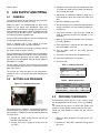
1 SAFETY
1.1 SAFETY LABELING AND
WARNING SIGNS
The words DANGER, WARNING and CAUTION
are used to identify the levels of seriousness
of certain hazards. It is important that
you understand their meaning. You will
notice these words in the manual as follows:
DANGER
Immediate hazards which WILL result in death or
serious bodily and/or material damage.
WARNING
Hazards or unsafe practices which CAN result in
death or serious bodily and /or material damage.
CAUTION
Hazards or unsafe practices which CAN result in
minor bodily and /or material damage.
1.2 IMPORTANT INFORMATION
WARNING
Non-observance of the safety regulations
outlined in this manual will potentially lead to
consequences resulting in death, serious bodily
injury and/or property damage.
WARNING
Installation and repairs performed by unqualified
persons can result in hazards to them and to
others. Installations must conform to local codes
or, in the absence of such codes, to codes of the
country having jurisdiction.
The information contained in this manual is
intended for use by a qualified technician, familiar
with safety procedures and who is equipped with
the proper tools and test instruments.
Failure to carefully read and follow all instructions
in this manual can result in death, bodily injury
and/or property damage.
1. It is the homeowner’s responsibility to engage
a qualified technician for the installation and
subsequent servicing of this furnace;
2. Do not use this furnace if any part of it was
under water. Call a qualified service technician
immediately to assess the damage and to replace
all critical parts that were in contact with water;
3. Do not store gasoline or any other flammable
substances, such as paper or carton, near the
furnace;
4. Do not stack items or boxing within the required
clearances to combustible materials specified in
Table 2;
5. Never block or otherwise obstruct the filter and/or
return air openings;
6. Ask the technician installing your furnace to show
and explain to you the following items:
• The main disconnect switch or circuit breaker;
• The gas shut off valve;
• The air filter and how to change it (at least
twice a year);
7. Before calling for service, be sure to have the
information of section 10 of your manual close by in
order to be able to provide the contractor with the
required information, such as the model and serial
numbers of the furnace.
WARNING
Failure to follow this warning could result in
dangerous operation, personal injury, death,
or property dammage. Improper installation,
adjustement, servicing or repair can cause carbon
monoxide poisoning, explosion, fire, electrical
shock, or other conditions which may cause
personal injury or property damage. Consult a
qualified service agency, local gas supplier, or
your distributor for information or assistance. The
qualified service agency must use only factory
authorized and listed kits or accessories when
modifying this product.
WARNING
INJURY HAZARD
Ignoring this warning could result in personal
injury.
Sheet metal parts may have sharp edges or burrs.
Use care and wear appropriate protective clothing,
safety glasses and gloves when handling parts,
and servicing furnaces
4

1.3 SAFETY CONSIDERATION
Untrained personnel can perform basic maintenance
functions such as cleaning and replacing air filters. All
other operations must be performed by trained service
personnel. When working on heating equipement,
observe precautions in literature, on tags, and on labels
attached to or shipped with the furnace. Other safety
precautions may apply.
These instructions cover minimum requirements and
conform to existing national standards and safety codes.
In some instances, these instructions exceed certain
local codes and ordinances, especially those that may
not have kept up with changing residential construction
practices. We require these instructions as a minimum
for a safe installation.
Follow all safety codes. Wear safety glasses, protective
clothing and work gloves. Have a fire extinguisher
available. Read these instructions thoroughly and follow
all warnings or cautions included in the literature and
attached to the unit.
1. Use only with type of gas approved for this furnace.
Refer to the furnace rating plate and section 5 :
GAS SUPPLY AND PIPING.
2. Install this furnace only in a location and position as
specified in section 3 : INSTALLATION.
3. Provide adequate combustion and ventilation air to
the furnace as specified in section 7 : VENTING
AND COMBUSTION AIR PIPING.
4. Combustion products must be discharged
outdoors. Connect this furnace to an approved vent
system only, as specified in section 7 : VENTING
AND COMBUSTION AIR PIPING.
5. Never test for gas leaks with an open flame.
Use a commercially available soap solution made
specifically for the detection of leaks to check
all connections, as specified in section 5 : GAS
SUPPLY AND PIPING.
6. Always install furnace to operate within the
furnace’s intended temperature-rise range with a
duct system which has an external static pressure
within the allowable range, as specified in section
4 : DUCT INSTALLATION of these instructions.
See furnace rating plate.
7. When a furnace is installed so that supply ducts
carry air circulated by the furnace to areas outside
the space containing the furnace, the return air
shall also be handled by duct(s) sealed to the
furnace casing and terminating outside the space
containing the furnace. See section 4 : DUCT
INSTALLATION.
This furnace may be installed, with a two pipe
sealed combustion configuration, in a space
utilized as part of the return air supply. A filter
must be installed at the return opening of the
furnace and a grill should be installed in the
space to allow proper circulation of air.
8. Gas furnace manufactured on or after May 1, 2017
are not permitted to be used in Canada for heating
of buildings or structures under construction.
9. A gas-fired furnace for installation in a residential
garage must be installed as specified in the
WARNING box below:
WARNING
FIRE, INJURY OR DEATH HAZARD
Failure to follow this warning could result in
personal injury, death and/or property damage.
When the furnace is installed in a residential
garage, the burners and ignitions sources must be
located at least 18 in. (457 mm) above the floor.
The furnace must be located or protected to avoid
damage by vehicles. When the furnace is installed
in a public garage, airplane hangar, or other
building having a hazardous atmosphere, the
furnace must be installed in accordance with the
NFPA 54/ANSI Z223.1-2009 or CAN/CSA B149.2-
2010.
Do not install the furnace on its back or
hang furnace with control compartment facing
downward. Safety control operation will be
adversely affected. Never connect return air duct
to the back of the furnace.
WARNING
ELECTRICAL SHOCK, FIRE OR EXPLOSION
HAZARD
Improper servicing could result in dangerous
operation, serious injury, death or property
damage.
-Before servicing, disconnect all electrical power
to furnace.
-When servicing controls, label all wires prior to
disconneting. Reconnect wires correctly.
-Verify proper operation after servicing.
WARNING
CARBON MONOXIDE POISONING HAZARD
Failure to follow this warning could result in
personal injury or death. The operation of
exhaust fans, kitchen ventilation fans, clothes
dryers, attic exhaust fans or fireplaces could
create a NEGATIVE PRESSURE CONDITION at the
furnace. Make-up air MUST be provided for the
ventilation devices, in addition to that required by
the furnace.
5

WARNING
CARBON MONOXIDE POISONING HAZARD
Failure to follow the steps outlined below for
each appliance connected to the venting system
being placed into operation could result in carbon
monoxide poisoning or death. The following steps
shall be followed for each appliance connected to
the venting system being placed into operation,
while all other appliances connected to the
venting system are not in operation:
1. Seal any unused openings in venting
system;
2. Inspect the venting system for proper
size and horizontal pitch, as required
in the National Fuel Gas Code, ANSI
Z223.1/NFPA 54 or the Natural Gas and
Propane Installation Code, CSA B149.1 and
these instructions. Determine that there
is no blockage or restriction, leakage,
corrosion and other deficiencies which could
cause an unsafe condition;
3. As far as practical, close all building doors
and windows and all doors between the
space in which the appliance(s) connected
to the venting system are located and other
spaces of the building;
4. Close fireplace dampers;
5. Turn on clothes dryers and any appliance not
connected to the venting system. Turn on
any exhaust fans, such as range hoods and
bathroom exhausts, so they are operating at
maximum speed. Do not operate a summer
exhaust fan;
6. Follow the lighting instructions. Place the
appliance being inspected into operation.
Adjust the thermostat so appliance is
operating continuously;
7. Test for spillage from draft hood equipped
appliances at the draft hood relief opening
after 5 minutes of main burner operation.
Use the flame of a match or candle;
8. If improper venting is observed during any
of the above tests, the venting system must
be corrected in accordance with the National
Fuel Gas Code, ANSI Z223.1/NFPA 54 and/or
Natural Gas and Propane Installation code,
CSA B149.1;
9. After it has been determined that each
appliance connected to the venting system
properly vents when tested as outlined
above, return doors, windows, exhaust
fans, fireplace dampers and any other gas-
fired burning appliance to their previous
conditions of use;
1.4 DETECTION SYSTEMS
It is recommended that carbon monoxide detectors be
installed wherever oil or gas fired heaters are used.
Carbon monoxide can cause bodily harm or death.
For this reason, agency approved carbon monoxide
detectors should be installed in your residence and
properly maintained to warn of dangerously high carbon
monoxide levels.
Also, the house should be equipped with approved and
properly maintained fire extinguishers.
Your unit is equipped with safety devices that can prevent
it from functioning when anomalies are detected such as
a blocked venting system.
1.5 DANGER OF FREEZING
CAUTION
FROZEN AND BURST WATER PIPE HAZARD
Failure to protect against the risk of freezing may
result in property damage. Special precautions
MUST be made if installing furnace in an area
which may drop below freezing. This can cause
improper operation or damage to equipment. If
furnace environment has the potential of freezing,
the drain trap and drain line must be protected.
CAUTION
PROPERTY DAMAGE HAZARD
Failure to follow this caution may result in
burst water pipes and/or property damage. If
a condensate pump is installed, a clogged
condensate drain or a failed pump may cause
the furnace to shut down. Do not leave the
home unattended during freezing weather without
turning off water supply and draining water pipes
or otherwise protecting against the risk of frozen
pipes.
Ensure all condensate drain connections are
secured and liquid tight. Use the furnished tube
clamps and verify tightness
6

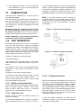
2 INTRODUCTION
This multiposition Category IV condensing furnace is
CSA design certified direct vent (2 pipes) and non-direct
vent (1 pipe). The furnace is factory shipped for use with
natural gas. The furnace can be converted in the field
for use with propane gas when a conversion kit is used
(B40574-03)
This furnace is designed for minimum continuous return
air temperature of 60 °F (16 °C) or intermittent operation
down to 55 °F (13 °C) such as when used with a night
setback thermostat. Return air temperature must not
exceed 80 °F (27 °C). Failure to follow these return
air temperature limits may affect reliability of heat
exchangers, motors, and controls.
2.1 CODES AND STANDARDS
Follow all national and local codes and standards in
addition to these instructions. The installation must
comply with regulations of the serving gas supplier, local
building, heating, plumbing, and other codes. In absence
of local codes, the installation must comply with the
national codes listed below and all authorities having
jurisdiction. In the United States and Canada, follow all
codes and standards for the following:
Table 1 – Codes and Standards
TOPIC USA CANADA
Safety National Fuel Gas
Code (NFGC) NFPA
54-2009/ANSI
Z223.1 and
the Installation
Standards, Warm
Air Heating and
Air Conditioning
Systems
ANSI/NFPA 90B
National Standard
of Canada, Natural
Gas and Propane
Installation Code
(NSCNGPIC)
CAN/CSA B149.1
General
installation
NFGC and the
NFPA 90B. For
copies, contact
the National
Fire Protection
Association Inc.,
Battery march
Park, Quincy, MA
02269; or for only
the NFGC contact
the American
Gas Association,
400 N. Capitol,
N.W.,Washington
DC 20001
NSCNGPIC. For
a copy, contact
Standard Sales,
CSA International,
178 Rexdale
Boulevard,
Etobicoke (Toronto),
Ontario, M9W 1R3,
Canada
Combustion
and and air
ventilation
Section 9.3 of
the NFPA54/ANSI
Z223.1 Air for
Combustion and
Ventilation
Part 8 of the
CAN/CSA B149.1,
Venting Systems
and Air Supply for
Appliances
Duct systems Air Conditioning Contractors Association
(ACCA) (Manual D), Sheet Metal and
Air Conditioning Contractors National
Association (SMACNA), or American
Society of Heating, Refrigeration, and
Air Conditioning Engineers (ASHRAE).
Acoustical
lining and
fibrous glass
duct
current edition of SMACNA, NFPA 90B
as tested by UL Standard 181 for Class I
Rigid Air Ducts.
Gas piping and
pipe pressure
testing
NFPA 54/ANSI
Z223.1 NFGC;
Chapters 5, 6, 7,
and 8 and national
plumbing codes.
CAN/CSA-B149.1,
Part 6
Manufactured
Mobile
housing
Manufactured
Home Construction
and Safety
Standard, Title
24 CFR, Part 3280
or The Standard
for Manufactured
Home Installations
ANSI/NCS A225.1
Canadian Standard
for Series M92
Mobile Homes,
CAN/CSA Z240MH
Electrical
connections
National Electrical
Code (NEC)
ANSI/NFPA 70
Canadian Electrical
Code CSA C22.1
Venting Part 7, Venting
of equipment,
latest edition of the
National Fuel Gas
Code NPFA 54,
90A and 90B ANSI
Z223.1-
CAN/CSA-B149.1-
05 latest edition
7

2.2 ELECTROSTATIC DISCHARGE
CAUTION
FURNACE RELIABILITY HAZARD
Failure to follow this caution may result in unit
component damage. Electrostatic discharge can
affect electronic components. Take precautions
during furnace installation and servicing to
protect the furnace electronic control. These
precautions will help to avoid exposing the control
to electrostatic discharge by putting the furnace,
the controls, and the technician at the same
electrostatic potential.
2.3 LOCATION
This furnace must :
• Be installed so the electrical components are
protected from water;
• Not be installed directly on any combustible
material other than wood flooring;
• Be located close to the chimney or vent and
attached to an air distribution system. Refer to
section 7.
• Be provided ample space for servicing and
cleaning. Always comply with minimum clearances
shown in table 2 or on the furnace rating label.
• The furnace must be installed in a conditioned
space.
Place the unit so that proper venting can be achieved,
with a minimum number of elbows, in accordance with
the instructions in this manual. The furnace should be
located as close to the chimney (vertical venting) or to
the outside vent wall (horizontal venting) as possible.
2.3.1 Location relative to cooling
equipement
The cooling coil can either be installed in the supply air
duct or in the return air duct. If the coil is installed in the
supply air duct, it must be at a minimum of 6" over the
furnace primary heat exchanger.
Table 2 – Minimum clearance
Position Clearance in (mm)
Rear 0
Front 24 (610)
All sides of supply plenum 1 (25)
Right side 8 (204)
Other Sides 0
Vent 0
Top of furnace Chinook compact 0
3 INSTALLATION
The furnace is factory built for upflow position. When
installing the furnace in other orientation than the upflow
position, simply re-route the tubing accordingly with the
instructions provided in this section of the manual.
CAUTION
PROPERTY DAMAGE HAZARD
Failure to follow this caution may result in water
spillage and/or property damage.
For any position other than upflow, the
multiposition pressure switch must be connected
pneumatically to the condensate box and
electrically to the control to allow the furnace
to stop in the event of drain blockage.
CAUTION
FURNACE MALFUNCTIONING
Failure to follow this caution may result in furnace
malfunctioning
For any position other than upflow, the furnace
must be incline of at least 1°. Refer to the furnace
position section for more details.
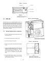
8

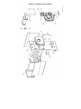
Figure 1 – Panel Identification
Figure 2 – Dimensions
9

Figure 3 – Top view
3.1 UPFLOW
The drain trap must be outside the furnace casing. Use
the 3 ports drain trap. The condensate drain hoses must
be routed to the trap through the furnace casing. Remove
the metal knock out on the side of the casing and route
the hoses to the drain trap. Refer to Figure 4. The drain
trap can be install to the side or the back of the panel.
Refer to figures 5 and 6 and choose which configuration
is better for the installation.
3.1.1 Uplow Condensate drain connection
1. Remove the appropriate drain trap knock out on the
furnace the casing.
2. Place the drain trap gasket on the drain trap.
3. Install the drain trap and its gasket
4. Screw in place the drain trap with two head tapping
screws
5. Connect the outlet drain from the drain trap to an
additional condensate piping using a ½” tee for an
adequate drainage of the condensate. DO NOT
vent using the remaining 3 outlet stubs. Such
a drain shall be in compliance with local building
codes.
6. Prime the drain trap with water. This will ensure
proper furnace drainage at startup and will avoid
any recirculation of flue gas.
Figure 4 – Upflow orientation
Figure 5 – Side drain trap
10

Figure 6 – Back drain trap
3.2 DOWNFLOW
When installing the furnace in Downflow orientation
you must incline the furnace of at least 1° to ensure
proper drainage of the condensate. Refer to figure 7
Make sure to allow enough space for inclination, venting
and drain trap.
3.2.1 Downflow Condensate drain
connection
1. Remove all PVC tubes from the ID blower,
condensate box and vent collector and block the
stub openings with furnished 1/2” black caps.
2. Use the furnished extra tubing and cut those 2
lengths : (1) 4.5" and (2) 9.25".
3. Remove the appropriate drain trap knock-out for
downflow orientation.
4. Cut open the pressure port, located on the
condensate box. See figure 8 for its location. It will
be connected to the multiposition pressure switch
in section 3.5.
5. Use the MULTIPOSTION DRAIN TRAP, which
has only two ports.
6. Place the drain trap gasket on drain trap.
7. Install the drain trap and screw in place with two
self-tapping screw to the furnace casing.
8. Reroute the condensate box drain tube to the drain
trap. Starting from condensate box use length (1)
4.5", a 90° elbow and length (2) 9.25"
9. Prime the drain trap with water. This will ensure
proper furnace drainage at startup and will avoid
any recirculation of flue gas.
10. Install one 1/2” black plastic caps on the remaining
stub of the drain trap.
11. Connect the outlet of drain trap to the condensate
drain piping with a tee. Such a drain shall be in
compliance with local building codes.
12. The venting must be drained using a PVC 636
tee. Connect this tee to a P-trap and connect it
to your condensate drain. Commercially available
condensate trap exist for use with IPEX system
636.
Figure 7 – Installation slope for downflow application
Figure 8 – Downflow condensate box pressure port
11

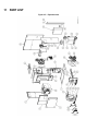
Figure 9 – Downflow installation detailed
3.3 HORIZONTAL
Horizontal application is perfect for ceiling installation.
Allow enough space for inclination of the furnace and
drain trap. Figure 10 will help you figure orientiation,
inclination and space needed.
When installing the furnace in horizontal orientation
you must tilt the furnace at least 0.5 in torward the
heat exchanger to ensure proper drainage of the
condensate. See figure 10
3.3.1 Horizontal Condensate drain
connection
1. Remove PVC tubes from the ID blower, condensate
box and vent collector and block the openings with
furnished ½” black caps.
2. Use the furnished extra tubing and cut those 4
lengths : (1) 3.75" , (2) 5.5" , (3) 5.5" and (4) 3.25".
3. Remove the appropriate knock-out for drain trap.
Refer to Figure 3, and look for horizontal drain trap
location.
4. Cut open the pressure port, located on the
condensate box behind the inducer. It will be
connected to the multiposition pressure switch in
section 3.5. For pressure port location see figure
12.
5. Use the MULTIPOSITION DRAIN TRAP, which
has only two ports.
6. Place the drain trap gasket on the drain trap.
7. Install the drain trap and screw in place with two
self-tapping screws to the furnace casing.
8. Reroute the ID blower drain tube from the ID blower
casing to the drain trap.
Starting from the ID blower use length (1)
3.75", 90° elbow and length (2) 5.5"
9. Reroute the condensate box drain tube from the
bottom of the condensate box to the drain trap.
Starting from the condensate box use length
(3) 5.5", 90° elbow and length (4) 3.25".
10. Prime the drain trap with water. This will ensure
proper furnace drainage at startup and will avoid
any recirculation of flue gas.
11. Connect the outlet of drain trap to the condensate
drain piping with a tee. Such a drain shall be in
compliance with local building codes.
12. The venting must be drained using a PVC 636
tee. Connect this tee to a P-trap and connect it
to your condensate drain. Commercially available
condensate trap exist for use with IPEX system
636. See figure 11.
3.4 VENTING DRAINAGE
All furnaces with horizontal exhaust vent piping must
have a PVC 636 drain tee assembly and trap installed
in the exhaust pipe as close to the furnace as possible.
3.5 MULTIPOSITION PRESSURE
SWITCH CONNECTION
The 3/16 stub just beside the drain of the condensate
box must be drilled or cut open. The black squared PVC
tubing of the multiposition pressure switch (-0.2 in w.c.)
must be connected to this stub. This tubing is furnished
with the furnace.
The pressure switch must now be electrically connected
in series with the low fire pressure switch (top) with the
brown jumper furnished in the part bag. See wiring
diagrams.
Figure 10 – Installation slope for horizontal
application
12

Figure 11 – Horizontal installation
Figure 12 – Horizontal installation detailed
13

4 DUCT INSTALLATION
4.1 GENERAL REQUIREMENTS
The duct system should be sized to handle the required
system design aiflow at the design external static
pressure. When a furnace is installed so that the supply
ducts carry air circulated by the furnace to areas outside
the space containing the furnace, the return air shall also
be handled by duct(s) sealed to the furnace casing and
terminating outside the space containing the furnace.
This furnace may be installed, with a two pipe sealed
combustion configuration (direct vent), in a space utilized
as part of the return air supply. A filter must be installed
in the return opening of the furnace and a grill should be
installed in the space to allow proper circulation of air.
Secure ductwork with proper fasteners for type of
ductwork used. Seal supply and return duct connections
to the furnace with code approved tape or duct sealer.
Ductwork passing through an unconditioned space
should be insulated to enhance system performance.
When air conditioning is used, a vapour barrier is
recommended.
Maintain a 1 in. (25 mm) clearance from combustible
materials to supply air ductwork for a distance of 36 in.
(914 mm) horizontally from the furnace. See NFPA 90B
or local code for further requirements.
Flexible connections can be used between ductwork and
furnace to prevent transmission of vibration.
Many states, provinces and localities are considering
or have implemented standards and/or restrictions on
duct sizing practices, ductwork leakage, and/or ductwork
thermal, airflow and electrical efficiencies. CONSULT
LOCAL CODE OFFICIALS for ductwork design and
performance requirement in your area.
4.2 DUCT EXTERNAL STATIC
PRESSURE
Higher than prescripted static pressure will decrease the
air flow, causing excessive temperature rise, opening of
the thermodisk, failure of the heat exchanger and / or
poor performance of the heat pump / air conditioning.
To measure total external static pressure, proceed as
follow:
1. Run the furnace at the system maximum airflow
2. Return duct : Make sure the furnace filter is clean
and measure the static pressure between the filter
and the inlet of the furnace (negative pressure
reading)
3. Supply duct : Measure the static pressure between
the furnace and the cooling coil (positive static
pressure). Tape up the hole when test is complete.
4. Substract the inlet pressure from the supply
pressure. For exemple, if you measured 0.3"w.c.
in the supply and -0.2" in the return:
0.3"w.c. - (-0.2"w.c.) = 0.5"w.c.
If the total external static pressure exceeds the maximum
listed on the furnace rating plate, check for closed
dampers, register, unproperly size duct work or incorrect
dipswitch settings. Make sure the temperature rise is
coherent with the furnace rating plate.
4.3 SMART DUCT SYSTEM
Dettson Industries also offers the Smart Duct System.
Please refer to the Smart Duct Manual (X40240) for
proper installation of this system.
Please note Smart Duct system can only be used with
approuved Smart Duct furnaces.
4.4 RETURN AIR CONNECTIONS
The return air duct must be connected to the bottom or
side. Knock-outs are available on the bottom, front side
and back side. Avoid front side, since it is the only panel
giving access to the blower and motor.
In downflow configuration, it must be connected to
bottom.
Static pressure in the return air duct should be -0.2"w.c.
at system maximum airflow.
4.5 SUPPLY AIR DUCTS
The supply air duct must be connected to the furnace
supply outlet air duct flanges. DO NOT cut furnace
casing to attach supply air duct, humidifier, or other
accessories. All accessories must be connected to the
supply or return ductwork, external to furnace’s casing.
It is recommend that the outlet duct be provided with
a removable access panel. This opening shall be
accessible when the furnace is installed and shall be
sized to allow the heat exchanger to be viewed or a probe
to be inserted for sampling the air stream. The cover
attachement should prevent leaks.
4.5.1 Ductwork acoutiscal treatment
Metal duct systems that do not have a 90 degree elbow
and 10 ft. (3 M) of main duct to the first branch
take-off may require internal acoustical lining. As an
alternative, fibrous ductwork may be used if constructed
and installed in accordance with the latest edition of
SMACNA construction standard on fibrous glass ducts.
Both acoustical lining and fibrous ductwork shall comply
with NFPA 90B as tested by UL Standard 181 for Class 1
14

Rigid air ducts.
5 GAS SUPPLY AND PIPING
5.1 GENERAL
Use a back-up wrench on the inlet of the gas valve when
connecting the gas line to the gas valve.
Report to Table 5 for recommended gas pipe sizing.
Support all gas piping with appropriate straps and
hangers. Use a minimum of 1 hanger every 6 ft (1.8 m).
Joint compound (pipe dope) should be applied sparingly
and only to male threads of joints. Pipe dope must be
resistant to the action of propane gas.
An accessible manual equipment shut off valve MUST be
installed external to furnace casing.
Install a sediment trap in riser leading to furnace.
Connect a capped nipple into lower end of tee.
Install a union between the manual shut off gas and the
gas valve in order to remove it easily.
Piping should be pressure and leak tested in accordance
with the current edition of the NFGC in the United States,
local, and national plumbing and gas codes before the
furnace has been connected. Refer to current edition of
NSCNGPIC in Canada.
The gas supply pressure shall be within the maximum
and minimum inlet supply pressures marked on the rating
plate and in Table 3.
The furnace gas valve inlet pressure tap connection is
suitable to use as test gauge connexion providing test
pressure.
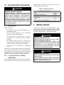
5.2 SETTING GAS PRESSURE
Figure 13 – Outlet pressure port
Gas outlet pressure should be set according to table 4.
A calibrated pressure gauge is required for gas pressure
measurements. Follow those steps to properly adjust the
servo gas valve :
1. Remove the square outlet pressure tap on the
manifold. Refer to figure 13.
2. Connect hose from a gauge to the pressure tap
(1/8" NPT).
3. Operate the unit to the flow rate mentioned in table
4. Installer can either use test mode (see table:16)
or t-stat fixed rate mode.
4. Adjustment or verification should be made on at
least two points, which are at flow rates 100% and
40%.
5. Note the manifold gas pressure.
6. To adjust the pressure, take off the regulator cap on
the gas valve and use a small slotted screwdriver in
the opening.
7. Only small variation in gas pressure should be
made by adjusting the pressure regulator (+/- 0.6
maximum)
8. Allow up to 20 seconds between each change to
the rotary dipswitch.
9. Once adjustment is made at 40% and 100% input,
turn off the power to the unit.
10. Turn the power back on, and verify pressure
adjustement.
11. Shut off the unit and replace the regulator cap.
12. Place the manifold pressure tap plug.
13. Check for leak.
Table 3 – Inlet Gas Pressure
Gas Pressure in.w.c. (psig)
Minimum Maximum
Natural
Gas
4.5 10.5
Propane 11.0 13.0
Table 4 – Outlet gas pressure
Gas Pressure in. w.c.
Input Natural Gas Propane
High fire (100%) 3.2 +/- 0.3 8.35 +/- 0.5
Low fire (40%) 0.8 +/- 0.3 2.09 +/- 0.3
5.3 PROPANE CONVERSION
To convert from natural gas to L.P. gas, installer should
use the appropriate conversion kit, in this case B40574-
03.
The conversion kit consist an orifice #56, jumper and
stickers to clearly identify conversion on the gas valve.
Follow the steps bellow to convert the gas valve to
propane :
1. Move the switch located on the valve to the «off»
position.
2. Remove the «NAT. GAS» label from the top of the
gas valve.
15

3. Using a pair of tweezers or needle nose pliers,
place the jumper (supplied) on the receptacle
located beneath the label that was removed in step
2. Use care to make sure that both prongs of
receptacle engage the jumper.
4. Place the «LP» label (supplied with the kit) on the
gas valve over the opening to the jumper.
5. Attach the “WARNING” label (supplied with this kit)
to the gas valve where it can readily be seen.
6. Move the switch located on gas valve back to the
“ON” position.
7. Unscrew the manifold.
8. Replace the natural gas burner orifices with the LP
orifice (# 56) supplied with the kit.
9. Replace the manifold and make sure it’s properly
aligned with the burners.
10. Make sure the gas valve outlet pressure (measured
on the outlet pressure tap) is compliant with the
outlet pressure. Outlet pressure is specified in table
4 and on the nameplate of the furnace.
5.4 GAS PIPE GROMMET
For direct vent applications, the hole for the gas pipe on
the cabinet must be sealed to prevent air leakage. Install
the grommet in the hole, then insert the gas pipe.
Table 5 – Maximum capacity of pipe Cu.ft./Hr for pipe length ft (m)
Nominal Iron pipe size in. (mm) Internal dia. in. (mm) 10 (3.0) 20 (6.0) 30 (9.1) 40 (12.1) 50 (15.2)
1/2 (13) 0.622 (158) 175 120 97 82 73
3/4(19) 0.824 (20.9) 360 250 200 170 151
1 (25) 1.049 (26.6) 680 465 375 320 285
1-1/4 (32) 1.380 (35.0) 1400 950 770 660 580
1-1/2 (39) 1.610 (40.9) 2100 1460 1180 990 900
6 ELECTRICAL CONNECTION
6.1 120V WIRING
Furnace must have a 120 V power supply properly
connected and grounded. Proper polarity must be
maintained for 120 V wiring. If polarity is incorrect,
furnace will NOT operate. Verify that the voltage,
frequency, and phase correspond to that specified on
unit rating plate. Also, check to be sure that service
provided by utility is sufficient to handle load imposed
by this equipment. Use a separate fused branch
electrical circuit with a properly sized fuse or circuit
breaker for this furnace. A readily accessible means of
electrical disconnect must be located within sight of the
furnace.Refer to rating plate or Table 8.
6.2 THERMOSTAT/24V Wiring
6.2.1 Non-communicating, one-stage or
two-stage thermostat
NOTE: Do not use 24 volt control wire smaller than No.
18 AWG.
Wire all non-communicating thermostats to the 24V
connections on the integrated furnace control.
NOTE: A larger wire gage may be required for longer
lengths of thermostat wire.
Operations with a non-communicating thermostat (one-
stage or two-stage) are not fully modulating. See table 7
for configuration details.
Operation with a 2-stage thermostat requires dispwitch
configuration (see table 7) and will proceed as follow : call
on W1 will result in a 40% input, call on W2 will resulat
in 60% input for 6 minutes followed by 100% input until
thermostat demand is satisfied.
Operation with a single stage thermostat will operate in
three phase, as describe in table 6 below.
Table 6 – OPERATION WITH SINGLE STAGE T-STAT
PHASE TIME INPUT
PHASE 1 0-5 minutes 40%
PHASE 2 5-12 minutes 60%
PHASE 3 12 + 100%
Table 7 – THERMOSTAT TYPE SELECTION
S4-2 S4-3 DESCRIPTION
OFF OFF Modulating, communicating or 1-stage t-stat
ON OFF 40% TEST MODE
OFF ON 100% TEST MODE
ON ON 2-STAGE T-STAT
6.2.2 Communicating thermostat
This furnace is capable of communicating with a
thermostat and heat pump. Installation of the
communicating thermostat allow full modulation of the
furnace and heat pump. Connections of the thermostat
must be made at the furnace control.
16

6.3 ALTERNATE POWER SUPPLY
Dettson doesn’t recommend to operate the furnace on a
generator or other alternate power supply. If so it must
produce a smooth sinusoidal waveform for compatibility
with the furnace electronics. The alternate power supply
must generate the same voltage, phase, and frequency
(Hz) as shown on the furnace rating plate.
Power from an alternate power supply that is non-
sinusoidal may damage the furnace electronics or cause
erratic operation.
Contact the alternate power supply manufacturer for
specifications and details.
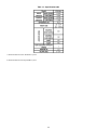
Table 8 – Electrical Data
Unit size Volts-Hertz-Phase Operating Operating Maximum Unit Maximum fuse
range Min range Max unit amp ampacity CKT BRK amp
15,000 120-60-1 127 104 10.7 12.6 15
17

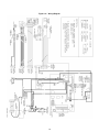
Figure 14 – Wiring Diagram
18

7 VENTING AND COMBUSTION
AIR PIPING
WARNING
CARBON-MONOXIDE POISONING HAZARD
Failure to follow instruction could result in severe
personal injury or death due to carbon-monoxide
poisoning, if combustion products infiltrate into
the building.Check that all openings in the outside
wall around the vent (and air intake) pipe(s)
are sealed to prevent infiltration of combustion
products into the building.Check that furnace vent
(and air intake) terminals are not obstructed in
any way during all seasons.
WARNING
Corrosive or contaminated air may cause failure
of parts containing flue gas, which could leak into
the living space. Air for combustion must not
be contaminated by halogen compounds, which
include fluoride, chloride, bromide and iodide.
These elements can corrode the heat exchanger
and burner cabinet component. This conditions
would shorten the furnace life. Air contaminants
are found in aerosol sprays, detergents, bleaches,
cleaning solvents, salts, air fresheners, and other
household products. Do not install the furnace
in a corrosive or contaminated atmosphere.
Make sure all combustion and circulating air
requirements are met, in addition to all local codes
and ordinances.
7.1 GENERAL
If this furnace replaces a furnace that was connected to
a vent system or chimney, the vent or vent connectors
of other remaining appliances may need to be re-sized.
Vent systems or vent connectors of other appliance must
be sized to the minimum size allowable.
An abandoned masonry chimney may be used as
a raceway for properly insulated and supported
combustion-air (when applicable) and vent pipes. Each
furnace must have its own set of combustion air and vent
pipes.
A furnace shall not be connected to a chimney flue
serving a separate appliance designed to burn solid fuel.
Other gas appliances with their own venting system
may also use the abandoned chimney as a raceway
providing it is permitted by local code, the current edition
of the National Fuel Gas Code, and the vent or liner
manufacturer’s installation instructions. Care must be
taken to prevent the exhaust gases from one appliance
from contaminating the combustion air of other gas
appliances.
• The vent pipe and combustion air pipe must be the
same diameter.
• Slope horizontal vent piping upward a minimum
of 1/4" per foot of run so that condensate drains
toward the furnace.
• Support horizontal vent piping at least every five
feet. No sags or dips are permitted
• The vent pipe and combustion air pipe must
terminate on the same building side.
• Installation of self regulating 5 or 7 watt heating
cable at the termination of venting could be a
necessity if ice build up is expected. See section
7.2.
7.2 VENT/EXHAUST BLOCKAGE
DUE TO ICE BUILD UP
WARNING
If outdoor design conditions are -8°F (-22°C) or
less and furnace maximum input is equal or lower
than 45 000 BTU/hr, there is a high risk of ice
blockage at the vent termination. Provision for
heating cable at the exhaust should be made
to avoid furnace shut down at the most critical
temperatures.
If your furnace has a maximum input of 45 000 BTU/hr
and if design outdoor conditions are –8°F (-22°C) or
less, this section should be thoroughly considered before
final installation of the furnace. Dettson is proud to offer
one of the most efficient furnaces (+97% AFUE) on the
market as well as being the only supplier of perfectly
sized furnace in terms of footprint and input. The
energy supplied to the furnace is delivered throughout
the home for the comfort of the occupant rather than
outside. In these installations, residual energy in the
chimney/vent are minimized and flue gases are expelled
at low velocity. In some weather conditions, it leads to
condensate freeze up at the termination and the furnace
shuts down because of the ice blockage. To prevent
this phenomenon, Dettson highly suggests installing 5-
watt/ft or 7-watt/ft self-regulating heating cable at the
termination, inside of the pipe. Heating cable must be UL
listed. Dettson recommends installing cable as per figure
15. In the figure, straight venting termination is depicted,
but the insertion pattern remains for eiter of the permitted
termination.
19

Figure 15 – Suggested heating cable insertion in vent
termination
7.3 DIRECT VENT
When this furnace is installed as a direct vent (2 pipes)
furnace, no special provisions for combustion air are
required.
Direct vent installations require a dedicated combustion
air and exhaust vent piping. The system is only using
outside air for combution.
The vent and combustion air pipe can terminate vertically,
through the roof or horizontaly through and outside wall.
Refer to figures for approved termination.
Penetration throught a roof requires appropriate sealing
and proper flashing.
In Canada, refer to manufacturer’s instructions for
supporting ULC S636 venting. ABS can be used for the
combustion air pipe.
7.4 NON DIRECT VENT
All air for combustion comes directly to the furnace from a
space that is well ventilated with outdoor air (such as an
attic or crawlspace). In addition, other gas appliances
installed in the space with the furnace may require
outside air for combustion. The combustion air pipe
cannot be terminated in attics or crawlspaces that uses
ventilation fans designed to operate during the heating
season. If ventilation fans are present in these areas, the
combustion pipe must terminate outdoors as a direct vent
(2 pipe) system.
7.5 SPECIAL VENTING
REQUIREMENTS FOR
INSTALLATION IN CANADA
In Canada, S636 certified primers and cements must
be used and be of the same manufacturer of the S636
venting system- do not mix primers and cements from
one manufacturer with a vent system from a different
manufacturer. Follow the manufacturer’s instructions in
the use of primer and cement and never use primer or
cement beyond its expiration date.
All fire stop and roof flashing used with this system must
be UL listed material.
Acceptability under Canadian standard CAN/CSA B149
requires full compliance with all installation instructions.
The authority having jurisdiction (gas inspection
authority, municipal building department, fire department,
etc.) should be consulted before installation to determine
the need to obtain a permit.
7.6 MATERIAL
USA:
Combustion air and vent pipe, fittings, primers and
solvents must conform to American National Standard
Institute (ANSI) and American Society for Testing and
Material (ASTM) and be of the same manufacturer. See
table 9
Table 9 – Approved Vent and Combustion air pipe
material USA installation
Material Standards
PVC - DWV ANSI/ASTM D2265
PVC schedule 40 ANSI/ASTM D1785
CPVC Schedule 40 ANSI/ASTM F441
SDR-21, SDR-26-26 PVC ANSI/ASTM D2241
ABS-DWV Schedule 40 ANSI/ASTM D2661
Stainless steel (SS) UL-1738
Polypropylene (PP) UL-1738 and ULC-
S636
All vent piping and combustion air piping MUST
conform to local and national codes.
Pipe cement must be PVC (ANSI/ASTM D2564) or
CPVC (ANSI/ASTM F493).
Primers must be PVC/CPVC (ANSI/ASTM F656).
CANADA:
Vent pipe installations in Canada must conform to
the requirements of CAN/CSA B149 code. PVC and
CPVC vent systems must be composed of pipe, fittings,
cements, and primers listed to ULC S636 and must be of
the same manufacturer.
Combustion air pipe can use ABS material meeting the
ASTM standard D2661 / CSA B181.1.
All vent piping and combustion air piping MUST conform
to local and national codes.
7.7 SIZE DE VENT AND
COMBUSTION AIR PIPES
Furnace combustion air and vent pipe connections are
sized for 2” pipe.
The maximum allowable vent length for the vent and
combustion air pipe (when used) is listed in table 10
20
Page is loading ...
Page is loading ...
Page is loading ...
Page is loading ...
Page is loading ...
Page is loading ...
Page is loading ...
Page is loading ...
Page is loading ...
Page is loading ...
Page is loading ...
Page is loading ...
Page is loading ...
Page is loading ...
Page is loading ...
Page is loading ...
-
 1
1
-
 2
2
-
 3
3
-
 4
4
-
 5
5
-
 6
6
-
 7
7
-
 8
8
-
 9
9
-
 10
10
-
 11
11
-
 12
12
-
 13
13
-
 14
14
-
 15
15
-
 16
16
-
 17
17
-
 18
18
-
 19
19
-
 20
20
-
 21
21
-
 22
22
-
 23
23
-
 24
24
-
 25
25
-
 26
26
-
 27
27
-
 28
28
-
 29
29
-
 30
30
-
 31
31
-
 32
32
-
 33
33
-
 34
34
-
 35
35
-
 36
36


Dettson Chinook Compact Installation guide
- Type
- Installation guide
Ask a question and I''ll find the answer in the document
Finding information in a document is now easier with AI