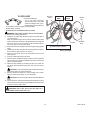
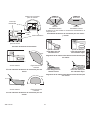
Heath Zenith 598-1116-10 Owner's manual
- Category
- Motion detectors
- Type
- Owner's manual
This manual is also suitable for

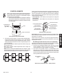
ON
1 2 3
4
ON
1 2 3
4
ON
1 2 3
4
ON
1 2 3
4
ON
1 2 3
4
ON
1 2 3
4
ENGLISH
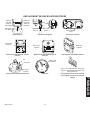
Remote Controlled Products
This manual includes operating instructions for a variety of remote controlled products. All products work on the same principle and use the same
code setting information. Please read all instructional information and note any specific information pertaining to your particular product.
WARNINGS:
• FOR USE ONLY with 120 volt incandescent or halogen bulbs.
• DO NOT USE with fluorescent bulbs, appliances, power supplies, low voltage lighting, or any other electrical devices.
• Transmitters
– Remote Control
– Add-A-Switch
– Entry Switch
– Indoor Wireless Motion Sensor
– Outdoor Wireless Motion Sensor
• Receivers
– Indoor Plug-In Converter
– Lamp Socket Converter
– Floodlight
This manual applies to the following products:
FEATURES
• Products are UL/cUL and/or FCC/IC tested and approved.
• Operational range of up to 100 feet.
Heath
®
/Zenith wireless lighting controls are designed to
work together. Simply determine which transmitter(s) you
would like to have control which receiver(s) and set the code
setting to match.
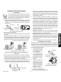
CODE SETTINGS
Note: Most single system installations will not require any
change to the code setting. Transmitter(s) and receiver(s)
must have the same code and group setting to work together.
Switches 1 through 3 set the code. Switch 4 sets the Group
(A or B). See page 2 for switch locations.
DIM
ON
OFF
ON
OFF
DIM
Receiver(s)
Code
Transmitter(s)/
Receiver(s) Code
Group “A”
Group “B”
Remote Motion
Sensor Code
Group “A”
Example 1 - Code Settings, System 1
(Factory Setting)
Left Side Controls:
Controls One Set of
Group “A” or Group
“B” Receiver(s)
Right Side Controls:
Controls One Set of
Group “A” or Group
“B” Receiver(s)
Transmitter(s)/
Receiver(s) Code
Group “A”
Example 3 - Code Settings with Single Transmitter
When using a single group transmitter (i.e. Door Transmitter, Add-A-
Switch, Remote Motion Sensor) the code and group settings must
match receiver(s) for the system to function properly.
Note: This setting will work independently of examples 1 and 2
because the code setting is different.
Note: The code can also be changed to reduce interference problems
from other wireless products (i.e. wireless phones, garage door open
-
ers, etc.). See Troubleshooting Guide for more information.
( – Indicates Position of Switch)
Example 2 - Code Settings, System 2
Note: When operating more than one system independently of each
other, set each system to a different code. There are 8 codes avail-
able by changing the settings of switches 1 through 3.
Receiver(s)
Code
Group “A”
Transmitter
Code
Group Switch
(Group “A” Selection Shown)
© 2006 DESA Specialty Products™ 598-1116-09

2 598-1116-09
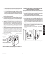
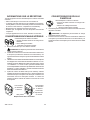
Indoor Plug-In Converter
CODE SWITCH LOCATIONS
O
N
1
2 3
4
Code
Switches
1 2 3 4
ON
2032
3
V
L
i
t
h
i
u
m
B
a
t
t
e
r
y
DIM
Add-A-Switch
Access
Door
1 2 3 4
ON
2032
3
V
L
i
t
h
i
u
m
B
a
t
t
e
r
y
DIM
Entry Switch
FloodlightLamp Socket Converter
1
2 3
4
Code
Switches
Screw
Cover
Code
Switches
Outdoor Wireless Motion Sensor
Code
Switches
DE TEC T
CO DES
1 2 3 4
DA
Y
NI GHT
NI GHT
ON L
Y
Code
Switches
ON
1 2 3
4
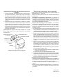
Close-Up of Typical Code Switch
(Factory Default Setting is Off)
Note: The “X” has been placed on the
switches to help clarify the code settings
on the previous page.
CR2032
3 VOLTS
1 2 3 4
ON
Code Switches
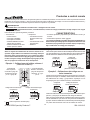
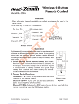
Remote Control
ON DIP
1 2 3 4
ON DIP
1 2 3 4
Right Side
Code
Switches
Battery
Cover
Left Side
Code
Switches
Indoor Wireless Motion Sensor
Code
Switches
CODE
1 2 3
4
ON
5 1 T EST
ON-TIME
(MINUTES)
MIN MAX
DETECT
RANGE
DAY
NIG HT
NIG HT
ONLY

3598-1116-09
ENGLISH
Note: One remote control is able to independently oper-
ate two receiver units. If more than two receiver units,
operating independently, are desired, additional remote
controls will need to be purchased.
1. Remove Tab from Battery Chamber. Remove cover
from back of transmitter. Gently pull tab out of battery
chamber. Slide cover onto transmitter.
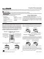
REMOTE CONTROL
Rear View of Remote Control
4 5 43
1 2 3
2
2. Remote Control Functions. The three buttons on the left side
of the remote will operate one or more receiver units with
matching code settings. The three buttons on the right side of
the remote will operate a second set of one or more receiver
units.
• ON: Turns on any receiver unit set to the same code as this
remote control.
• OFF: Turns off any receiver unit set to the same code as this
remote control.
• DIM: Activates the DIM feature for any receiver unit set to the
same code as this remote control. Note: Pressing the DIM button
steps through five brightness levels.
ON DIP
1 2 3 4
ON DIP
1 2 3 4
Battery Chamber
(Type A23)
Battery
Cover
Tab
Note: To independently operate a second receiver unit using a
single remote control, make sure the second set of code switches
(Right Side) and the code switches on each receiver match (see
Code Settings section).
• Left Side - Set left side code switches.
• Right Side - Set right side code switches.
Important: Wait 1 to 2 seconds after you press a transmitter
button before you press it again to allow the transmission to be
completed.
Note: If light does not turn on or intermittently turns on and off when
transmitter buttons are pushed, see Troubleshooting Guide.
Optional Car Visor Clip (Included)
The remote control includes an optional car visor clip for added
convenience that may be installed.
1. To attach car visor clip to remote control (if desired) push it
into slot on rear of remote unit until it snaps into place.
2. To remove car visor clip, insert a small, flat-head screwdriver
into slot on back of remote. Gently push down on portion of
visor clip inside slot with screwdriver while pulling clip out of
remote from top.
Removing Visor Clip - Rear View
Flat-Head
Screwdriver
Optional
Visor Clip
Function Controls
Left Side DIM
Left Side ON
Left Side OFF
Right Side DIM
Right Side ON
Right Side OFF

4 598-1116-09
5. Continue to press the DIM button until the desired dim level is
reached. Note: Receiver remembers last DIM setting used. To
recall last DIM setting, push and release the DIM button.
Note: The DIM setting defaults to 50% in the event of a power
failure.
Important: Wait 1 to 2 seconds after you press a transmitter
button before you press it again to allow the transmission to be
completed.
Note: If light does not turn on or intermittently turns on and off when
transmitter buttons are pushed, see Troubleshooting Guide.
Battery Replacement
The wall switch transmitter requires a type CR2032, 3-volt lithium
battery to operate. The transmitter is shipped with the battery
installed. With typical use, the battery will last approximately 5
years. Remove battery when transmitter will not be used for an
extended period of time.
1. Place thumb on access door
and slide down to open.
2. Carefully bend locking tab
outward. Battery will pop
up.
3. Remove battery from sock-
et.
4. Install replacement battery in
socket plus (+) side up (see
illustration). Press down on
battery until locking tab snaps
into place.
5. Reinstall access door by
sliding it upward until it locks
in place.
ADD-A-SWITCH
Installation
1. Remove Tab from Battery Chamber. Remove cover
from front of Add-A-Switch transmitter. Gently pull tab
out of battery chamber. Slide cover onto Add-A-Switch
transmitter.
D
IM
Add-A-Switch
Add-A-Switch
ON/OFF
Button
DIM
Button
Access Door
D
IM
Removing Battery Tab
1 2 3 4
ON
2032
3
V
L
i
t
h
i
u
m
B
a
t
t
e
r
y
DIM
Battery Chamber
(Type CR2032)
Access Door
Tab
1 2 3 4
ON
DIM
2032
3
V
L
i
t
h
i
u
m
B
a
t
t
e
r
y
CR2032
Lithium
Battery
Battery
Locking
Tab
Access
Door
Removing Access Door
and Battery
2. Select mounting location for add-a-switch transmitter. Note: Trans
-
mitter should be located within 100 feet (30 m) of receiver.
Note: Transmitter should be mounted approximately 4 feet
from the floor and in the vertical position.
3. Before mounting, hold transmitter in selected location and
verify operation (see Operation). Note: If transmitter does not
operate correctly, see Troubleshooting Guide.
4. With transmitter held in place, mark the mounting holes with
a pencil or pointed object.
5. Remove transmitter and drill two 3/16” holes. Tap drywall
anchors (provided) into holes with a hammer.
6. Attach transmitter to wall using two screws (provided).
Operation
1. Verify that receiver has been properly installed. See Receiver
Information, page 7.
2. Push the ON (top) button and release. The light should turn
on full bright.
3. Push the OFF (bottom) button and release. The light should
turn off.
4. Push the DIM button and release. The light should turn on at
a DIM level.

5598-1116-09
ENGLISH
ENTRY SWITCH
Installation
Note: Entry system includes a transmitter and magnet. The system
can be used to signal that a door or window has been
opened or to automatically turn the light on when
entering a closet, attic, room, etc.
1. Remove Tab from Battery Chamber. Remove transmitter back
cover from transmitter using small, flat-blade screwdriver. Gently
pull tab out of battery chamber.
Removing Battery Tab
Important Considerations:
• Entry transmitter components are for indoor use only.
• The transmitter should be mounted on the frame of door or
window (stationary surface). The magnet should be mounted
on door or window (moving surface). See illustration below for
mounting configurations and possible directions of movement.
1 2 3 4
ON
CR2032
3 VOLTS
Battery (Type
CR2032)
Transmitter
Tab
Flat-Head
Screwdriver
Possible Directions
of Movement
Possible Directions
of Movement
Possible Directions
of Movement
Possible Directions
of Movement
• A compatible receiver must be used to complete the system. The
receiver should be located within 100 feet (30 m) of transmitter
(maximum distance may vary depending on type of structures
between transmitter and receiver).
2. Select mounting location for entry transmitter. Note: Maximum
gap between transmitter and magnet is 3/8” and the arrows
located on the face of each component must be in alignment
(see illustration). Also, the front surfaces of the transmitter
and magnet must be flush. If magnet is recessed, use magnet
extension and two long screws (provided) to ensure proper
alignment.
Transmitter Mounted On Stationary Surface
Magnet Mounted On Moving Surface
Mounting Configurations and Possible Directions of
Movement
3/8" MAXIMUM
3. Before mounting, hold transmitter and magnet in selected
location and verify operation. While holding the transmitter
stationary, move the magnet away from transmitter to simulate
door or window being opened. Verify red LED on transmitter
flashes momentarily and receiver turns light on. Return magnet
to original position simulating door or window being closed.
Verify red LED on transmitter flashes momentarily and receiver
turns light off. Note: If transmitter does not operate correctly,
see Troubleshooting Guide.
4. Mount Transmitter.
Screw Mounting: Attach transmitter back cover to wall using two
short screws (provided). Snap transmitter onto back cover.
Tape Mounting: Apply large piece of foam tape (provided)
to the transmitter back cover. Stick transmitter back cover to
frame of door or window in desired position. Snap transmitter
onto back cover.
5. Repeat step 4 to attach magnet to door or window.
Battery Replacement
The entry transmitter requires a type CR2032, 3-volt lithium
battery to operate. The transmitter is shipped with the battery
installed. With typical use, the battery will last approximately five
years. Remove battery when transmitter will not be used for an
extended period of time.
1. Remove transmitter from
transmitter back cover
using small, flat-blade
screwdriver.
2. Carefully pry battery
loose with small, flat-blade
screwdriver. Battery will
pop up.
3. Install replacement battery
in socket plus (+) side up
(see illustration). Press
down on battery until it
snaps into place.
4. Snap transmitter onto
back cover.
Note: The magnet does not
require a battery.
CR2032
3 VOLTS
1 2 3 4
ON
CR2032 Lithium Battery
Flat-Blade
Screwdriver
Battery Replacement
Transmitter
Possible Directions of
Movement
Possible Directions of
Movement

6 598-1116-09
DE TEC T
CO DES
1 2 3 4
DA
Y
NI GHT
NI GHT
ON L
Y
Detect
Control
Battery Compartment
INDOOR AND OUTDOOR
WIRELESS MOTION SENSOR
Features:
• No wiring required.
• Up to 30 feet sensing range, 150° Coverage
(Indoor).
• Up to 70 feet sensing range, 180° Coverage
(Outdoor).
• Adjustable sensitivity.
• Day/Night or Night only operation.
• Test mode.
• Uses 2 AA batteries.
• Can be mounted directly to wall or with
mounting bracket (included) (Indoor).
• Wall or eave mount (Outdoor).
• Controls receivers up to 100 feet away.
O
N
D
ay
/
Night
N
ight
Only
5 1
Te
s
t
M
ax
Mi
n
Outdoor Wireless
Motion Sensor
Indoor Wireless
Motion Sensor
CODE
1 2 3
4
ON
5 1 TE ST
ON-TIME
(MINUTES)
MIN MAX
DETECT
RANGE
DAY
NIGH T
NIGH T
ONL
Y
Outdoor Motion Sensor
(Rear View)
Indoor Motion Sensor
(Front View)
Select Night or 24 Hour Mode
These sensors are able to detect motion day and night or night
only. To set the detection mode, remove battery compartment
cover by sliding the cover down. Remove batteries if necessary.
Slide the DETECT switch to either the DAY/NIGHT or NIGHT
ONLY position. Replace battery compartment cover by reversing
the above instructions.
Installing Batteries
• Before mounting outdoor motion sensor, remove battery compart-
ment cover by sliding the cover down.
• For indoor motion sensor, install batteries after sensor is in-
stalled.
Install 2 AA batteries according to polarity markings inside the
battery compartment. Replace battery compartment cover by
reversing the above instructions.
Swivel
Ball
Mount
Ball Mounting
Bracket
Ball Mounting
Bracket Screw
Tab
Rear of Sensor
Tab Slots
Attaching Ball Mounting Bracket to Indoor Motion Sensor
(Vertical Installation Shown)
Installing Indoor Motion Sensor Using Optional
Mounting Bracket
Note: Mount the indoor motion sensor so that it can be angled up or
down to give you the desired coverage above the floor level.
1. Attach ball mounting bracket to rear of motion sensor. The ball
mounting bracket is designed to mount to the rear of the sensor
in three possible directions depending upon the installation
requirements. To attach the ball mounting bracket, follow the
steps shown below:
• Determine the best mounting position of the sensor for the
coverage desired.
• Determine the best location of the wall mounting bracket.
• Insert the tabs on the ball mounting bracket into the tab slots
on the rear of the sensor that best align the sensor with the
wall mounting bracket.
• Remove the batteries.
• Using a philips-head screwdriver, insert mounting screw into
the hole in the battery compartment that aligns with the hole
on the rear of the ball mounting bracket. Tighten securely.
2. Place sensor mounting bracket against surface to be mounted
on and mark hole locations with pencil or center punch.
3. Using a 2.5 mm (0.1”) drill bit, drill two pilot holes for mounting
screws. If not mounting directly to wood or wood stud, drill 5
mm (0.2”) pilot holes and use the included wall anchors.
4. Attach indoor motion sensor mounting bracket to a sturdy object
(i.e. wall, ceiling, post, etc.) using two screws provided. Make sure
unit has an unobstructed view. Note: Attach mounting bracket
vertically if connecting to a curved surface such as a post.
5. Install motion sensor to mounting bracket. Using a Philips-head
screwdriver, loosen the clamp screw on the mounting bracket.
Insert swivel ball mount on sensor into mounting bracket socket

7598-1116-09
ENGLISH
(Note: You should hear a snap). Aim sensor toward area where
detection is desired. Tighten clamp screw.
O
N
D
ay
/
N
ight
Night
Only
5 1 Te
s
t
M
ax
M
in
Attaching Indoor Motion Sensor to Mounting Bracket
Mounting
Bracket
Clamp
Screw
Nut
Sensor
Mounting Screw
Swivel Ball Mount
Battery Compartment
Cover
Installing Indoor Motion Sensor Directly To Wall
Note: Mount the indoor motion sensor so that it is approximately
between waist and shoulder level above the floor (Example: Level
with light switch, under counter top, etc.).
1. Determine the best mounting position of the sensor for the
coverage desired. Remove the batteries.
2. Place indoor motion sensor against surface to be mounted on.
Using two of the holes on the rear of the battery compartment,
mark hole locations with pencil or center punch.
3. Using a 2.5 mm (0.1”) drill bit, drill two pilot holes for mounting
screws. If not mounting directly to wood or wood stud, drill 5
mm (0.2”) pilot holes and use the included wall anchors.
4. Attach indoor motion sensor to a sturdy object (i.e. wall, cabinet,
post, etc.) using two screws provided. Make sure unit has an
unobstructed view.
IMPORTANT: Hand tighten only - do not overtighten.
O
N
D
ay /
N
ig
ht
N
ig
ht
O
nly
5 1 T
e
st
M
ax
M
in
O
N
D
ay /
N
i
ght
Night
O
n
ly
5 1 T
est
M
ax
M
in
O
N
D
ay /
N
ight
N
ight
O
nly
5 1 T
est
M
ax
M
in
O
N
D
ay /
N
ig
ht
N
ig
ht
O
nl
y
5 1 T
est
M
ax
M
in
Attaching Indoor Motion Sensor Directly to Wall
Mounting
Screw
Motion
Sensor
Counter
Top
Mounting
Bracket Socket
Continued
Installing Motion Sensor
Mounting Bracket
Clamp
Screw
Nut
Sensor
Mounting Screw
Swivel Ball Mount
Mounting
Bracket Socket
Installing Outdoor Motion Sensor
1. Install sensor mounting bracket where motion detection is desired.
Attach sensor mounting bracket to a sturdy object (i.e. tree, post,
house, etc.) using two screws provided. Make sure unit has an
unobstructed view. Note: Attach mounting bracket vertically if
connecting to a curved surface such as a post.
2. Install motion sensor to mounting bracket. Using a Philips-head
screwdriver, loosen the clamp screw on the mounting bracket.
Insert swivel ball mount on sensor into mounting bracket socket
(Note: You should hear a snap). Aim sensor toward area where
detection is desired. Tighten clamp screw.
IMPORTANT: The sensor must be mounted with the bottom cover
facing down in order to maintain water tightness.
Check Operation and Adjustment
Note: When first turned on or when switching modes wait 30
seconds.
Locate the RANGE control and ON-TIME control on the motion
sensor:
• Indoor Motion Sensor - The RANGE control and ON-TIME
control are located inside the battery compartment on the front
of the sensor. To set the RANGE or ON-TIME control, remove
battery compartment cover by sliding the cover down.
• Outdoor Motion Sensor - The RANGE control and ON-TIME control
are located on the bottom of the sensor. Using your fingernails or
a small, flat-head screwdriver, gently pry the cover until it opens.
1. Check Operation. Set the ON-TIME control to TEST mode. Walk in
front of sensor unit. The LED indicator light should flash when motion
is detected (see illustration, page 8, for location of LED light).
2. Adjust Sensor. Turn the RANGE control to the mid position
and ON-TIME control to the TEST position. Walk through
coverage area noting where you are when the LED begins to
flash. Loosen the clamp screw and move the sensor to change
the coverage area. Tighten clamp screw when finished. Do not
overtighten clamp screw.

8 598-1116-09
Maximum
Coverage Angle
Maximum Range
Indoor Motion Sensor Coverage Area
Motion Sensor Controls
30 ft.
(9.1 m)
150°
5 1 TEST
ON-TIME
(MINUTE S)
RANGE
MA
X
MI
N
CODE
1 2 3
4
ON
5 1 TEST
ON-TIME
(MINUTES)
MIN MAX
DETECT
RANGE
DAY
NIGH T
NIGH T
ONL
Y
Range Control
LED
Indicator
ON-TIME Control
Outdoor Motion Sensor
Indoor Motion Sensor
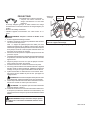
Indoor and Outdoor Motion Sensor Sensitivity
The detector is most sensitive to motion across its field of view.
Motion
Most SensitiveLeast Sensitive
Motion
Sensor Sensor
Aim Sensor Down
for Short Coverage
Aim Sensor Higher
for Long Coverage
Adjusting Indoor Motion Sensor Coverage
Maximum
Coverage Angle
Maximum Range
Outdoor Motion Sensor Coverage Area
70 ft.
(21 m)
8 ft.
(2.4 m)
180°
Aim Sensor Down
for Short Coverage
Aim Sensor Higher
for Long Coverage
Adjusting Outdoor Motion Sensor Coverage
3. Adjust RANGE Control. To increase sensitivity, turn the RANGE
control toward MAX. To decrease sensitivity, turn the RANGE
control toward MIN. Note: If the RANGE is set too high, false
triggering may result in some environments.
Note: When using test mode to check operation in the day time:
A. Set the DETECT control switch to DAY/NIGHT and
B. Set the ON-TIME control to TEST.
4. Set ON-TIME Control. Determine the amount of time you want
the connected device to stay on after motion is detected (1 or
5 minutes). Slide the ON-TIME control to the corresponding
setting.
IMPORTANT: Avoid Aiming Control At:
• Objects that change temperature rapidly, such as heating vents,
fans, and air conditioners. These air sources could cause false
triggering.
• Areas where pets or traffic may trigger the control.
• Nearby large, light colored objects reflecting light may trigger the
shut-off feature. Do not point other lights at the sensor.

9598-1116-09
ENGLISH
RECEIVER INFORMATION
All receivers have the following features and ratings:
• Rated for 120VAC/60Hz supply voltage.
• Light can be dimmed when used with remote control (OFF, 5
Selectable Dim Levels from Dimmest to Brightest, Full On).
• Remembers last selected dim setting.
• Not for use with Compact Fluorescent bulbs.
• When first turned on wait 15 seconds.
INDOOR PLUG-IN CONVERTER
Features and Ratings:
• Up to 300 Watt maximum incandescent load.
• No wiring required.
1. Plug in indoor receiver.
2. Plug in light you wish to control.
CAUTION: Do not exceed the maximum load limits listed
above.
3. Check operation. Activate transmitter being used with receiver
(see transmitter instructions). A signal will be sent to the receiver
to turn the receiver ON or OFF.
4. Using Remote By-Pass Switch. These receivers are equipped
with a remote by-pass switch. This switch allows the user to
select between AUTO and MANUAL modes. AUTO mode
allows the light to be operated by remote control or remote
motion sensor. MANUAL mode allows the plugged in light to
be operated manually.
5. Adjust audio alert volume (if applicable). Some models are
equipped with an audible alarm. The alarm sounds only when
the receiver is activated by the wireless motion sensor and
entry switch. The alarm volume is adjusted by the thumbwheel
on the side of the receiver unit.
Control Locations
Remote
By-Pass
Switch
Remote
By-Pass
Switch
Alarm Volume
ControlSpeaker
LAMP SOCKET CONVERTER
Features and Ratings:
• Up to 150 Watt maximum incandescent load.
• No wiring required.
1. Screw module into light socket.
2. Screw incandescent bulb up to rated wattage
into module.
CAUTION: Do not exceed the maximum load limits
listed above.
3. Check operation. Activate transmitter being used with receiver
(see transmitter instructions). A signal will be sent to the
receiver to turn the receiver ON or OFF.

10 598-1116-09
Junction box ground wire to green
ground screw on fixture.
Wiring Floodlight
WARNING: Risk of fire. Do not aim the lamps at a
combustible surface within 3 ft. (1 m).
White to
White
Black to
Black
Gasket
Mounting
Strap
Mounting
Bolt
Rubber
Plug
FLOODLIGHT
Features and Ratings:
• Up to 150 Watt maximum
incandescent load or 240 Watt
maximum halogen load (up to
75 Watt maximum incandescent,
or 120 Watt maximum halogen, per lampholder).
• Minimal wiring required.
• Install fixture in accordance with local codes.
WARNING: Turn power off at the fuse or circuit breaker.
1. Remove the existing light fixture.
2. Install the mounting strap as shown using two screws that fit
your junction box.
Note: The plastic hanger can be used to hold the fixture while
wiring. Thread the small end of the plastic hanger through the
hole in the center of the cover plate. Insert the small end into
one of the slots on the mounting strap.
3. Route the wires from the light receiver through the large gasket
holes.
4. Twist the junction box wires and fixture wires together as shown.
Secure with UL approved wire connectors.
5. Align the cover plate and cover plate gasket. Secure with
mounting bolt.
6. Push the rubber plug firmly into place.
7. Not intended for waterproof junction boxes. Fixture should be
surface mount only. Caulk the wall plate mounting surface with
silicone weather sealant.
8. Adjust the lamp holders by loosening the lock nuts. Note: Do
not rotate the lamp holders more than 180° from the factory
setting.
CAUTION: To avoid water damage and electrical shock,
keep lamp holders 30° below horizontal.
9. Screw incandescent bulb up to rated wattage into module.
When screwing in the lamps, do not overtighten.
CAUTION: Do not exceed the maximum load limits listed
above.
10. Check operation. Activate transmitter being used with receiver
(see transmitter instructions). A signal will be sent to the receiver
to turn the receiver ON or OFF.

11598-1116-09
ENGLISH
TROUBLESHOOTING GUIDE
POSSIBLE CAUSE
1. Circuit breaker or fuse is turned off.
2. Switch on device is turned off.
3. Interrupted by another device.
4. Does not respond immediately after
installation.
5. Signals from transmitter are being
blocked, or transmitter is out of range.
6. Weak battery in the transmitter.
7. Dip switches on transmitter and receiver
units do not match.
8. Device is defective.
1. Same as 5, 6, and 7 above.
1. Short term power line failure.
2. Another transmitter on the same
frequency.
SYMPTOM
Device does not come on.
Device does not turn off.
Device comes on randomly.
SOLUTION
1. Verify circuit breaker or fuse is turned
on.
2. Verify switched device is turned on.
3. Change codes on transmitter and
receiver units.
4. Wait for 90 second initialization period
(remote motion sensor).
5. Check for metal objects that could
block the signal, or reposition the
transmitter.
6. Check battery charge and replace if
necessary.
7. Verify code settings on transmitter and
receiver units are set the same.
8. Test using different device.
1. Same as 5, 6, and 7 above.
1. Next transmission from transmitter
will reset receiver to correct state.
2. Change codes on transmitter and
receiver units.
REGULATORY INFORMATION
This device complies with Part 15 of the FCC Rules and RSS-210 of Industry Canada. Operation is subject to the following two conditions:
(1) this device may not cause harmful interference, and (2) this device must accept any interference received, including interference
that may cause undesired operation.
The term “IC:” before the radio certification number only signifies that Industry Canada technical specifications were met.
The user is cautioned that changes or modifications not expressly approved by the party responsible for regulatory compliance could
void the user’s authority to operate the equipment.
TECHNICAL SERVICE
Please call 1-800-858-8501 for assistance before returning product to store.
If you experience a problem, follow this guide. You may also want to visit our Web site at: www.desatech.com. If the problem persists, call*
for assistance at 1-800-858-8501, 7:30 AM to 4:30 PM CST (M-F). You may also write* to:
DESA Specialty Products™
ATTN: Technical Service Specialty Products
P.O. Box 90004
Bowling Green, KY 42102-9004
* If contacting Technical Service, please have the following information available: Model Number, Date of Purchase, and Place of Purchase.
No Service Parts Available for this Product

12 598-1116-09
TWO YEAR LIMITED WARRANTY
This is a “Limited Warranty” which gives you specific legal rights. You may also have other rights which vary from state to state
or province to province.
For a period of two years from the date of purchase, any malfunction caused by factory defective parts or workmanship will be
corrected at no charge to you.
Not Covered - Repair service, adjustment and calibration due to misuse, abuse or negligence, light bulbs, batteries, and other
expendable items are not covered by this warranty. Unauthorized service or modification of the product or of any furnished
component will void this warranty in its entirety. This warranty does not include reimbursement for inconvenience, installation,
setup time, loss of use, unauthorized service, or return shipping charges.
This warranty covers only DESA Specialty Products™ assembled products and is not extended to other equipment and com-
ponents that a customer uses in conjunction with our products.
THIS WARRANTY IS EXPRESSLY IN LIEU OF ALL OTHER WARRANTIES, EXPRESS OR IMPLIED, INCLUDING ANY
WARRANTY, REPRESENTATION OR CONDITION OF MERCHANT ABILITY OR THAT THE PRODUCTS ARE FIT FOR
ANY PARTICULAR PURPOSE OR USE, AND SPECIFICALLY IN LIEU OF ALL SPECIAL, INDIRECT, INCIDENTAL, OR
CONSEQUENTIAL DAMAGES.
REPAIR OR REPLACEMENT SHALL BE THE SOLE REMEDY OF THE CUSTOMER AND THERE SHALL BE NO LIABILITY
ON THE PART OF DESA SPECIALTY PRODUCTS™ FOR ANY SPECIAL, INDIRECT, INCIDENTAL, OR CONSEQUENTIAL
DAMAGES, INCLUDING BUT NOT LIMITED TO ANY LOSS OF BUSINESS OR PROFITS, WHETHER OR NOT FORESEEABLE.
Some states or provinces do not allow the exclusion or limitation of incidental or consequential damages, so the above limitation or
exclusion may not apply to you. Proof of purchase is required for warranty claims.
DESA Specialty Products™ reserves the right to discontinue products and to change specifications at any time without incurring any
obligation to incorporate new features in products previously sold.

ESPAÑOL
13598-1116-09
ON
1 2 3
4
ON
1 2 3
4
ON
1 2 3
4
ON
1 2 3
4
ON
1 2 3
4
ON
1 2 3
4
© 2006 DESA Specialty Products™ 598-1116-09 S
CARACTERISTICAS
• Productos probados y aprobados por laboratorios UL/cUL y/o
FCC/IC.
• Distancia de operación: hasta 100 pies.
Los controles inalámbricos Heath
®
/Zenith para el alumbrado es-
tán diseñados para trabajar juntos. Simplemente determine cual
transmisor(es) le gustaría que controlen tal(es) receptor(es) y
fije la calibración del código para emparejar.
• Transmisores
– Control remoto
– Interruptor A añadible
– Interruptor de entrada
– Detector inalámbrico de mov
-
imiento para uso interior
– Detector inalámbrico de mov-
imiento para uso exterior
Productos a control remoto
Este manual incluye las instrucciones de operación para una variedad de productos a control remoto. Todos los productos funcionan
basándose en el mismo principio y usan la misma información para la calibración del código. Por favor lea todas las instrucciones y
tome en cuenta cualquier información específica relativa a su producto en particular.
ADVERTENCIAS:
. PARA USO SÓLO con bombillas incandescentes o halógenas de 120 voltios.
. NO LO USE con bombillas fluorescentes, electrodomésticos, fuentes de energía, alumbrado con bajo voltaje ni con ningún
otro aparato eléctrico.
• Receptores
– Convertidor enchufa-
ble para usarse bajo
techo
– Convertidor del zócalo
de la lámpara
– Reflector
Este manual sirve para los siguientes productos:
CALIBRACIONES DEL CÓDIGO
Nota: La mayoría de instalaciones de sólo un sistema no re-
querirán ningún cambio en la calibración del código. Para que
funcionen juntos los transmisor(es) y los receptor(es) deben
tener la misma calibración de código y de grupo. Los interrupto-
res del 1 al 3 fijan el código. El interruptor 4 fija el grupo (A o B).
Vea en la página 14 la ubicación de los interruptores.
DIM
ON
OFF
ON
OFF
DIM
Código del
receptor(es)
Código del transmisor(es)/
receptor(es)
Grupo “A”
Grupo “B”
Código del detector
remoto de movimiento
Grupo “A”
Ejemplo 1 - Calibraciones del código, sistema 1
(calibración de fábrica)
Controles del
lado izquierdo:
Controla un juego de
receptor(es) del gru-
po “A” o grupo “B”
Controles del lado
derecho: Controla un
juego de receptores
del grupo “A” o gru-
po “B”
Grupo “A”
Ejemplo 3 - Calibraciones del código con un
único transmisor
Cuando se use un transmisor de sólo un grupo (ejemplo: Transmisor
de puerta, interruptor “A” añadible, detector remoto de movimiento)
las calibraciones de código y grupo deben emparejar con los
receptor(es) para que el sistema funcione correctamente.
Nota: Esta calibración funcionará independientemente de los ejem
-
plos uno y dos porque la calibración del código es diferente.
Nota: El código puede también cambiarse para reducir los proble-
mas de interferencia que vienen de otros productos inalámbricos.
(ejemplo: Teléfonos inalámbricos, abridores de puertas de garajes,
etc.) Para más información vea Guía de Análisis de Averías.
( – Indica la posición del interruptor)
Ejemplo 2 - Calibraciones del código, sistema 2
Nota: Cuando opere más de un sistema independientemente el uno del
otro, fije cada sistema con un código diferente. Hay 8 códigos disponi-
bles al cambiar las calibraciones de los interruptores del 1 al 3.
Código del
receptor(es)
Grupo “A”
Código del
transmisor(es)
Interruptor del grupo
(Selección Grupo “A” mostrada)
Código del transmisor(es)/
receptor(es)

14 598-1116-09
Convertidor enchufable para usarse
bajo techo
UBICACIONES DE LOS INTERRUPTORES DE CIRCUITO IMPRESO
O
N
1
2 3
4
Interruptores
de circuito
impreso
1 2 3 4
ON
2032
3
V
L
i
t
h
i
u
m
B
a
t
t
e
r
y
DIM
Interruptor A añadible
Tapa de
acceso
1 2 3 4
ON
2032
3
V
L
i
t
h
i
u
m
B
a
t
t
e
r
y
DIM
Interruptor de entrada
Reflector
Convertidor del zócalo de la lámpara
1
2 3
4
Interruptores
de circuito
impreso
Tornillo
Tapa
Interruptores
de circuito
impreso
Detector inalámbrico de movimiento
para uso exterior
Interruptores
de circuito
impreso
DE TEC T
CO DES
1 2 3 4
DA
Y
NI GHT
NI GHT
ON L
Y
Interruptores de
circuito impreso
ON
1 2 3
4
Vista ampliada de un interruptor típico
del código (la calibración hecha en
fábrica es OFF- apagado)
Nota: La “X” ha sido colocada en los
interruptores para ayudar a aclarar las
calibraciones del código de la página
anterior.
CR2032
3 VOLTS
1 2 3 4
ON
Interruptores de
circuito impreso
Control remoto
Interruptores
de código
del lado
derecho
Tapa de la
batería
Interruptores
de código
del lado
izquierdo
ON DIP
1 2 3 4
ON DIP
1 2 3 4
Detector inalámbrico de movimiento
para uso interior
Interruptores
de circuito
impreso
CODE
1 2 3
4
ON
5 1 T EST
ON-TIME
(MINUTES)
MIN MAX
DETECT
RANGE
DAY
NIG HT
NIG HT
ONL
Y

ESPAÑOL
15598-1116-09
Importante: Espere de 1 a 2 segundos después de pulsar el botón
de un transmisor antes de pulsarlo de nuevo para permitir que la
transmisión se complete.
Nota: Si la luz no se prende o si se prende y apaga intermitente-
mente cuando se pulsan los botones del transmisor, vea la Guía
de Análisis de Averías.
Presilla opcional del visor del carro (incluida)
Para mayor conveniencia, en el control remoto se incluye una presilla
opcional del visor del carro que puede ser instalada.
1. Para unir (si se desea)la presilla del visor del carro al control
remoto empújela contra la ranura de la parte posterior del
control hasta que se cierre a presión en su lugar.
2. Para retirar esta presilla, inserte un destornillador plano
pequeño en la ranura de la parte posterior del control. Con
el destornillador, empuje suavemente la porción de la presilla
del visor que está dentro de la ranura mientras desde arriba
hala la presilla hacia fuera del control.
Nota: Para operar independientemente una segunda unidad recep
-
tora usando un único control remoto, asegúrese que el segundo
juego de interruptores de código (del lado derecho) emparejen
con los interruptores de código de cada receptor (Ver la sección
Calibraciones del Código).
• Lado izquierdo - Para calibrar los interruptores de código del
lado izquierdo.
• Lado derecho - Para calibrar los interruptores de código del
lado derecho.
Retiro de la presilla del visor – Vista posterior
Destornillador
plano
Presilla
opcional del
visor
Controles de las funciones
Lado izquierdo DIM
Lado izquierdo
(ON)ENCENDIDO
Lado izquierdo
(OFF)APAGADO
Lado derecho DIM
Lado derecho
(ON)ENCENDIDO
Lado derecho
(OFF)APAGADO
Nota: Un control remoto puede operar independientemente
dos unidades receptoras. Si se desea operar independien-
temente más de dos receptores, se necesitarán comprar
controles remotos adicionales.
1. Retire la aleta del compartimento de la batería. Retire la
tapa posterior del transmisor. Hale la aleta con suavidad
fuera del compartimento de la batería. Deslice la tapa
en el transmisor.
CONTROL REMOTO
2. Funciones del control remoto. Los tres botones del lado izquier-
do del control remoto hacen funcionar a una o más unidades
receptoras que tienen la misma calibración del código. Los tres
botones de la derecha harán funcionar un segundo juego de uno
o más receptores.
• ON: Enciende cualquier unidad receptora del mismo código que
este control remoto.
• OFF: Apaga cualquier unidad receptora del mismo código que
este control remoto.
• DIM: Activa la característica REDUCTORA de cualquier unidad
receptora del mismo código que este control remoto. Nota: Al pulsar
el botón DIM se pasa por los cinco niveles de luminosidad.
Vista posterior del control remoto
4 5 43
1 2 3
2
ON DIP
1 2 3 4
ON DIP
1 2 3 4
Compartimento
de la batería
(tipo A23)
Tapa de la batería
Aleta

16 598-1116-09
5. Continúe presionando el botón atenuador (DIM) hasta alcanzar
el nivel de atenuación deseado. Nota: El receptor memoriza la
última calibración de ATENUACIÓN usada. Para volver a la
última calibración, pulse y suelte el botón atenuador (DIM).
Nota: En caso de una falla de energía, la calibración del atenuador
se fija en el ajuste hecho en fábrica del 50%.
Importante: Luego de presionar un botón del transmisor espere
de 1 a 2 segundos para presionarlo de nuevo y permitir que se
complete la transmisión.
Nota: Si al presionar los botones del transmisor la luz no se
enciende ni lo hace en forma intermitente, vea Guía de Análisis
de Averías.
Reemplazo de la batería
El transmisor del interruptor de pared requiere para operar una
batería de litio de 3 voltios tipo CR2032. El transmisor se lo envía
con la batería instalada. Con uso normal la batería dura aproxi-
madamente 5 años. Retire la batería cuando no se vaya a utilizar
el transmisor por un período de tiempo extenso.
1. Coloque el pulgar en la tapa
de acceso y deslícela hacia
abajo para abrirla.
2. Doble hacia fuera y con
suavidad la aleta de traba.
La batería saltará.
3. Retire la batería del zócalo.
4. Instale en el zócalo la batería
de repuesto con el lado (+)
hacia arriba (vea la ilustración)
Presione la batería hasta que
la aleta de traba se cierre a
presión en su sitio.
5. Vuelva a colocar la puerta de
acceso deslizándola hacia
arriba hasta que se fije en
su sitio.
INTERRUPTOR A AÑADIBLE
Instalación
1. Retire la aleta del compartimiento de la batería.
Retire la tapa de la parte frontal del transmisor con
interruptor A añadible. Retire con suavidad la aleta
del compartimiento de la batería. Deslice la tapa en
el transmisor interruptor A añadible.
D
IM
Interruptor A añadible
Interruptor A
añadible
Botón ON/OFF
(encendido/
apagado)
Botón
atenuador
(DIM)
Tapa de acceso
D
IM
2. Seleccione un lugar para instalar el transmisor con interruptor
A añadible. Nota: El transmisor debería ubicarse hasta 100
pies (30m) del receptor. Nota: El transmisor debe montarse
aproximadamente a 4 pies del piso y en posición vertical.
3. Antes del montaje, sostenga el transmisor en la posición
seleccionada y verifique su operación (vea Operación). Nota:
Si el transmisor no opera correctamente, vea Guía del Análisis
de Averías.
4. Sostenga el transmisor en el sitio y marque los orificios de
montaje con un lápiz o con un objeto punzante.
5. Retire el transmisor y taladre orificios de 3/16 pulgadas.
Usando un martillo inserte en los orificios las anclas para
pared (provistas).
6. Fije el transmisor a la pared usando los dos tornillos (provis-
tos).
Operación
1. Verifique que el receptor haya sido instalado correctamente.
Vea Información del receptor en la página 22.
2. Pulse y suelte el botón ON (parte superior). La luz debería
encenderse con luminosidad total.
3. Pulse y suelte el botón OFF (parte inferior). La luz debería
apagarse.
4. Pulse y suelte el botón atenuador. La luz debería encenderse
al nivel ATENUADOR.
Retiro de la aleta de la batería
1 2 3 4
ON
2032
3
V
L
i
t
h
i
u
m
B
a
t
t
e
r
y
DIM
Compartimiento
de la batería (Tipo
CR2032)
Tapa de acceso
Aleta
1 2 3 4
ON
DIM
2032
3
V
L
i
t
h
i
u
m
B
a
t
t
e
r
y
Batería
de litio
CR2032
Aleta de
traba de la
batería
Tapa de
acceso
Retiro de la tapa de
acceso y la batería

ESPAÑOL
17598-1116-09
INTERRUPTOR DE ENTRADA
Instalación
Nota: El sistema de entrada incluye un transmisor y
un imán. El sistema puede usarse para dar señal sea
a una puerta o a una ventana que ha sido abierta o
para encender automáticamente la luz cuando se
ingresa en un armario, desván, habitación, etc.
1. Retire la aleta del compartimiento de la batería. Retire la tapa
posterior del transmisor usando un destornillador pequeño de
hoja plana. Hale con suavidad la aleta fuera del compartimiento
de la batería.
Retiro de la aleta de la batería
Consideraciones importantes:
• Los componentes del transmisor de entrada son sólo para usarlos
bajo techo.
• El transmisor debe ser instalado en el marco de la puerta o la
ventana (superficie fija). El imán debe ser instalado en la puerta
o la ventana (superficie móvil). Vea en la ilustración de abajo las
disposiciones de montaje y direcciones posibles del movimiento.
1 2 3 4
ON
CR2032
3 VOLTS
Batería (tipo
CR2032)
Transmisor
Aleta
Destornillador
plano
Possible Directions
of Movement
Possible Directions
of Movement
Possible Directions
of Movement
Possible Directions
of Movement
• Para completar el sistema se debe usar un receptor compatible.
El receptor debe estar ubicado dentro de 100 pies (30 m) del
transmisor (la distancia máxima puede variar dependiendo del
tipo de estructuras entre el transmisor y el receptor).
2. Seleccione la ubicación de montaje para el transmisor de
entrada. Nota: La separación máxima entre el transmisor y el
imán es de 3/8 de pulgada y las flechas ubicadas en la cara de
Transmisor instalado en superficie fija
Imán instalado en superficie móvil
Disposiciones de montaje y direcciones posibles del
movimiento
3/8" MAXIMUM
cada componente deben estar alineadas (Vea la ilustración).
También, las superficies frontales del transmisor y del imán
deben estar al ras. Si el imán está empotrado, use la extensión
del imán y los dos tornillos largos (provistos) para asegurar
una alineación correcta.
3. Antes del montaje, sostenga el transmisor y el imán en la
ubicación seleccionada y verifique el funcionamiento. Mien-
tras sostiene el transmisor fijo, mueva el imán alejándolo del
transmisor como simulando que la puerta o la ventana está
siendo abierta. Verifique que el LED rojo en el transmisor
destelle momentáneamente y que el receptor encienda la
luz. Vuelva a poner el imán en la posición original simulando
que la puerta o la ventana se está cerrando. Verifique que el
LED rojo en el transmisor destelle momentáneamente y que
el receptor apague la luz. Nota: Si el transmisor no funciona
correctamente, vea Guía de Análisis de Averías.
4. Montaje del transmisor
Montaje con tornillo: Una a la pared la tapa posterior del
transmisor usando los dos tornillos cortos (provistos). Coloque
a presión el transmisor en la tapa posterior.
Montaje con cinta: Coloque un pedazo largo de cinta espon-
josa (provista) a la tapa posterior del transmisor. Pegue en la
posición deseada del marco de la puerta o la ventana la tapa
posterior del transmisor. Coloque a presión el transmisor en
la tapa posterior.
5. Repita el paso 4 para unir el imán a la puerta o la ventana.
Reemplazo de la batería
El transmisor de entrada requiere para funcionar una batería de
litio de 3 voltios tipo CR2032. El transmisor viene con la batería
instalada. Con uso normal, la batería durará aproximadamente 5
años. Retire la batería cuando al transmisor no se lo vaya a usar
por un largo período de tiempo.
1. Retire el transmisor de
su tapa posterior usando
un destornillador peque-
ño de hoja plana.
2. Con cuidado haga pa-
lanca en la batería para
que se afloje usando un
destornillador pequeño
de hoja plana. La batería
saltará.
3. Instale la batería de
repuesto en el zócalo con
el lado positivo (+) hacia
arriba (vea la ilustración).
Presione sobre la batería
hasta que se coloque a
presión en su sitio.
4. Coloque a presión el
transmisor en la tapa posterior.
Nota: El imán no requiere de una batería.
CR2032
3 VOLTS
1 2 3 4
ON
Batería de litio CR2032
Destornillador
de hoja plana
Reemplazo de la batería
Transmisor
Direcciones posibles
de movimiento
Direcciones posibles
de movimiento
MÁXIMO 3/8 de pulgada

18 598-1116-09
DETECTOR INALÁMBRICO DE MOVIMIENTO
PARA USO INTERIOR Y EXTERIOR
Seleccione modo nocturno o modo de 24 horas
Estos detectores pueden detectar movimiento durante el día o la
noche o sólo por la noche. Para fijar el modo de detección, retire
la tapa del compartimiento de la batería deslizándola hacia abajo.
Si es necesario retire las baterías. Mueva el interruptor DETECT
(DETECTAR) ya sea a la posición DAY/NIGHT ó a la posición NIGHT
ONLY (SÓLO NOCHE). Vuelva a colocar el compartimiento de la
batería siguiendo a la inversa las instrucciones indicadas.
Instalación de las baterías
• Antes de montar el detector de movimiento para uso exterior,
retire la tapa del compartimiento de la batería deslizándola hacia
abajo.
• En detectores de movimiento para uso interior, instale las baterías
luego de colocar el detector.
Coloque las dos baterías AA según la polaridad marcada dentro del
compartimento de la batería. Vuelva a colocar el compartimiento de
la batería siguiendo a la inversa las instrucciones indicadas.
Características:
• No se requiere cableado.
• Margen de sensibilidad hasta 9.1 m. 150° de cobertura (Interior).
• Margen de sensibilidad hasta 21 m. 180° de cobertura (Exte-
rior).
• Sensibilidad ajustable.
• Operación diurna/nocturna o sólo nocturna.
• Modo prueba.
• Usa dos baterías AA.
• Puede instalarse directamente en la pared o usando un soporte
de montaje (incluido) (Interior).
• Montaje en pared o alero (Exterior).
• Controla los receptores hasta 30 m de distancia.
Detector inalámbrico de
movimiento para uso
exterior
O
N
D
ay
/
Night
N
ight
Only
5 1
Te
s
t
M
ax
Mi
n
Detector inalámbrico de
movimiento para uso
interior
DE TEC T
CO DES
1 2 3 4
DA
Y
NI GHT
NI GHT
ON L
Y
Control
detector
Compartimento de la batería
CODE
1 2 3
4
ON
5 1 TE ST
ON-TIME
(MINUTES)
MIN MAX
DETECT
RANGE
DAY
NIGH T
NIGH T
ONL
Y
Detector de movimiento
para uso exterior
(Vista posterior)
Detector de movimiento
para uso interior
(Vista frontal)
Consola de monta-
je tipo bola
Parte posterior del
detector
Ranuras para
la aleta
Sujeción de la consola de montaje tipo bola al
detector de movimiento para uso interior
(se muestra la instalación vertical)
Instalación del detector de movimiento para uso
interior usando el soporte opcional de montaje
Nota: Instale el detector de movimiento para uso interior de modo
que pueda girar hacia arriba o hacia abajo y así darle la cobertura
deseada por encima del nivel del suelo.
1. Fije la consola de montaje tipo bola a la parte posterior del
detector de movimiento. La consola de montaje tipo bola está
diseñada para instalarse en la parte posterior del detector en
tres direcciones posibles dependiendo de lo requerido por la
instalación. Para sujetar la consola de montaje tipo bola siga
los pasos que se indican:
• Determine la posición óptima de montaje del detector para
obtener la cobertura deseada.
• Determine el sitio óptimo de la consola de montaje para pared.
Montura
giratoria
de bola
Tornillo del soporte
de montaje tipo
bola
Aleta
Continuación

ESPAÑOL
19598-1116-09
O
N
D
ay
/
N
ight
Night
Only
5 1 Te
s
t
M
ax
M
in
Sujeción del detector de movimiento para uso interior a la
consola de montaje
Consola de
montaje
Tornillo de la
abrazadera
Tuerca
Detector
Tornillo de montaje
Montura giratoria de bola
Zócalo de la consola
de montaje
Tapa del compartimiento
de la batería
Instalación del detector de movimiento para uso
interior directamente en la pared
Nota: Instale el detector de movimiento para uso interior de modo que
quede aproximadamente a una altura sobre el suelo entre la cintura
y los hombros. (Ejemplo: Al mismo nivel o altura que un interruptor
de luz, debajo de la superficie superior del mostrador, etc.).
1. Determine la posición óptima de montaje del detector para
obtener la cobertura deseada. Retire las baterías.
2. Coloque el detector de movimiento para uso interior sobre la su-
perficie que lo va a instalar. Usando dos de los orificios posteriores
del compartimiento de la batería marque, con un lápiz o con un
punzón de marcar, las ubicaciones de los orificios.
3. Con una broca de 2,5 mm. (0,1 pulgadas), taladre dos orificios
guía para los tornillos de montaje. Si no lo instala directamente
a la madera o al espárrago de la madera, taladre orificios guía
de 5mm (0,2 pulgadas) y utilice las anclas de pared que se
incluyen.
4. Usando los dos tornillos provistos, fije el detector de movimiento
para uso interior a un objeto sólido y firme (ejemplo: pared,
armario, poste, etc.). Asegúrese que la unidad no tenga
obstrucciones en su línea de mira.
IMPORTANTE: Apriete a mano solamente - No apriete de-
masiado.
Fijación del detector de movimiento directamente a la pared
O
N
D
ay /
N
ight
N
ight
O
nly
5 1 T
est
M
a
x
M
in
O
N
D
ay /
N
igh
t
Night
O
nly
5 1 T
est
M
a
x
M
in
O
N
D
ay /
N
i
ght
N
ight
O
nly
5 1 T
es
t
M
ax
M
in
ON
D
ay /
N
ight
N
ig
ht
O
nl
y
5 1 T
es
t
M
ax
M
in
Tornillo de
montaje
Detector de
movimiento
Superficie
superior del
mostrador
• Inserte las aletas de la consola de montaje tipo bola en las
ranuras de la parte posterior del detector que mejor alineen
este detector con la consola de montaje de pared.
• Retire las baterías.
• Con un destornillador cabeza Phillips, inserte el tornillo de
montaje en el orificio del compartimiento de la batería que
alinee con el orificio posterior de la consola de montaje tipo
bola. Apriete bien.
2. Coloque el soporte de montaje del detector sobre la superficie
que lo va a instalar y con un lápiz o un punzón de marcar,
marque la ubicación del orificio.
3. Con una broca de 2,5 mm. (0,1 pulgadas), taladre dos orificios
guía para los tornillos de montaje. Si no lo instala directamente
a la madera o al espárrago de la madera, taladre orificios guía
de 5mm (0,2 pulgadas) y utilice las anclas de pared que se
incluyen.
4. Usando los dos tornillos provistos, fije el detector de movi-
miento para uso interior a un objeto sólido y firme (ejemplo:
pared, armario, poste, etc.). Asegúrese que la unidad no tenga
obstrucciones en su línea de mira. Nota: Sujete la consola de
montaje verticalmente si lo instala a una superficie curva como
un poste.
5. Instale el detector de movimiento a la consola de montaje.
Usando un destornillador cabeza Philips, afloje el tornillo de
la abrazadera en la consola de montaje. Inserte la montura
giratoria de bola del detector en el zócalo de la consola de
montaje (Nota: Usted debería oír un chasquido -un clic-). Apunte
el detector hacia el área que se requiere detectar. Apriete el
tornillo de la abrazadera.

20 598-1116-09
Instalación del detector de movimiento para uso
exterior
1. Instale la consola de montaje del detector en donde se nece-
site detectar movimiento. Acople esta consola de montaje a
un objeto robusto (ejemplo: árbol, poste, casa, etc.) usando
los dos tornillos provistos. Asegúrese que la unidad no tenga
obstrucciones en su línea de mira. Nota: Sujete la consola de
montaje verticalmente si lo instala a una superficie curva como
un poste.
2. Instale el detector de movimiento a la consola de montaje.
Usando un destornillador cabeza Philips, afloje el tornillo de
la abrazadera en la consola de montaje. Inserte la montura
giratoria de bola del detector en el zócalo de la consola de
montaje (Nota: Usted debería oír un chasquido -un clic-). Apunte
el detector hacia el área que se requiere detectar. Apriete el
tornillo de la abrazadera.
IMPORTANTE: El detector debe estar montado con la tapa
inferior hacia abajo con el fin de mantener la hermeticidad
contra el agua.
Instalación del detector de movimiento
Consola de montaje
Tornillo de la
abrazadera
Tuerca
Detector
Tornillo de montaje
Montura giratoria
de bola
Zócalo de la consola
de montaje
Revisión de la operación y de la regulación
Nota: Cuando lo prenda por primera vez o cuando cambie de
modalidad espere 1
1
/
2
minutos.
Localice en el detector de movimiento los controles de ALCANCE
y DURACIÓN:
• Detector de movimiento para uso interior - los controles de
ALCANCE y DURACIÓN están dentro del compartimiento de
la batería en la parte frontal del detector. Para fijar el control de
ALCANCE o el de DURACIÓN, retire la tapa del compartimiento
de la batería deslizándola hacia abajo.
• Detector de movimiento para uso exterior - Los controles
de ALCANCE y DURACIÓN están ubicados en la parte inferior
del detector. Usando las uñas de los dedos o un destornillador
pequeño de cabeza plana, haga suavemente palanca en la tapa
hasta que se abra.
1. Revise la operación. Ponga el control de DURACIÓN en el modo
TEST (PRUEBA). Camine frente a la unidad detectora. La luz
indicadora LED debe destellar cuando se detecta movimiento
(vea la ilustración de la página 21 para ubicar la luz LED).
2. Regule el detector. Gire el control de ALCANCE a la posición
media y el de DURACIÓN a la posición TEST. Camine por el
área de cobertura y note su posición cuando el LED empiece a
destellar. Afloje el tornillo de la abrazadera y mueva el detector
para cambiar el área de cobertura. Cuando termine apriete
el tornillo de la abrazadera. No apriete excesivamente este
tornillo.
3. Regule el control de alcance. Para incrementar la sensibilidad,
gire el control de ALCANCE hacia MAX. Para disminuir la
sensibilidad, gírelo hacia MIN. Nota: En algunos ambientes
si el ALCANCE se calibra demasiado alto, puede ocurrir una
falsa activación.
Nota: Cuando use el modo de prueba (Test) para comprobar
el funcionamiento durante el día:
A. Ponga el interruptor del control DETECT (DETECTAR) a
DAY/NIGHT (NOCHE/DÍA) y
B. Ponga el control ON-TIME (DURACIÓN) a TEST.
4. Fije el control de DURACIÓN. Determine la cantidad de tiempo
que desea que el dispositivo conectado permanezca encendido
luego que se detecta movimiento (1 ó 5 minutos). Mueva el
control de DURACIÓN a la configuración correspondiente.
IMPORTANTE:
Evite apuntar el control:
• Objetos que cambian rápidamente la temperatura, como sopladeros
de la calefacción, ventiladores y acondicionadores de aire. Estas
fuentes de calor podrían ocasionar una activación falsa.
• A áreas en donde las mascotas o el tráfico pueden activar el
control.
• En las cercanías de objetos grandes pintados con colores claros
cuyo reflejo puede activar el apagado. No enfoque otras luces
al detector.
Continuación
Page is loading ...
Page is loading ...
Page is loading ...
Page is loading ...
Page is loading ...
Page is loading ...
Page is loading ...
Page is loading ...
Page is loading ...
Page is loading ...
Page is loading ...
Page is loading ...
Page is loading ...
Page is loading ...
Page is loading ...
Page is loading ...
Page is loading ...
Page is loading ...
Page is loading ...
Page is loading ...
-
 1
1
-
 2
2
-
 3
3
-
 4
4
-
 5
5
-
 6
6
-
 7
7
-
 8
8
-
 9
9
-
 10
10
-
 11
11
-
 12
12
-
 13
13
-
 14
14
-
 15
15
-
 16
16
-
 17
17
-
 18
18
-
 19
19
-
 20
20
-
 21
21
-
 22
22
-
 23
23
-
 24
24
-
 25
25
-
 26
26
-
 27
27
-
 28
28
-
 29
29
-
 30
30
-
 31
31
-
 32
32
-
 33
33
-
 34
34
-
 35
35
-
 36
36
-
 37
37
-
 38
38
-
 39
39
-
 40
40


Heath Zenith 598-1116-10 Owner's manual
- Category
- Motion detectors
- Type
- Owner's manual
- This manual is also suitable for
Ask a question and I''ll find the answer in the document
Finding information in a document is now easier with AI
in other languages
Related papers
-
Heath Zenith 598-1116-10 User manual
-
 Heath SL-6005 User manual
-
-
-
-
-
-
ACE 598-1214-03 User manual
-
-

Other documents
-
Zenith WC-6053-WH - Heath - Motion Light Set User manual
-
Secure Home SH-5412 User manual
-
 Electripak 5412 User manual
-
Desa Compact 150 Watt Motion Sensing Halogen 5511 User manual
-
GE 12751 User manual
-
Chamberlain CWPIR Operating instructions
-
-
Defiant DF-6026-WH-B Installation guide
-
 Prime-Line N 6790 Operating instructions
-
 Prime-Line N 6870 Operating instructions


