Eaton Airflex 24WCB Installation, Operation and Maintenance Manual

Type
Installation, Operation and Maintenance Manual
Installation, Operation and Maintenance of
Airflex® WCB Water Cooled Tensioners
Ref.: Parts List #s
146246A thru 146298J
WC 11050
August, 1995 PDF Format
204054
Copyright Eaton Corp. 1995 All rights reserved.
Caution:
Use Only Genuine Airflex
Replacement Parts
The Airflex Division of Eaton Corporation recommends the use
of genuine Airflex replacement parts. The use of non-genuine
Airflex replacement parts could result in substandard product
performance, and may void your Eaton warranty. For optimum
performance, contact Airflex:
In the U.S.A. and Canada::
800-233-5926
Outside the U.S.A. and Canada:
(216) 281-2211
Warning
Forward this manual to the person responsible
for Installation, Operation and Maintenance of
the product described herein. Without access
to this information, faulty Installation, Operation
or Maintenance may result in personal injury or
equipment damage.
Table of Contents
1.0 INTRODUCTION . . . . . . . . . . . . . . . . . . . . . . . . . . . 9
1.1 Description . . . . . . . . . . . . . . . . . . . . . . . . . . . . 9
1.2 Specials . . . . . . . . . . . . . . . . . . . . . . . . . . . . . . 9
1.3 Upgrades . . . . . . . . . . . . . . . . . . . . . . . . . . . . . 10
1.4 How it Works . . . . . . . . . . . . . . . . . . . . . . . . . . . 10
2.0 INSTALLATION . . . . . . . . . . . . . . . . . . . . . . . . . . . . 10
2.1 Preperation . . . . . . . . . . . . . . . . . . . . . . . . . . . . 10
2.2 Alignment . . . . . . . . . . . . . . . . . . . . . . . . . . . . . 11
2.3 Mounting . . . . . . . . . . . . . . . . . . . . . . . . . . . . . 11
2.4 Air System . . . . . . . . . . . . . . . . . . . . . . . . . . . . 13
2.5 Coolant System . . . . . . . . . . . . . . . . . . . . . . . . . . 13
3.0 OPERATION . . . . . . . . . . . . . . . . . . . . . . . . . . . . . 15
3.1 Conditions of Operation . . . . . . . . . . . . . . . . . . . . . . 15
3.2 Pressure and Speed Limits . . . . . . . . . . . . . . . . . . . . . 15
4.0 PERIODIC MAINTENANCE . . . . . . . . . . . . . . . . . . . . . . . 16
4.1 Wear Adjustment (WCBs w/Stop Tubes) . . . . . . . . . . . . . . 16
4.2 Wear Adjustment (WCBs without Stop Tubes) . . . . . . . . . . . . 18
5.0 DISASSEMBLY, INSPECTION & ASSEMBLY . . . . . . . . . . . . . . . 21
5.1 Removal of WCB . . . . . . . . . . . . . . . . . . . . . . . . . . 21
5.2 Disassembly of WCB . . . . . . . . . . . . . . . . . . . . . . . . 21
5.3 Inspection of WCB componants . . . . . . . . . . . . . . . . . . . 22
5.4 Assembly of WCB (18, 24 & 36 WCBs with Stop Tubes) . . . . . . 22
5.5 Assembly of WCBs without Stop Tubes . . . . . . . . . . . . . . . 23
6.0 COMPONENT MAINTENANCE . . . . . . . . . . . . . . . . . . . . . 24
6.1 Cylinder Seal Replacement . . . . . . . . . . . . . . . . . . . . . 24
6.2 Friction Lining Replacement for WCBs (with screwed on linings) . . . 25
6.3 Friction Lining Replacement for 8 & 14 WCBs (Riveted Linings) . . . . 26
6.4 Wear Plate Replacement . . . . . . . . . . . . . . . . . . . . . . 27
7.0 WEAR LIMITS . . . . . . . . . . . . . . . . . . . . . . . . . . . . 29
8.0 PARTS LIST (Models with riveted linings & without stop tubes) . . . . . 30
9.0 PARTS LIST (Models with screwed on linings and stop tubes) . . . . . . 31
10.0 SUB-ASSEMBLIES . . . . . . . . . . . . . . . . . . . . . . . . . . 34
11.0 KITS . . . . . . . . . . . . . . . . . . . . . . . . . . . . . . . . . 37
PDF FORMAT
1
© Copyright Eaton Corp., 1994. All rights reserved.
Figure 1
8 WCB
14 WCB
Figure 2
NOTE: The coolant outlets should be positioned at the 12 o-clock position.
PDF FORMAT
2
© Copyright Eaton Corp., 1995. All rights reserved.
Figure 3
Item Description for 8 & 14 WCB (Figure 1 & 3))
Item Description Item Description Item Description
1 Mounting Flange Ass’y 10 Rivet 21 Inner Polypak
®
Seal
2 Mounting Flange 11 Washer 23 Outer Polypak
®
Seal
3 Wear Plate 12 Clamp Tube 28 Gear
4 Socket Head Screw 13 Pressure Plate Ass’y 29 Wear Spacer
5 Locknut 14 Pressure Plate 30 Reaction Plate Assy
6 Stud 15 Washer 31 Reaction Plate
7 Friction Disc Assy 17 Washer 33 Piston
8 Friction Disc 18 Locknut 34 Spring
9 Friction Disc Core 19 Cylinder 49 Socket Head Screw
For part number listing see section 8.0
PDF FORMAT
3
© Copyright Eaton Corp., 1995. All rights reserved.
18, 24 & 36 WCB Single Disc
Figure 4
PDF FORMAT
4
© Copyright Eaton Corp., 1995. All rights reserved.
18, 24 & 36 WCB Dual Disc
Figure 5
PDF FORMAT
5
© Copyright Eaton Corp., 1995. All rights reserved.
18, 24 & 36 WCB Triple Disc
Figure 6
PDF FORMAT
6
© Copyright Eaton Corp., 1995. All rights reserved.
Figure 7
18, 24 & 36 WCB Quad Disc
PDF FORMAT
7
© Copyright Eaton Corp., 1995. All rights reserved.
Item Description for 18, 24 & 36 WCB
Items for Figures , 4, 5, 6, 7 & 8 for 18, 24 & 36 WCB,s with screwed on linings and stop tubes
Item Desciption Item Description
1 Mounting Flange Sub-assembly 24 Warning Decal
2 Mounting Flange 25 Name Plate
3 Wear Plate 26 Drive Screw
4 Hex Head Screw 28 Gear
5 Locknut 29 Wear Spacer
6 Stud 30 Reaction Plate Sub-assembly
8 Friction Disc 31 Reaction Plate
9 Friction Disc Core 32 Decal Plate
12 Clamp Tube 33 Piston
13 Pressure Plate Sub-assembly 34 Release Spring
14 Pressure Plate 50 Inner Support Ring
17 Flat Washer 51 Outer Support Ring
18 Locknut 57 Flat Head Screw
19 Cylinder 58 Wear Ring
21 Polypak Seal 59 Stop Tube
23 Polypak Seal 80 Stop Tube
For part number listing see section 9.0
TABLE 1
Tensioner Mounting Register
Diameters - In. (mm)
Size Female Register Male Register
8WCB
8.375/8.378
(212.7/212.8)
12.125/12.122
(308.0/307.9)
14WCB
14.375/14.378
(365.1/365.2)
18.750/18.747
(476.3/476.2)
18WCB
18.250/18.253
(463.5/463.6)
23.250/23.247
(590.5/590.4)
24WCB
24.375/24.378
(619.1/619.2)
29.998/29.995
(761.9/761.8)
36WCB
18.375/18.378
(466.7/466.8)
44.498/44.493
(1130.2/1130.1)
Registers to be .125"-.188"(3.2-4.8mm) deep.
Fi
g
ure 8
NOTE:
The coolant outlets should be positioned at the 12 o-clock position.
PDF FORMAT
8
© Copyright Eaton Corp., 1995. All rights reserved.
1.0 INTRODUCTION
Throughout this manual, there are a number of
HAZARD WARNINGS
that must be read and
understood in order to prevent possible injury
and/or damage to the equipment. Three
signal words, "
DANGER
", "
WARNING
", and
"
CAUTION
" are used to indicate the severity
of a hazard and are preceded by the safety
alert symbol.
Denotes the most serious hazard, and is
used when serious injury or death WILL
result from misuse or failure to follow
specific instructions.
When serious injury or death MAY result
from misuse or failure to follow specific
instructions.
When injury or product/equipment
damage may result from misuse or
failure to follow specific instructions.
It is the responsibility and duty of all personnel
involved in the installation, operation and
maintenance of the equipment on which this
device is used to fully understand the
,
,
and
1.1 Description
1.1.1
The Airflex WCB water-cooled tensioner is
designed for constant tension applications. It is
exceptionally well suited for high inertia stop-
ping and rapid heat dissipation. The design of
the WCB tensioner permits midshaft or
endshaft mounting. The rugged construction
ensures long, trouble free service. Several
models are available having single and multiple
friction discs. The tensioner model number
identifies the number of discs and the disc
diameter. For example, 114WCB means one
14" diameter disc. When size, such as 14WCB,
is referred to in this manual, it means that the
information given applies to all models using
the 14" diameter disc; i.e., 114WCB, 214WCB,
etc.
1.1.2
Standard 8 and 14 WCB models have parts list
numbers ending with "B". These units have
riveted friction lining and no stop tubes or wear
rings.
1.1.3
Standard 18, 24 and 36 WCB models have
screwed on friction lining, stop tubes and wear
rings. These units have part list numbers
ending with "E".
1.1.4
Some earlier 18, 24 and 36 WCB units have
riveted friction lining and no stop tubes or
wear rings. These units have part list numbers
ending with "B".
1.1.5
Tensioners can be used for either closed loop or
open loop water systems.
1.1.6
This manual includes metric equivalents
usually shown in (#) following the U.S.
measurement system value. Be sure to use
the correct value.
1.2 Specials
1.2.1
WCB models with high coefficient lining are
designated with the following alphanumeric
designators:
1.2.2.1
Models ending with "C" (146XXXC) are
WCBs with riveted linings and no stop tubes.
8 and 14 WCB’s are current HI-CO elements
and 18,24 & 36 models are discontinued.
1.2.1.2
Models ending with "D" (146XXXD) are
WCBs with screwed on linings and stop tubes.
18, 24 & 36 models are current HI-CO
element s.
1.2.2
214WCB Models with an "A" (146XXXA)
designator are elements with a machined
cylinder face to accept a mounting flange to
accept a 108 WCB for dual purpose operation.
The only difference between the "A" model
and the "B model is the Cylinder (19) part
number. "A" models use P/N513398 for item
(19). All other parts on the part list is the same
as a "B" model element.
1.2.3
WCB Models with "G" (146XXXG)
designator have bonded standard lining.
To replace see table 12 in section 6.2 and order
a complete friction disc sub assembly.
PDF FORMAT
9
© Copyright Eaton Corp., 1995. All rights reserved.
1.2.4
114 WCB Models with "H" (146XXXH)
designator have a special friction disc core for
mating with a 112.5 WC gear. The friction
disc core (9) P/N is 416126 and the friction
disc sub-assembly (7) P/N is 416125, all other
parts are the same as the "B" model WCB.
1.2.5
WCB models with "J" (146XXXJ) designator
have Corrosion Resistant Pistons and Standard
screwed on friction linings. Contact
Airflex for piston (33) P/N’s.
1.2.6
WCB models with "K" (146XXXK) designator
have Corrosion Resistant Pistons and High
Coefficient screwed on friction linings(8). Call
Airflex for piston (33) P/N’s.
1.2.7
WCB models with part list numbers, not just
alphanumeric designator, other than listed on
cover use WC 11040.
1.3 Upgrades
1.3.1
18, 24 and 36 WCB elements ending with a
"B" (146XXXB) alphanumeric designators
have been discontinued, however, existing
models may be upgraded to new standards.
To upgrade the element you must change the
friction disc subassembly with cores having
screwed on linings. See table X, all discs must
be changed. Also stop tubes (59) & (80), wear
rings (58) must be installed. See the part list in
section 9.0 for part numbers and quantities for
the individual elements.
Note: If these changes have been made stamp
out the "B" letter designator and stamp the
"E" designator.
1.4 How It Works
1.4.1
Refer to Figure 1. Air is introduced to the unit
causing the pressure plate assembly (13) to
move and make contact with the friction discs
(8). Torque is transmitted through the studs (6)
to the mounting flange (2). The release springs
(34) assist in disengagement and retraction of
the piston and pressure plate. High heat
dissipation is accomplished by passing water
through a special cavity behind copper wear
plates (3).
2.0 INSTALLATION
Only qualified maintenance personnel
should install, adjust or repair these
units. Faulty workmanship will result in
unreasonable exposure to hazardous
conditions or personal injury.
Read these instructions thoroughly and
review until you fully understand the
installation sequence before proceeding
with the work described in this section.
Failure to follow these instructions will
result in unreasonable exposure to
hazardous conditions or personal injury.
Do not paint the clamp tubes (12) or
the springs (34), as this may hinder the
engagement or disengagement of the
tensioner.
Maximum ambient temperature is 110
o
F
(43
o
C ). Minimum ambient temperature
for closed loop systems using ethylene
glycol antifreeze is 0
o
F (-18
o
C). For open
loop systems using water, the minimum
temperature is 45
o
F (7
o
C).
Note: Some three and four disc units may
require support on the cylinder end of the
tensioner in certain high torque applications.
Contact the factory for specific application
information.
2.1 Preparation
2.1.1
Table 2 shows the relationship between the
tensioner mounting surface and the end of the
gear (dimension "A" on Figure 1, 3-6 ). The
gear is bored and keyed for a resulting Class
FN2S interference fit for inch shafting and ISO
System S7h6 for metric shafting.
PDF FORMAT
10
© Copyright Eaton Corp., 1995. All rights reserved.
TABLE 4
Fastener Description and Assembly Torque - ft-lb (Nm) (Lubed)
Fastener 8WCB 14WCB 18WCB 24WCB 36WCB
Item #18
Description 1/2-13NC-3 3/4-10NC-3 3/4-10NC-3
1 1/8-7NC
Gr. 8
1 3/8-6NC
Gr. 8
Torque 60 (81) 150 (203) 150 (203) 500 (677) 750 (1016)
Item # 5
Description #10-24NC 1/4NC2 5/16-18NC 5/16-18NC 3/8-16NC2
Torque 5 (7) 12 (16) 25(31) 25(31) 40(54)
Mounting
Screw
Description
1/2-13NC-2
Gr.8
5/8-11NC-2
Gr. 8
5/8-11NC-2
Gr. 8
5/8-11NC-2
Gr. 8
1-8NC2 Gr. 8
Quantity 4 6 10 10 14
Torque 70 (95) 150 (203) 150 (203) 150 (203) 660 (895)
2.1.2
Figures 2 and 8 and Table 1 show the mount-
ing dimensions for the tensioner to the
machine frame or reaction bracket. Note that
a male or female register may be used.
2.2 Alignment
2.2.1
For proper operation and service life, the
tensioner reaction member must be aligned to
the shaft within the limits shown on Table 3.
Proper alignment is necessary to ensure
that the friction discs track properly.
Improper alignment will result in
excessive wear to the friction material
and its mating surfaces, the gear and
splined bore of the friction disc
assembly. See Figure 9.
2.3 Mounting
2.3.1
The WCB must be mounted to a clean, rigid
surface with hardened flat washers and
screws of the grade, quantity, and size and tor-
qued to the values identified in Table 4 for
each WCB size. Mounting to a rigid surface
minimizes any deflection during operation and
ensures that the friction discs will track
properly on the copper wear plates.
Correct Track
Incorrect Track
Fig. 9
TABLE 2
"A" Dimension on Figure 1 - in. (mm)
Size Single Dual Triple Quad
8WCB
1.00
(25.4)
1.38
(35.0)
N/A N/A
14WCB
1.06
(26.9)
1.69
(42.9)
N/A N/A
18WCB
1.25
(31.8)
1.25
(31.8)
0.75
(19.1)
N/A
24WCB
1.38
(35.1)
1.00
(25.4)
0.63
(16.0)
1.38
(35.1)
36WCB
1.50
(38.1)
N/A
2.38
(60.5)
2.38
(60.5)
TABLE 3
Alignment Requirements
Size
Concentricity of
Shaft and Brake
In. (mm)
Perpendicularity of
Mounting Flange(2)
to Shaft - In. (mm)
8WCB
0.005 (0.13) 0.005 (0.13)
14WCB
0.010 (0.25) 0.007 (0.18)
18WCB
0.010 (0.25) 0.010 (0.25)
24WCB
0.010 (0.25) 0.012 (0.30)
36WCB
0.010 (0.25) 0.019 (0.48)
Perpendicularity referenced to outside diameter of
mounting flange from shaft center line (TIR).
PDF FORMAT
11
© Copyright Eaton Corp., 1995. All rights reserved.
Use only the proper number and grade
fasteners shown in Table 4. Use of
commercial grade (Grade 2) fasteners
where Grade 8 fasteners are specified
may result in failure of the fasteners and
a sudden and drastic reduction in brake
torque.
Make sure that the water inlets and
outlets are at the 6 o’clock and 12
o’clock positions, respectively. See Fig-
ures 2 & 8. This will ensure that there
will be no air pockets in the water cavity
during operation, which would allow the
tensioner to overheat.
Table 5
Air inlet size
Model Thread Size
8 WCB
3/8-18 NPT
14 WCB
1/2-14 NPT
18 WCB
1/2-14 NPT
24 WCB
1/2-14 NPT
36 WCB
3/4-14 NPT
2.3.2
To facilitate the tensioner mounting process,
the friction disc assemblies should be aligned
to the gear and centered in the tensioner. With
the tensioner laying on the floor, lower the gear
(28) slowly and very carefully into the splined
bore of the friction disc assemblies (7). Adjust
the discs so that they are centered in the
tensioner and fit the gear. Apply and maintain
an air pressure of 25 PSIG (1.7 bar) to the
cylinder. This will engage and hold the discs in
position to facilitate tensioner installation.
Remove the gear.
2.3.3
Ensure that the shaft is free of nicks or burrs
and the key fits properly in the shaft and gear.
2.3.4
Apply a light coat of anti-seizing compound to
the shaft and key. Tap the key into the shaft
keyway.
2.3.5
Press the gear onto the shaft, making sure
that the dimension between the gear and
the tensioner mounting surface ("A") is
maintained. See Figure 1 and Table 1. Heating
the gear uniformly to 250
o
F (121
o
C) will
expand the bore and ease assembly.
TABLE 6
Coolant Supply Data
Size
Thermal
Rating
1
HP (kW)
Water Inlet
and Outlet
Pipe Size
Min. Flow
Rate
2
GPM
(dm3/min)
100% Water
Min. Flow
Rate
2
GPM
(dm3/min)
70% Water,
30% Ethylene
Glycol by Vol.
Min. Flow
Rate
2
GPM
(dm3/min)
60% Water,
40% Ethylene
Glycol by Vol.
Min. Flow
Rate
2
GPM
(dm3/min)
50% Water,
50% Ethylene
Glycol by Vol.
108
30 (22.4) 1/2-14NPT 3 (11.4) 3.5 (13.4) 3.9 (14.7) 4.5 (17.0)
208
60 (44.7) 1/2-14NPT 6 22.7) 7 (26.8) 7.8 (29.4) 9 (33.9)
114
60 (44.7) 1/2-14NPT 6 (22.7) 7 (26.8) 7.8 (29.4) 9 (33.9)
214
120 (89.4) 1/2-14NPT 12 (45.4) 14 (53.6) 15.6 (58.8) 18 (67.9)
118
120 (89.4) 1/2-14NPT 12 (45.4) 14 (53.6) 15.6 (58.8) 18 (67.9)
218
240 (179) 1/2-14NPT 24 (91) 28 (106) 31 (117) 36 (136)
318
360 (268) 1/2-14NPT 36 (136) 42 (161) 47 (176) 54 (204)
124
270 (201) 3/4-14 NPT 27 (102) 32 (121) 35 (132) 40 (151)
224
540 (402) 3/4-14 NPT 54 (204) 64 (242) 70 (265) 80 (303)
324
810 (603) 3/4-14 NPT 81 (306) 96 (363) 105 (396) 120 (453)
424
1080 (804) 3/4-14 NPT 108 (408) 128 (484) 140 (528) 160 (604)
136
650 (485) 1 1/4-11 NPT 65 (246) 76 (288) 84 (318) 98 (371)
236
1300 (970) 1 1/4-11 NPT 130 (492) 152 (576) 168 (636) 196 (742)
336
1950 (1454) 1 1/4-11 NPT 195 (738) 228 (863) 253 (985) 294 (1113)
436
2600 (1940) 1 1/4-11 NPT 260 (984) 304 (1152) 336 (1272) 392 (1484)
1
Thermal rating based on a 70
o
F (21
o
C) water inlet temperature rise between inlet and outlet.
2
Flow rate is based on requirement of 1 U.S. GPM per 10 HP thermal dissipation.
PDF FORMAT
12
© Copyright Eaton Corp., 1995. All rights reserved.
For an Airflex supplied plated gear, do
not heat the gear to more than 300
o
F
(150
o
C). Temperatures in excess of
300
o
F (150
o
C) will cause the plating to
separate from the gear.
2.3.6
Apply a thin coat of Molub-alloy O.G.
®
to the
gear teeth.
2.3.7
Using lifting equipment and straps, lift the
tensioner and slide it over the gear. Fasten it to
the mounting surface using the hardware
called for in Table 4.
2.3.8
Torque the screws to the values called for in Ta-
ble 4 using a crosswise tightening sequence.
Release the air pressure applied in 2.3.2
2.4 Air System
Maximum allowable air pressure is 150
PSIG (10.3 bar). Application of pressure
exceeding maximum allowable may
result in damage to the tensioner.
2.4.1
All pipes should be free of metal chips, cutting
compound and any other foreign matter. Pipe
ends should be reamed after cutting to
eliminate possible restrictions. A minimum of
bends and elbows should be used.
2.4.2
Air inlets for the WCB are on the face of the
cylinder (19). See table 5. Use only clean,
filtered air (a 50 micron filter or better is recom-
mended) which is free of excess moisture.
2.5 Coolant System
Maximum allowable water pressure is
45 PSIG (3.1 bar). Application of
pressure exceeding maximum allowable
may result in damage to the tensioner.
2.5.1
Coolant supply connections to the tensioner
should provide a parallel flow through each
section of the tensioner. Series flow is not
generally recommended, contact Airflex for
specific applications. Inlet and outlet coolant
manifolds must be provided with flexible
connecting hose to each tensioner coolant
section. Coolant supply connection to the
tensioner must be flexible to allow axial travel
of the pressure plate and reaction plate during
tensioner operation. Coolant and coolant
supply lines should be free of foreign material
(a 500 micron water filter is recommended).
Reductions in the recommended line diameter
should be avoided. Avoid loops and bends in
the lines which may create air pockets, which
substantially reduce the flow of coolant. Figure
10 illustrates a typical closed loop liquid to
liquid coolant system. The heat exchanger and
temperature control would be replaced with a
radiator, fan and motor in a liquid to air system.
Figure 10
PDF FORMAT
13
© Copyright Eaton Corp., 1995. All rights reserved.
2.5.2
Figure 10 shows the flow control valve settings
for each type of element depending on the
number of friction surfaces to be cooled.
Improper or low coolant temperature can
cause condensation to occur on the
friction surfaces which will affect torque
and wear performances. Coolant should
be shut off when element is not in use.
Make sure that the water inlets and
outlets are at the 6 o’clock and 12
o’clock positions, respectively. This will
ensure that there will be no air pockets in
the water cavity during operation, which
would allow the tensioner to overheat.
2.5.3
The coolant supply and discharge pipe sizes,
along with minimum flow rates for the
tensioner rated horsepower, are given in
Table 6.
2.5.4
Each coolant cavity of each WCB tensioner has
been statically tested at the factory before
shipment. If leakage is suspected, a static or
dynamic test may be made as follows:
Static Pressure Test:
First, bleed all air from within the coolant
cavity. Air bleeding must be accomplished by
running coolant through the cavity with the
tensioner secured in its operating position. Af-
ter the air has been removed, install a pipe plug
in the outlet and apply 45 PSIG (3.1 bar) cool-
ant pressure measured at the inlet to the water
cavity. Maintain this pressure for 30
minutes. Check for leakage at O.D. and I.D.
seal areas.
Do not apply air pressure to the
cylinder of the tensioner during static
coolant pressure testing. Surge pressures
exceeding 45 PSIG (3.1 bar) could be
developed within the coolant cavities
which will cause damage to the seals.
Dynamic Flow Test:
Dynamic flow testing of the tensioner should
be conducted at the required flow rate for the
rated HP dissipation and coolant quality, as
given in Table 6. Inlet pressure is not to exceed
45 PSIG (3.1 bar).
There should be no restrictions on the outlet
side of the brake to cause any back pressure to
the unit. Coolant inlet and hose size should be
as given in Table 6. Check for leakage at the
O.D. and I.D. seal areas.
2.5.5
The coolant supply temperature at the inlet
should be 100
o
F (38
o
C) or lower. The coolant
outlet temperature should not exceed the
values given in Table 6. However, in no event
should there be more than a 50
o
F (28
o
C)
temperature rise between inlet and outlet. See
Table 7 for maximum allowable outlet coolant
temperature with a water/ethylene glycol mix.
2.5.6
Open Loop Systems
For efficient operation of the WCB, an
adequate supply of filtered fresh water is
required. (See 2.5.1-2.5.2). Excessive water
hardness promotes the formation of scale
deposits, which, in time, will affect the service
life of the WCB unit. Water of high acidity may
cause electrolytic corrosion between the
dissimilar metals used in the WCB. Water
treatment should be considered if the proper-
ties of the water exceed the following:
Equivalent calcium carbonate content
hardness): Maximum 100 p.p.m.
pH value: 7.0 to 9.0.
2.5.7
Closed Loop Systems
For efficient operation of the WCB in a closed
loop system, ethylene glycol coolant conform-
ing to SAE Standard J1034 should be used.
For preparation of the proper concentration of a
water/ethylene glycol mixture, use makeup
water which is low in corrosive ions such as
chlorides and sulfates.
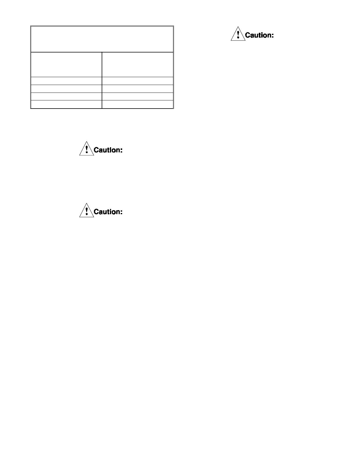
TABLE 7
Maximum Mixture Outlet
Coolant Temperature
Water/Ethylene
Glycol Mixture
% by Volume
Maximum Outlet
Coolant Temperature
o
F (
o
C)
100/0 150 (66)
70/30 165 (74)
60/40 165 (74)
50/50 170 (77)
PDF FORMAT
14
© Copyright Eaton Corp., 1995. All rights reserved.
TABLE 8
Maximum Disc Speeds
Size
Max. Slip Speed
RPM
Max. Disc Speed
RPM
8WCB
2150 3580
14WCB
1260 2045
18WCB
955 1600
24WCB
715 1200
36WCB
475 700
pH value of the water/ethylene glycol mixture:
7.5. to 10.5.
3.0 OPERATION
3.1 Conditions of Operation
The following Hazard Warnings are to be fol-
lowed for proper WCB functioning:
The maximum recommended operating
air pressure is 150 PSIG (10.3 bar). Air
pressure in excess of 150 PSIG (10.3
bar) will cause high stress in various
parts of the tensioner. Do not risk per-
sonal injury or damage to the equipment!
Protective means must be used to
prevent rain, water, oil, grease, dirt or
coolant from coming into contact with
the surfaces of the friction discs (8) or
the wear plates (3). Oil or grease on
these parts will significantly reduce the
torque capacity of the unit. Dirt or cool-
ant will produce erratic torque. Do not
risk personal injury or damage to the
equipment!
The friction disc assembly (7) maximum
disc speed must not exceed the speeds
listed in Table 8. Exposure to speeds in
excess of these values may cause the
friction discs to burst and result in
extensive damage to the tensioner
and/or cause personal injury.
For proper cooling of the WCB tensioner,
it is required that the coolant inlet be
located at the 6 o’clock position and the
outlet be located at the 12 o’clock
position. This will assure that all coolant
cavities are filled and will prevent
overheating. Refer to Figure 2 & 8.
For operation in subfreezing tempera-
tures, ethylene glycol antifreeze must be
added to the water. The antifreeze
content of the mixture is critical and
should not exceed 50% by volume since
excessive amounts will reduce cooling
capacity and can cause coolant leakage
due to overheating. Refer to Section 2.5
and Table 6.
3.2 Pressure and Speed Limits
3.2.1
Maximum applied air pressure is 150 PSIG
(10.3 bar). Maximum water pressure measured
at the inlet of the tensioner is 45 PSIG (3.1 bar).
3.2.2
Maximum slip speeds and (free wheeling) disc
speeds are shown in Table 8.
Excessive slip speeds will result in rapid
friction material wear. For good life, the
values in Table 8 should not be exceeded.
A minimum wear in period of four hours
at 50% of the rated horsepower is
recommended for the friction couple to
achieve rated torque.
PDF FORMAT
15
© Copyright Eaton Corp., 1995. All rights reserved.
4.0 PERIODIC MAINTENANCE
Before doing any maintenance work on
the WCB unit, make sure that the
machinery will remain in a safe position.
Failure to do so could result is serious
injury or possibly death.
Only qualified maintenance personnel
should install, adjust or repair these WCB
units. Faulty workmanship will result in
unreasonable exposure to hazardous
conditions or personal injury.
Read these instructions thoroughly and
review until you fully understand the
parts replacement steps before proceed-
ing with the work described in this
section. Failure to follow these instruc-
tions can result in unreasonable
exposure to hazardous conditions or
personal injury.
4.1 Wear Adjustments (WCB,s w/Stop
Tubes)
4.1.1
Single disc WCB,s
Note: Item numbers (#) are shown on
Figure 3.
4.1.1.1
There is no adjustment for single disc
elements. When the pressure plate (13)
bottoms against the stop tubes (59) , replace
friction material and inspect wear plates for
wear. See section 6.0.
Note: Stop tubes may be added to 18, 24 &
36 WCB single elements that did not originally
come equipped with stop tubes. Order Item
(58), (59) and (80) from parts list for WCB
elements including stop tubes.(Part lists
alpha-numeric number ends with "E".)
See section 9.0.
4.1.2
Dual, Triple & Quad disc WCBs
Note: Items (#) referenced in Figures
4, 5 and 6.
4.1.2.1
Dual disc elements have one adjustment, triple
disc elements have two adjustments and quad
disc elements have three adjustments. Follow
the wear spacer adjustment procedures in
section 4.1.3 for each adjustment made.
Note: Stop tubes may be added to 18, 24 &
36 WCB multi disc elements that did not
originally come equipped with stop tubes. Or-
der Items (58), (59) & (80) from parts list for
WCB elements including stop tubes. Part lists’
alpha-numeric number ends with "E". See sec-
tion 9.0.
4.1.3
Wear adjustment procedures (Multi disc)
Note: Item numbers (#) are shown on
Figures 4, 5 and 6.
Note:
On all units, the friction material must be
replaced when worn to the bottom of the
groove on the friction lining. See Figure 11.
See Table 17 in Section 7.0 for new wear
groove depth.
4.1.3.1
Disconnect air and water supply lines from the
tensioner.
4.1.3.2
While supporting the cylinder (19), loosen the
locknuts (18) ONE TURN AT TIME and in an
alternating (crosswise) pattern until the spring
force is completely relieved. Remove the
locknuts and washers (17). Mark all of the
water outlet ports for identification. Deep well
sockets are required. See table 9 for size and
depth of socket required.
4.1.3.3
Using lifting equipment, carefully remove the
cylinder (19) and piston (33) as an assembly.
Set aside in a clean area. (Piston side up.)
Note:
If a stud (6) should happen to come
loose, remove it completely, clean the threads
on the stud and the threads in the mounting
flange. Apply Locquic
®
Primer Grade "T" to the
stud threads. After the threads have dried,
assemble to the mounting flange using Loctite
®
#262. The end of the stud must not extend
past the mounting surface of the mounting
flange.
PDF FORMAT
16
© Copyright Eaton Corp., 1995. All rights reserved.
Loctite
®
#262 must be shaken prior to
application.
Loctit e
®
#262 may irritate sensitive skin.
Refer to the product label for proper
safety precautions.
4.1.3.4
Using lifting equipment, remove the pressure
plate assembly (13) and carefully place it on a
suitable work surface with the wear plate (3)
facing up. Do not damage the wear plate.
4.1.3.5
Remove the friction disc assembly, the reaction
plate assembly (30), release springs (34), stop
tubes (59) or (80)** and wear ring (58) from
each stud and set aside Repeat for three and
four disc units.
4.1.3.6
Remove the clamp tubes (12) and one wear
spacer (29) from each stud. Reinstall the clamp
tubes, set aside the removed wear spacers and
ONLY one wear ring (58) from each stop tube
that was removed.
4.1.3.7
Slide the friction disc assembly
onto the gear.
4.1.3.8
Place a release spring over every other clamp
tube. Install required number of wear rings (58)
and install one stop tube** on every fourth
stud without release springs and slide the
reaction plate assembly onto the clamp tubes.
NOTE: Quantity of wear rings re-installed at
each location should be same as quantity of
wear spacers installed.
The stop tubes (80)** on 324 WCB and
424 WCB units must be installed in the
center or center two positions shown on
figure 5 & 6. These stop tubes are identi-
fied by a small hole drilled into the side.
Improper installation will cause the
element to bind.
** NOTE: On 324 WCB and 424 WCB units
use Item (80) for the center set of stop tubes.
See Figure 5 and 6. These stop tubes are
identified by a small hole drilled into the side.
Wear
Grooves
Fig. 11
Wear
Spacer
Fig. 12
Table 9
Socket size and depth
Model Nut Size Socket Depth
108
3/4"
1 3/8"
208
1 1/2"
114
1 1/16"
1 1/2"
214
2 1/8"
118
1 1/16"
1 3/4"
218
2 3/8"
318
2 1/4"
124
1 /5/8"
1 3/4"
224
2 1/4"
324
6 5/8"
424
7 1/8"
136
2"
3 1/4"
236
4"
336
5 1/2"
436
6 1/5"
PDF FORMAT
17
© Copyright Eaton Corp., 1995. All rights reserved.
4.1.3.9
For multi-disc units, repeat steps 4.1.3.7 and
4.1.3.8 for each additional friction disc and
reaction plate * * .
4.1.3.10
Slide the pressure plate and the cylinder/piston
assembly onto the studs. Lubricate the threads
on the end of the studs with 30 wt. oil or anti-
seizing compound and install the washers
(17),wear spacers (29) and the locknuts (18)
removed in 4.1.3.6.
4.1.3.11
The wear spacers are "stored" under the
locknuts and washers for use after replacing
the friction discs. See Figure 12.
4.1.3.12
Discard un-used wear rings. New wear rings
are included in friction disc replacement kits.
4.1.4
While supporting the weight of the
cylinder/piston assembly, tighten the locknuts,
ONE TURN AT A TIME and in an alternating
(crosswise) pattern until the cylinder is seated
firmly against the clamp tubes. Torque the
locknuts to the appropriate value. See Table 4.
The locknuts (18) must be tightened
gradually to prevent damage to the
tensioner components.
4.1.5
Check that clearance exists between friction
discs and wear plates.
4.1.6
Reinstall air and coolant lines per 2.0.
4.2 Wear Adjustments (WCBs
without stop tubes)
4.2.1
Measuring Lining Wear
Periodically examine the tensioner for
wear of linings and wear plates. Failure
to perform this examination will result in
excessive wear, a significant reduction in
torque, and may result in personal injury
and/or damage to the machinery.
4.2.1
Wear limits for the WCB components
are shown in Section 7.0. If any wear
limit has been reached or exceeded, that
component must be repaired or replaced.
Note: Item numbers (#) are shown on
Figure 1.
4.2.2
Single Disc Units
Apply approximately 25 PSIG (1.7 bar) air
pressure to the cylinder to engage the
tensioner. Measure the gap "X" between the
cylinder (19) and the pressure plate (13) or the
gap "Y" between the pressure plate (13) and
the mounting flange (2) as shown in Figure
13. If the gap exceeds the limits shown in Ta-
ble 9, the friction discs and/or wear plates
must be inspected to ensure that the wear
limits listed in section 9.0, Table 10 have not
been exceeded.
4.2.3
Multi-disc Units
Apply approximately 25 PSIG (1.7 bar) air
pressure to the cylinder to engage the
tensioner. Measure the gap "X" between the
cylinder (19) and the pressure plate (13) or the
gap "Y" or "Z" between the pressure plate
(13) and the reaction plates (31) and the gap
"Y" between the reaction plate (31) and the
mounting flange (2) as shown in Figure 14, 15
and 16. If the gap exceeds the limits shown in
Table 10, the friction discs and/or wear plates
must be inspected to ensure that the wear
limits listed in section 7.0.
If wear adjustment is not made, the
piston may pop out of the cylinder result-
ing in loss of torque and/or seal damage.
4.2.4
Wear Adjustment
Premature wear adjustment may result
in improper disc clearances.
If a wear adjustment is not made, the
piston may be allowed to travel past the
end of the cylinder resulting in a sudden
loss of air pressure and a complete loss
in torque.
4.2.5
Disconnect air and water supply lines
from the tensioner.
PDF FORMAT
18
© Copyright Eaton Corp., 1995. All rights reserved.
Figure 14
Figure 15
Figure 13
Figure 16
PDF FORMAT
19
© Copyright Eaton Corp., 1995. All rights reserved.
  • Page 1 1
  • Page 2 2
  • Page 3 3
  • Page 4 4
  • Page 5 5
  • Page 6 6
  • Page 7 7
  • Page 8 8
  • Page 9 9
  • Page 10 10
  • Page 11 11
  • Page 12 12
  • Page 13 13
  • Page 14 14
  • Page 15 15
  • Page 16 16
  • Page 17 17
  • Page 18 18
  • Page 19 19
  • Page 20 20
  • Page 21 21
  • Page 22 22
  • Page 23 23
  • Page 24 24
  • Page 25 25
  • Page 26 26
  • Page 27 27
  • Page 28 28
  • Page 29 29
  • Page 30 30
  • Page 31 31
  • Page 32 32
  • Page 33 33
  • Page 34 34
  • Page 35 35
  • Page 36 36
  • Page 37 37
  • Page 38 38
  • Page 39 39
  • Page 40 40
  • Page 41 41
  • Page 42 42

Eaton Airflex 24WCB Installation, Operation and Maintenance Manual

Type
Installation, Operation and Maintenance Manual

Ask a question and I''ll find the answer in the document

Finding information in a document is now easier with AI