DeWalt 7in & 9in Large Angle Grinder DWTD28499X Owner's manual
- Category
- Power tools
- Type
- Owner's manual

If you have questions or comments, contact us.
Pour toute question ou tout commentaire, nous contacter.
Si tiene dudas o comentarios, contáctenos.
1-800-4-DeWALT
Instruction Manual
Guide D’utilisation
Manual de instrucciones
D28499, DWE4557, DWE4557G, DWE4559CN, DWE4559NG,
DWE4559CNG, DWE4559N, DWE4597, DWE4597N, DWE4599N
Heavy Duty Large Angle Grinders
Grandes rectifieuses coudées de service intensif
Esmeriladoras de ángulo grande para trabajo pesado
final page size: 8.5 x 5.5 in

ENGLISH
English (original instructions) 1
Français (traduction de la notice d’instructions originale) 16
Español (traducido de las instrucciones originales) 34

ENGLISH
1
English (original instructions)
Definitions: Safety Alert Symbols and Words
This instruction manual uses the following safety alert symbols and words to alert you to hazardous situations and your risk
of personal injury or property damage.
DANGER: Indicates an imminently hazardous situation which, if not avoided, will result in death or seriousinjury.
WARNING: Indicates a potentially hazardous situation which, if not avoided, could result in death or seriousinjury.
CAUTION: Indicates a potentially hazardous situation which, if not avoided, may result in minor or moderateinjury.
(Used without word) Indicates a safety related message.
NOTICE: Indicates a practice not related to personal injury which, if not avoided, may result in propertydamage.
WARNING! Read all safety warnings and all
instructions. Failure to follow the warnings and
instructions may result in electric shock, fire and/or
seriousinjury.
WARNING: To reduce the risk of injury, read the
instructionmanual.
If you have any questions or comments about this or
any
DeWALT
tool, call us toll free at:
1-800-4-
DeWALT
(1-800-433-9258).
1
Trigger switch
2
Lock-off button
3
Lock-on button
4
Spindle lock button
5
Spindle (Fig.J)
6
Guard
7
Soft mount (Fig.R)
8
Side handle
9
LED indicator
10
Anti-vibration ring
11
Dust ejection port
Fig. A
11
4
6
9
1
2
8
10
3

ENGLISH
2
GENERAL POWER TOOL SAFETY WARNINGS
WARNING! Read all safety warnings and all
instructions. Failure to follow the warnings and
instructions may result in electric shock, fire and/or
seriousinjury.
SAVE ALL WARNINGS AND
INSTRUCTIONS FOR FUTURE
REFERENCE
The term “power tool” in the warnings refers to your mains-
operated (corded) power tool or battery-operated (cordless)
powertool.
1) Work Area Safety
a ) Keep work area clean and well lit. Cluttered or dark
areas inviteaccidents.
b ) Do not operate power tools in explosive atmospheres,
such as in the presence of flammable liquids, gases or
dust. Power tools create sparks which may ignite the
dust orfumes.
c ) Keep children and bystanders away while operating a
power tool. Distractions can cause you to losecontrol.
2) Electrical Safety
a ) Power tool plugs must match the outlet. Never
modify the plug in any way. Do not use any
adapter plugs with earthed (grounded) power
tools. Unmodified plugs and matching outlets will
reduce risk of electricshock.
b ) Avoid body contact with earthed or grounded
surfaces such as pipes, radiators, ranges and
refrigerators. There is an increased risk of electric
shock if your body is earthed orgrounded.
c ) Do not expose power tools to rain or wet
conditions. Water entering a power tool will increase
the risk of electricshock.
d ) Do not abuse the cord. Never use the cord for
carrying, pulling or unplugging the power tool.
Keep cord away from heat, oil, sharp edges or
moving parts. Damaged or entangled cords increase
the risk of electricshock.
e ) When operating a power tool outdoors, use an
extension cord suitable for outdoor use. Use of
a cord suitable for outdoor use reduces the risk of
electricshock.
f ) If operating a power tool in a damp location
is unavoidable, use a ground fault circuit
interrupter (GFCI) protected supply. Use of a GFCI
reduces the risk of electricshock.
3) Personal Safety
a ) Stay alert, watch what you are doing and use
common sense when operating a power tool. Do
not use a power tool while you are tired or under
the influence of drugs, alcohol or medication. A
moment of inattention while operating power tools
may result in serious personalinjury.
b ) Use personal protective equipment. Always wear
eye protection. Protective equipment such as dust
mask, non-skid safety shoes, hard hat, or hearing
protection used for appropriate conditions will reduce
personalinjuries.
c ) Prevent unintentional starting. Ensure the
switch is in the off position before connecting to
power source and/or battery pack, picking up or
carrying the tool. Carrying power tools with your
finger on the switch or energizing power tools that
have the switch on invitesaccidents.
d ) Remove any adjusting key or wrench before
turning the power tool on. A wrench or a key left
attached to a rotating part of the power tool may
result in personalinjury.
e ) Do not overreach. Keep proper footing and
balance at all times. This enables better control of
the power tool in unexpectedsituations.
f ) Dress properly. Do not wear loose clothing or
jewelry. Keep your hair, clothing and gloves
away from moving parts. Loose clothes, jewelry or
long hair can be caught in movingparts.
g ) If devices are provided for the connection of dust
extraction and collection facilities, ensure these
are connected and properly used. Use of dust
collection can reduce dust-relatedhazards.
4) Power Tool Use and Care
a ) Do not force the power tool. Use the correct
power tool for your application. The correct power
tool will do the job better and safer at the rate for
which it wasdesigned.
b ) Do not use the power tool if the switch does not
turn it on and off. Any power tool that cannot be
controlled with the switch is dangerous and must
berepaired.
c ) Disconnect the plug from the power source and/
or the battery pack from the power tool before
making any adjustments, changing accessories,
or storing power tools. Such preventive safety
measures reduce the risk of starting the power
toolaccidentally.
d ) Store idle power tools out of the reach of children
and do not allow persons unfamiliar with the
power tool or these instructions to operate the
power tool. Power tools are dangerous in the hands
of untrainedusers.
e ) Maintain power tools. Check for misalignment or
binding of moving parts, breakage of parts and
any other condition that may affect the power
tool’s operation. If damaged, have the power
tool repaired before use. Many accidents are
caused by poorly maintained powertools.
f ) Keep cutting tools sharp and clean. Properly
maintained cutting tools with sharp cutting edges are
less likely to bind and are easier tocontrol.
g ) Use the power tool, accessories and tool bits, etc.
in accordance with these instructions, taking
into account the working conditions and the
work to be performed. Use of the power tool for

ENGLISH
3
operations different from those intended could result
in a hazardoussituation.
5) Service
a ) Have your power tool serviced by a qualified
repair person using only identical replacement
parts. This will ensure that the safety of the power
tool ismaintained.
SAFETY INSTRUCTIONS FOR ALL
OPERATIONS
Safety Warnings Common for Grinding,
Sanding, Wire Brushing, Polishing or
Abrasive, Cutting-Off Operations
a ) This power tool is intended to function as a
grinder, sander, wire brush, polisher or cut-off
tool. Read all safety warnings, instructions,
illustrations and specifications provided with
this power tool. Failure to follow all instructions
listed below may result in electric shock, fire and/or
serious injury.
b ) Do not use accessories which are not specifically
designed and recommended by the tool
manufacturer. Just because the accessory can
be attached to your power tool, it does not assure
safeoperation.
c ) The rated speed of the accessory must be at least
equal to the maximum speed marked on the
power tool. Accessories running faster than their
rated speed can break and fly apart.
d ) The outside diameter and the thickness of your
accessory must be within the capacity rating of
your power tool. Incorrectly sized accessories cannot
be adequately guarded or controlled.
e ) Threaded mounting of accessories must match
the grinder spindle thread. For accessories
mounted by flanges, the arbor hole of the
accessory must fit the locating diameter of the
flange. Accessories that do not match the mounting
hardware of the power tool will run out of balance,
vibrate excessively and may cause loss of control.
f ) Do not use a damaged accessory. Before each
use inspect the accessory such as abrasive
wheels for chips and cracks, backing pad for
cracks, tear or excess wear, wire brush for loose
or cracked wires. If power tool or accessory
is dropped, inspect for damage or install an
undamaged accessory. After inspecting and
installing an accessory, position yourself and
bystanders away from the plane of the rotating
accessory and run the power tool at maximum
no-load speed for one minute. Damaged
accessories will normally break apart during this
testtime.
g ) Wear personal protective equipment. Depending
on application, use face shield, safety goggles
or safety glasses. As appropriate, wear dust
mask, hearing protectors, gloves and workshop
apron capable of stopping small abrasive or
workpiece fragments. The eye protection must
be capable of stopping flying debris generated by
various operations. The dust mask or respirator must
be capable of filtrating particles generated by your
operation. Prolonged exposure to high intensity noise
may cause hearing loss.
h ) Keep bystanders a safe distance away from work
area. Anyone entering the work area must wear
personal protective equipment. Fragments of
workpiece or of a broken accessory may fly away and
cause injury beyond immediate area of operation.
i ) Hold power tool by insulated gripping surfaces
only, when performing an operation where the
cutting accessory may contact hidden wiring or
its own cord. Cutting accessory contacting a “live”
wire may make exposed metal parts of the power tool
“live” and could give the operator an electric shock.
j ) Position the cord clear of the spinning accessory.
If you lose control, the cord may be cut or snagged
and your hand or arm may be pulled into the
spinningaccessory.
k ) Never lay the power tool down until the
accessory has come to a complete stop. The
spinning accessory may grab the surface and pull the
power tool out of your control.
l ) Do not run the power tool while carrying it at
your side. Accidental contact with the spinning
accessory could snag your clothing, pulling the
accessory into your body.
m ) Regularly clean the power tool’s air vents. The
motor’s fan will draw the dust inside the housing and
excessive accumulation of powdered metal may cause
electrical hazards.
n ) Do not operate the power tool near flammable
materials. Sparks could ignite these materials.
o ) Do not use accessories that require liquid
coolants. Using water or other liquid coolants may
result in electrocution or shock.
p ) When starting the tool with a new or
replacement wheel, a new or replacement
wire brush installed, or if you are unsure of the
condition of the wheel, hold the tool in a well
protected area and let it run for one minute. If
the wheel has an undetected crack or flaw, it should
burst in less than one minute. If the wire brush has
loose wires, they will be detected. Never start the tool
with a person in line with the wheel. This includes the
operator.
Kickback and Related Warnings
Kickback is a sudden reaction to a pinched or snagged
rotating wheel, backing pad, brush or any other accessory.
Pinching or snagging causes rapid stalling of the rotating
accessory which in turn causes the uncontrolled power tool to
be forced in the direction opposite of the accessory’s rotation
at the point of the binding.

ENGLISH
4
For example, if an abrasive wheel is snagged or pinched by
the workpiece, the edge of the wheel that is entering into the
pinch point can dig into the surface of the material causing
the wheel to climb out or kick out. The wheel may either jump
toward or away from the operator, depending on direction
of the wheel’s movement at the point of pinching. Abrasive
wheels may also break under these conditions.
Kickback is the result of power tool misuse and/or incorrect
operating procedures or conditions and can be avoided by
taking proper precautions as given below:
a ) Maintain a firm grip on the power tool and
position your body and arm to allow you to resist
kickback forces. Always use auxiliary handle, if
provided, for maximum control over kickback or
torque reaction during start up. The operator can
control torque reaction or kickback forces, if proper
precautions are taken.
b ) Never place your hand near the rotating
accessory. Accessory may kickback over your hand.
c ) Do not position your body in the area where
power tool will move if kickback occurs. Kickback
will propel the tool in direction opposite to the wheel’s
movement at the point of snagging.
d ) Use special care when working corners, sharp
edges etc. Avoid bouncing and snagging the
accessory. Corners, sharp edges or bouncing have
a tendency to snag the rotating accessory and cause
loss of control or kickback.
e ) Do not attach a saw chain woodcarving blade
or toothed saw blade. Such blades create frequent
kickback and loss of control.
Safety Warnings Specific for Grinding and
Abrasive Cutting-Off Operations
a ) Use only wheel types that are recommended for
your power tool and the specific guard designed
for the selected wheel. Wheels for which the power
tool was not designed cannot be adequately guarded
and are unsafe.
b ) The grinding surface of center depressed
wheels must be mounted below the plane of
the guard lip. An improperly mounted wheel that
projects through the plane of the guard lip cannot be
adequately protected.
c ) The guard must be securely attached to the
power tool and positioned for maximum safety,
so the least amount of wheel is exposed towards
the operator. The guard helps to protect operator
from broken wheel fragments, accidental contact with
wheel , and sparks that could ignite clothing.
d ) Wheels must be used only for recommended
applications. For example: do not grind with the
side of cut-off wheel. Abrasive cut-off wheels are
intended for peripheral grinding, side forces applied to
these wheels may cause them to shatter.
e ) Always use undamaged wheel flanges that are
of correct size and shape for your selected wheel.
Proper wheel flanges support the wheel thus reducing
the possibility of wheel breakage. Flanges for cut-off
wheels may be different from grinding wheel flanges.
f ) Do not use worn down wheels from larger power
tools. Wheel intended for larger power tool is not
suitable for the higher speed of a smaller tool and
may burst.
Additional Safety Warnings Specific for
Abrasive Cutting-Off Operations
a ) Do not “jam” the cut-off wheel or apply excessive
pressure. Do not attempt to make an excessive
depth of cut. Overstressing the wheel increases the
loading and susceptibility to twisting or binding of
the wheel in the cut and the possibility of kickback or
wheel breakage.
b ) Do not position your body in line with and
behind the rotating wheel. When the wheel, at the
point of operation, is moving away from your body,
the possible kickback may propel the spinning wheel
and the power tool directly at you.
c ) When wheel is binding or when interrupting
a cut for any reason, switch off the power tool
and hold the power tool motionless until the
wheel comes to a complete stop. Never attempt
to remove the cut-off wheel from the cut while
the wheel is in motion otherwise kickback may
occur. Investigate and take corrective action to
eliminate the cause of wheel binding.
d ) Do not restart the cutting operation in the
workpiece. Let the wheel reach full speed and
carefully reenter the cut. The wheel may bind,
walk up or kickback if the power tool is restarted in
theworkpiece.
e ) Support panels or any oversized workpiece
to minimize the risk of wheel pinching and
kickback. Large workpieces tend to sag under their
own weight. Supports must be placed under the
workpiece near the line of cut and near the edge of the
workpiece on both sides of the wheel.
f ) Use extra caution when making a “pocket
cut” into existing walls or other blind areas.
The protruding wheel may cut gas or water pipes,
electrical wiring or objects that can cause kickback.
Safety Warnings Specific for Sanding
Operations
a ) Do not use excessively oversized sanding disc
paper. Follow manufacturer's recommendations
when selecting sanding paper. Larger sanding
paper extending beyond the sanding pad presents a
laceration hazard and may cause snagging, tearing of
the disc or kickback.

ENGLISH
5
Safety Warnings Specific for Polishing
Operations
a ) Do not allow any loose portion of the polishing
bonnet or its attachment strings to spin freely.
Tuck away or trim any loose attachment strings.
Loose and spinning attachment strings can entangle
your fingers or snag on the workpiece.
Safety Warnings Specific for Wire
Brushing Operations
a ) Be aware that wire bristles are thrown by the
brush even during ordinary operation. Do not
overstress the wires by applying excessive load
to the brush. The wire bristles can easily penetrate
light clothing and/or skin.
b ) If the use of a guard is recommended for wire
brushing, do not allow any interference of the
wire wheel or brush with the guard. Wire wheel or
brush may expand in diameter due to work load and
centrifugal forces.
c ) Safety Glasses: Safety Goggles or safety glasses with
side shields and a full face shield compliant with ANSI
Z87.1 must be worn by the operator and others that
are within 50 feet of the use of thisproduct.
Additional Safety Rules for Grinders
WARNING: The grinding wheel or accessory may
loosen during coast-down of the tool when shut
off. If grinding wheel or accessory loosens, it may
dismount from the machine and may cause serious
personal injury.
• Use of accessories not specified in this manual is not
recommended and may be hazardous. Use of power
boosters that would cause the tool to be driven at speeds
greater than its rated speed constitutes misuse.
• Use clamps or another practical way to secure and
support the workpiece to a stable platform. Holding
the work by hand or against your body leaves it unstable
and may lead to loss of control.
• Avoid bouncing the wheel or giving it rough
treatment. If this occurs, stop the tool and inspect the
wheel for cracks or flaws.
• Always handle and store wheels in a careful manner.
• Never cut into area that may contain electrical
wiring or piping. Serious injury may result.
• Do not operate this tool for long periods of time.
Vibration caused by the operating action of this tool may
cause permanent injury to fingers, hands, and arms. Use
gloves to provide extra cushion, take frequent rest periods,
and limit daily time of use.
• Direct the Dust Ejection System (DES) away from
operator and coworkers. Serious injury may result.
• When the gear case grip is properly installed, the use of the
side handle is not required.
• When not in use, place grinder on a stable surface
where it will not move inadvertantly, roll or cause a
tripping or falling hazard. Serious personal injury may
result.
Additional Safety Information
WARNING: ALWAYS use safety glasses. Everyday
eyeglasses are NOT safety glasses. Also use face or
dust mask if cutting operation is dusty. ALWAYS WEAR
CERTIFIED SAFETYEQUIPMENT:
• ANSI Z87.1 eye protection (CAN/CSA Z94.3),
• ANSI S12.6 (S3.19) hearing protection,
• NIOSH/OSHA/MSHA respiratoryprotection.
WARNING: Some dust created by power sanding,
sawing, grinding, drilling, and other construction
activities contains chemicals known to the State
of California to cause cancer, birth defects or
other reproductive harm. Some examples of these
chemicalsare:
• lead from lead-based paints,
• crystalline silica from bricks and cement and other
masonry products, and
• arsenic and chromium from chemically-
treatedlumber.
Your risk from these exposures varies, depending on how
often you do this type of work. To reduce your exposure to
these chemicals: work in a well ventilated area, and work with
approved safety equipment, such as those dust masks that are
specially designed to filter out microscopicparticles.
• Avoid prolonged contact with dust from power
sanding, sawing, grinding, drilling, and other
construction activities. Wear protective clothing and
wash exposed areas with soap and water. Allowing
dust to get into your mouth, eyes, or lay on the skin may
promote absorption of harmfulchemicals.
WARNING: Use of this tool can generate and/
or disperse dust, which may cause serious and
permanent respiratory or other injury. Always use
NIOSH/OSHA approved respiratory protection
appropriate for the dust exposure. Direct particles
away from face andbody.
WARNING: Always wear proper personal hearing
protection that conforms to ANSI S12.6 (S3.19)
during use. Under some conditions and duration
of use, noise from this product may contribute to
hearingloss.
CAUTION: When not in use, place tool on its side
on a stable surface where it will not cause a
tripping or falling hazard. Some tools with large
battery packs will stand upright on the battery pack
but may be easily knockedover.
• Air vents often cover moving parts and should be
avoided. Loose clothes, jewelry or long hair can be
caught in movingparts.
• An extension cord must have adequate wire size
(AWG or American Wire Gauge) for safety. The smaller
the gauge number of the wire, the greater the capacity

ENGLISH
6
of the cable, that is, 16 gauge has more capacity than 18
gauge. An undersized cord will cause a drop in line voltage
resulting in loss of power and overheating. When using
more than one extension to make up the total length,
be sure each individual extension contains at least the
minimum wire size. The following table shows the correct
size to use depending on cord length and nameplate
ampere rating. If in doubt, use the next heavier gauge. The
lower the gauge number, the heavier thecord.
Minimum Gauge for Cord Sets
Volts
Total Length of Cord in Feet
(meters)
120 V 25 (7.6) 50 (15.2) 100 (30.5) 150 (45.7)
240 V 50 (15.2) 100 (30.5) 200 (61.0) 300 (91.4)
Ampere Rating
American Wire Gauge
More
Than
Not
More
Than
0 6 18 16 16 14
6 10 18 16 14 12
10 12 16 16 14 12
12 16 14 12 Not Recommended
The label on your tool may include the following symbols. The
symbols and their definitions are asfollows:
V ......................... volts
Hz .......................hertz
min ..................... minutes
or DC ......direct current
...................... Class I Construction
(grounded)
…/min ..............per minute
BPM .................... beats per minute
IPM ..................... impacts per minute
RPM .................... revolutions per
minute
sfpm ................... surface feet per
minute
SPM .................... strokes per minute
A ......................... amperes
W ........................watts
or AC ...........alternating current
or AC/DC .... alternating or
direct current
...................... Class II
Construction
(double insulated)
n
o
.......................no load speed
n .........................rated speed
......................earthing terminal
.....................safety alert symbol
.....................visible radiation
..................... wear respiratory
protection
..................... wear eye
protection
..................... wear hearing
protection
..................... read all
documentation
SAVE THESE INSTRUCTIONS FOR
FUTURE USE
Motor
Be sure your power supply agrees with the nameplate
marking. Voltage decrease of more than 10% will cause loss
of power and overheating.
DeWALT
tools are factory tested;
if this tool does not operate, check power supply.
Familiarization
Large angle grinders are designed for heavy material
removal in extended use applications. The following
grinders are described in this manual:
SKU Description RPM
D28499 9" Angle Grinder 6,000
SKU Description RPM
DWE4557G 7" Angle Grinder 8,500
DWE4559NG 9" Angle Grinder 6,500
DWE4559CNG 9" Angle Grinder 6,500
DWE4597 7" Angle Grinder 8,500
DWE4597N 7" Angle Grinder 8,500
DWE4599N 9" Angle Grinder 6,500
COMPONENTS (FIG. A)
WARNING: Never modify the power tool or any part
of it. Damage or personal injury couldresult.
Refer to Figure A at the beginning of this manual for a
complete list ofcomponents.
INTENDED USE
Your grinder is designed for professional grinding, sanding,
wire brushing, polishing or abrasive, cutting-off applications.
DO NOT use under wet conditions or in presence of
flammable liquids orgases.
Your grinder is a professional power tool. DO NOT let
children come into contact with the tool. Supervision is
required when inexperienced operators use thistool.
Anti-Vibration Rear Handle (Fig. A)
The anti-vibration ring
10
reduces handle vibration and
user fatigue in extended use applications.
Dust Ejection System
The dust ejection system deflects debris that would be
harmful to the motor and allows cleaner air to pass over
themotor.
Keyless Guard
This allows for tool-free guard change and adjustment.
E-switch Protection™
DWE4597, DWE4597N, DWE4599N
The ON/OFF trigger switch has a no-volt release function.
In the event of a power outage or other unexpected shut
down, the trigger switch will need to be cycled (turned on
and off) to restart tool.
E-Clutch™
DWE4597, DWE4597N, DWE4599N
This unit is equipped with an E-Clutch™ (Electronic Clutch),
which in the event of a high-load or wheel pinch, the
unit will be shut off to reduce the reaction torque to the
user. The switch needs to be cycled (turned on and off) to
restarttool.
Power-OFF™ OVERLOAD Protection
DWE4597, DWE4597N, DWE4599N
The power supply to the motor will be reduced in case
of motor overload. With continued motor overload, the
tool will shut off. The switch needs to be cycled (turned
on and off) to restart tool. The tool will power off each
time the current load reaches the overload current value
(motor burn-up point). If continued overload shutdowns
occur, apply less force/weight on the tool until the tool will
function without the overload engaging.

ENGLISH
7
Complete electronic control™
DWE4597, DWE4597N, DWE4599N
The internal electronic speed control offers consistent wheel
speed while using the tool.
Electronic Soft Start
DWE4597, DWE4597N, DWE4599N
This feature limits the initial start up momentum, allowing
the speed to build up gradually over a 1 second period.
ASSEMBLY AND ADJUSTMENTS
WARNING: To reduce the risk of serious personal
injury, turn unit off and disconnect it from
power source before making any adjustments or
removing/installing attachments or accessories.
An accidental start-up can causeinjury.
Attaching Side Handle (Fig. B)
The side handle
8
can be fitted to either side or the top of
the gear case in the threaded holes. The side positions are
designed for optimized balance in surface finishing and
grinding applications. The side handle must be used at all
times to maintain proper control of the tool. Before using
the tool, check that the handle is tightened se cure ly.
Fig. B
NOTE: The D28499 offers 5 handle locations for
additionalversatility.
AntI-Vibration Side Handle
DWE4597, DWE4597N, DWE4599N
The anti-vibration side handle reduces vibration and user
fatigue in extended use applications.
Gear Case Grip (Fig. C)
DWE4559CN, DWE4559CNG
The DWE4559CN and DWE4559CNG include a soft grip
cover for the gear case that can be used as a gripping
surface only for pipeline grinding and wire brushing where
the edge of the wheel is used for grinding and cleaning and
precise control is needed to ensure accuracy. As with any
gripping surface, maintain firm grip during use. The side
handle should be used as the secondary grip surface for all
other applications.
Fig. C
The gear case grip may be purchased at additional cost.
Please call 1–800–4-
DeWALT
(1–800–433–9258) or visit our
website: www.
DeWALT
.com.
Rotating the Gear Case (Fig. D)
For applications in which a tool will be dedicated for uses
in edge grinding and finishing work, the gear case may be
rotated 90° left or right of its original position.
Fig. D
1. Remove the four corner screws attaching the gear case
to motor housing.
2. Without separating the gear case from motor housing,
rotate the gear case head to desired position.
NOTE: If the gear case and motor housing become
separated by more than 1/8" (3.17 mm), the tool must be
serviced and re-assembled by a
DeWALT
service center.
Failure to have the tool serviced may cause brush, motor
and bearing failure.
3. Reinstall screws to attach the gear case to the
motor housing. Tighten screws to 20 in.-lbs. torque.
Overtightening could cause screws to strip.
Rotating the Rear Handle (Fig. E)
D28499 Only
1. Unlock the rear handle by pulling out the handle re lease
lever
12
.
Fig. E
12

ENGLISH
8
2. Rotate handle into available 0°, 30°, 60°, or 90° position
left OR right of center.
3. Push in the handle release lever.
4. Before turning the tool on, ensure that the handle is
locked into a position and the handle release lever
has returned to the original position flush with the
toolhousing.
Wheel Mounting Accessories and
Attachments
It is important to choose the correct guards, backing pads
and flanges to use with grinder accessories. Refer to the
Accessories Chart for more information on choosing the
correct wheel mounting accessories.
Attachments
Attachments designed specifically for this grinder can be
purchased through
DeWALT
dealers and
DeWALT
Factory
Service centers.
9" Type 27 guard D284939
9" Type 28 guard D284938
7" Type 27 guard D284937
5"–6" Type 11 flaring cup guard
with flange
D284936
4" Type 11 flaring cup guard
with flange
D284934
Type 11 flaring cup wheel
backing flange
N197992
Type 1 flange set D284932
7" Type 1 guard D284931
Grinding backing flange 54339-00
Clamp nut N454941
Wheel wrench 635261-00
Soft mount spindle protector 445928-01
WARNING: Accessories must be rated for at least
the speed recom mended on the tool warning label.
Wheels and other accessories running over their
rated accessory speed may fly apart and cause injury.
Threaded accessories must have a 5/8"–11 hub. Every
unthreaded accessory must have a 7/8" (22.2 mm)
arbor hole. If it does not, it may have been designed
for a circular saw. Refer to the Accessories Chart for
more information. Accessory ratings must always be
above tool speed as shown on tool nameplate.
Mounting Guard
Mounting and Removing Guard
(Fig. F, G)
WARNING: Guards must be used with all grinding
wheels, cutting wheels, sanding flap discs, wire
brushes, and wire wheels. Guard modification
that results in reduced coverage of the accessory
could result in severe personal injury. The tool
may be used without a guard only when sanding
with conventional sanding discs. A Type 27 guard
(intended for use with depressed center grinding
wheels [Type 27 and Type 29], sanding flap discs,
wire wheels and wire cup brushes) is included with
the tool. Grinding and cutting with wheels other than
Type 27 and 29 require different accessory guards not
included with tool. A Type 1 guard is for use with the
Type 1 wheel and is available at extra cost from your
local dealer or authorized service center. Mounting
instructions for accessory guards are shown below
and are also included in the accessory package.
1. Open the guard latch
13
, and align the lugs
14
on
the guard with the slots on the gear case
15
. This will
align the lugs on the guard with the slots on the gear
case cover.
Fig. F
13
14
15
6
2. Push the guard down until the guard lugs engage and
can rotate freely into the groove on the gear case hub.
3. With the guard latch open, rotate the guard
6
into the
desired working position. The guard body should be
positioned between the spindle and the operator to
provide maximum operator protection.
4. Close the guard latch to secure the guard on the gear
case. You should not be able to rotate the guard by
hand when the latch is closed. Do not operate the
grinder with a loose guard or with the guard latch in
open position.
5. To remove the guard, follow the procedure above in
reverse order.
Fig. G
16
NOTE: The guard is pre-adjusted to the diameter of the gear
case hub at the factory. If, after a period of time, the guard
becomes loose, tighten the adjusting screw
16
with guard
latch in the closed position with guard installed on the tool.

ENGLISH
9
CAUTION: Do not tighten the adjusting screw with
the guard latch in the open position. Undetectable
damage to the guard or the mounting hub may result.
CAUTION: If the guard cannot be tightened by the
adjusting clamp, do not use the tool. To reduce the risk
of personal injury, take the tool and guard to a service
center to repair or replace the guard.
NOTE: Edge grinding and cutting can be performed with
Type 27 wheels designed and specified for this purpose;
1/4" (6.35 mm) thick wheels are designed for surface
grinding while 1/8" (3.17 mm) wheels are designed for edge
grinding. Cutting can also be performed by using a Type 1
wheel and a Type 1 guard.
OPERATION
WARNING: To reduce the risk of serious personal
injury, turn unit off and disconnect it from
power source before making any adjustments or
removing/installing attachments or accessories.
An accidental start-up can causeinjury.
Proper Hand Position
WARNING: To reduce the risk of serious personal injury,
ALWAYS use proper hand position as shown.
WARNING: To reduce the risk of serious personal injury,
ALWAYS hold securely in anticipation of a sudden
reaction.
Proper hand position requires one hand on the side
handle
8
, with the other hand on the body of the tool.
Switch (Fig. H)
CAUTION: Before connecting the tool to a power
source or after a power failure, depress and release
the trigger switch
1
once without depressing the
lock-on button
3
to ensure that the switch is in the off
position. If the trigger switch is locked on, the tool will
start unexpectedly when power is reconnected to the
tool. Hold the side handle and rear handle firmly to
maintain control of tool at start up and during use.
Trigger Operation
To turn the tool on, depress lock-off button
2
then trigger
switch
1
. The trigger can be feathered as long as the
lock-off button is depressed. The tool will remain running
while the trigger is depressed. Turn the tool off by releasing
thetrigger.
Fig. H
3
1
2
Trigger Operation with Lock-On Feature
To turn tool on, depress trigger. Depress and hold lock-
on button
3
while releasing trigger. Lock-on button will
remain depressed and tool will remain on.
To turn the tool off, depress and release trigger. The lock-on
button will pop out, permitting the trigger to disengage and
causing the tool to turn off.
NOTE: Allow the tool to reach full speed before touching
tool to work surface. Lift the tool from the work surface
before turning the tool off.
CAUTION: Make sure the wheel has come to a
complete stop be fore setting the tool down.
Spindle Lock Button (Fig. I)
The spindle lock button
4
is provided to prevent the
spindle from rotating when installing or removing wheels.
NOTICE: To reduce the risk of damage to the tool,
do not engage the spindle lock button while the
tool is operating. Damage to the tool will result and
attached accessory may spin off possibly resulting
ininjury.
To engage the lock, depress the spindle lock button
4
and rotate the spindle until you are unable to rotate the
spindlefurther.
Fig. I
4
Mounting and Using Depressed Center
Grinding Wheels and Sanding Flap Discs
Mounting and Removing Hubbed
Wheels
Hubbed wheels install directly on the 5/8”—11
threadedspindle.
1. Thread the wheel on the spindle by hand, seating the
wheel against the soft mount.
2. Depress the spindle lock button and use a wrench to
tighten the hub of the wheel.
3. Reverse the above procedure to remove the wheel.
CAUTION: Failure to properly seat the wheel against
the soft mount before turning the tool on may result in
damage to the tool or the wheel.
Mounting Non-Hubbed Wheels
Depressed center, Type 27 grinding wheels must be used
with available accessory flanges. Refer to the Accessories
Chart for more information.

ENGLISH
10
1. Install the metal backing flange
17
on spindle
5
against the soft mount.
2. Place wheel against the backing flange, centering the
wheel on the backing flange pilot.
3. While depressing the spindle lock button, thread the
clamp nut
18
on spindle, piloting the raised hub on
clamp nut in the center of grinding wheel.
Fig. J
17
5
18
4. Tighten the clamp nut with a wrench.
5. Reverse the above procedure to remove the wheel.
Surface Grinding with Grinding Wheels
(Fig. K)
1. Allow the tool to reach full speed before touching the
tool to the work surface.
2. Apply minimum pressure to the work surface, allowing
the tool to operate at high speed. Grinding rate is
greatest when the tool operates at high speed.
3. Maintain a 20° to 30° angle between the tool and
worksurface.
Fig. K
20˚–30˚
4. Continuously move the tool in a forward and back
motion to avoid creating gouges in the work surface.
5. Remove the tool from work surface before turning tool
off. Allow the wheel to stop rotating before laying the
tool down.
Edge Grinding with grinding Wheels
(Fig. L)
WARNING: Wheels used for cutting and edge
grinding may break or kickback if they bend or twist
while the tool is being used to do cut-off work or deep
grinding. To reduce the risk of serious injury, limit the
use of these wheels with a standard Type 27 guard
to shallow cutting and notching (less than 1/2" [13
mm] in depth). The open side of the guard must be
positioned away from the operator. For deeper cutting
with a Type 1 cut-off wheel, use a closed Type 1 guard.
Refer to the Accessories Chart for more information.
1. Allow the tool to reach full speed before touching the
tool to the work surface.
2. Apply minimum pressure to the work surface, allowing
the tool to operate at high speed. Grinding rate is
greatest when the tool operates at high speed.
3. Position yourself so that the open-underside of the
wheel is facing away from you.
4. Once a cut is begun and a notch is established in
the workpiece, do not change the angle of the cut.
Changing the angle will cause the wheel to bend and
may cause wheel breakage. Edge grinding wheels
are not designed to withstand side pressures caused
bybending.
Fig. L
5. Remove the tool from the work surface before turning
the tool off. Allow the wheel to stop rotating before
laying the tool down.
WARNING: Do not use edge grinding/cutting wheels
for surface grinding applications because these wheels
are not designed for side pressures encountered
with surface grinding. Wheel breakage and serious
personal injury may result.
Surface Finishing with Sanding Flap
Discs (Fig. M)
1. Allow the tool to reach full speed before touching the
tool to the work surface.
2. Apply minimum pressure to work surface, allowing the
tool to operate at high speed. Sanding rate is greatest
when the tool operates at high speed.
3. Maintain a 5° to 10° angle between the tool and
worksurface.
5˚–10˚
Fig. M
4. Continuously move the tool in a forward and back
motion to avoid
creating gouges in the work surface.
5. Remove the tool from work surface before turning tool
off. Allow the wheel to stop rotating before laying the
tool down.
Mounting Sanding Backing Pads (Fig. N)
NOTE: Guard may be removed when using sanding
backingpads.
WARNING: Proper guard must be reinstalled for
grinding wheel, cutting wheel, sanding flap disc,
wire brush or wire wheel applications after sanding
applications are complete.
1. Place or appropriately thread backing pad
19
on
thespindle.

ENGLISH
11
2. Place the sanding disc
20
on the backing pad
19
.
3. While depressing the spindle lock button, thread
clampnut
18
on spindle, piloting the raised hub on
the clamp nut into the center of san ding disc and
backingpad.
Fig. N
20
19
18
4. Tighten the clamp nut by hand. Then depress the
spindle lock button while turning the sanding disc until
the sanding disc and clamp nut are snug.
5. To remove the wheel, grasp and turn the backing
pad and sanding disc while depressing the spindle
lockbutton.
Using Sanding Backing pads (Fig. O)
Choose the proper grit sanding discs for your application.
Sanding discs are available in various grits. Coarse grits yield
faster material removal rates and a rougher finish. Finer grits
yield slower material removal and a smoother finish.
Begin with coarse grit discs for fast, rough material removal.
Move to a medium grit paper and finish with a fine grit disc
for optimal finish.
Coarse 16–30 grit
Medium 36–80 grit
Fine Finishing 100–120 grit
Very Fine Finishing 150–180 grit
1. Allow the tool to reach full speed before touching tool
to the work surface.
2. Apply minimum pressure to work surface, allowing the
tool to operate at high speed. Sanding rate is greatest
when the tool operates at high speed.
3. Maintain a 5° to 15° angle between the tool and work
surface. The san ding disc should contact approximately
1" (25.4 mm) of work surface.
5˚–15˚
Fig. O
4. Move the tool constantly in a straight line to prevent
burning and swirling of work surface. Allowing the tool
to rest on the work surface without moving, or moving
the tool in a circular motion causes burning and swirling
marks on the work surface.
5. Remove the tool from work surface before turning tool
off. Allow the wheel to stop rotating before laying the
tool down.
Precautions To Take When Sanding Paint
1. Sanding of lead based paint is NOT RECOMMENDED due
to the difficulty of controlling the contaminated dust.
The greatest danger of lead poisoning is to children and
pregnant women.
2. Since it is difficult to identify whether or not a paint
contains lead without a chemical analysis, we
recommend the following precautions when sanding
any paint:
Personal Safety
1. No children or pregnant women should enter the work
area where the paint sanding is being done until all
clean up is completed.
2. A dust mask or respirator should be worn by all persons
entering the work area. The filter should be replaced
daily or whenever the wearer has difficulty breathing.
NOTE: Only those dust masks suitable for working
with lead paint dust and fumes should be used.
Ordinary painting masks do not offer this protection.
See your local hardware dealer for the proper NIOSH-
approvedmask.
3. NO EATING, DRINKING or SMOKING should be done in
the work area to prevent ingesting contaminated paint
particles. Workers should wash and clean up BEFORE
eating, drinking or smoking. Articles of food, drink, or
smoking should not be left in the work area where dust
would settle on them.
Environmental Safety
1. Paint should be removed in such a manner as to
minimize the amount of dust generated.
2. Areas where paint removal is occurring should be sealed
with plastic sheeting of 4 mils thickness.
3. Sanding should be done in a manner to reduce tracking
of paint dust outside the work area.
Cleaning and Disposal
1. All surfaces in the work area should be vacuumed
and thoroughly cleaned daily for the duration of
the sanding project. Vacuum filter bags should be
changedfrequently.
2. Plastic drop cloths should be gathered up and disposed
of along with any dust chips or other removal debris.
They should be placed in sealed refuse receptacles and
disposed of through regular trash pick-up procedures.
During clean up, children and pregnant women should
be kept away from the immediate work area.
3. All toys, washable furniture and utensils used by
children should be washed thoroughly before being
used again.

ENGLISH
12
Mounting and Using Wire Brushes
and Wire Wheels
Wire cup brushes or wire wheels screw directly on the
grinder spindle without the use of flanges. Use only wire
brushes or wheels provided with a 5/8"–11 threaded hub.
A Type 27 guard is required when using wire brushes
andwheels.
CAUTION: To reduce the risk of personal injury,
wear work gloves when handling wire brushes
and wheels. They can become sharp.
CAUTION: To reduce the risk of damage to the
tool, wheel or brush must not touch guard when
mounted or while in use. Undetectable damage
could occur to the accessory, causing wires to
fragment from accessory wheel or cup.
Mounting Wire Cup Brushes and Wire
Wheels
1. Thread the wheel on the spindle by hand.
2. Depress spindle lock button and use a wrench on the
hub of the wire wheel or brush to tighten the wheel.
3. To remove the wheel, reverse the above procedure.
NOTICE: To reduce the risk of damage to the tool,
properly seat the wheel hub before turning the tool on.
Using wire Cup Brushes and Wire
Wheels (Fig. P)
Wire wheels and brushes can be used for removing rust,
scale and paint, and for smoothing irregular surfaces.
NOTE: The same precautions should be taken when wire
brushing paint as when sanding paint (refer to Precautions
To Take When Sanding Paint).
1. Allow the tool to reach full speed before touching the
tool to the work surface.
2. Apply minimum pressure to work surface, allowing the
tool to operate at high speed. Material removal rate is
greatest when the tool operates at high speed.
3. Maintain a 5° to 10° angle between the tool and work
surface for wire cup brushes.
5˚–10˚
Fig. P
4. Maintain contact between the edge of the wheel and
the work surface with wire wheels.
5. Continuously move the tool in a forward and back
motion to avoid creating gouges in the work surface.
Allowing the tool to rest on the work surface without
moving, or moving the tool in a circular motion causes
burning and swirling marks on the work surface.
6. Remove the tool from the work surface before turning
the tool off. Allow the tool to stop rotating before
setting it down.
CAUTION: Use extra care when working over an
edge, as a sudden sharp movement of grinder may
beexperienced.
Mounting and Using Flaring Cup
(Type 11) Wheel
Mounting Flaring cup wheel Guard
(Fig. Q)
WARNING: The flaring cup wheel guard is not
included with this tool. Flaring cup wheels require
proper flanges and guards. 4" flaring cup wheel guard
D284934 and 5"– 6" flaring cup wheel guard D284936
are available as accessories and include proper
flange. Failure to use the proper flange and guard can
result in injury resulting from wheel break age and
wheelcontact.
1. Install the guard as shown in Fig.Q.
2. Guard body should be positioned between the
spindle and the operator to provide maximum
operatorprotection.
3. Securely tighten the two clamping screws
21
supplied
with the guard.
Fig. Q
21
Mounting Flaring Cup Wheel (Fig. R)
1. Remove the soft mount
7
.
2. Install the flaring cup wheel backing flange, aligning
the flats on the spindle
22
with the flats on backing
flange
17
.
3. Thread the flaring cup wheel on spindle by hand,
seating wheel against backing flange.
4. Depress the spindle lock button and tighten the wheel
by hand.
5. To remove the wheel, reverse the above procedure.
Fig. R
7
22
17
CAUTION: Failure to properly seat the wheel against
backing flange before turning the tool on may result
in damage to the tool or the wheel.

ENGLISH
13
NOTE: Adjust the guard skirt so that only 1/8" of the wheel
is exposed by loosening the bolts, allowing the guard to
lengthen. Tighten the guard skirt bolts securely before using
the grinder.
Using a Flaring Cup Wheel (Fig. S)
Flaring cup wheels are designed for heavy material removal.
1. Allow the tool to reach full speed before touching tool
to work surface.
2. Apply minimum pressure to work surface, allowing the
tool to oper ate at high speed.
3. Maintain a 5˚ to 10˚ angle between the tool and the
work surface.
5˚–10˚
Fig. S
4. Continuously move the tool in a forward and back
motion to avoid creating gouges in the work surface.
5. Remove the tool from work surface before turning
tool off. Allow the tool to stop rotating before setting
itdown.
Mounting and Using Cutting
(Type 1) Wheels (Fig. T, U)
Cutting wheels include diamond wheels and abrasive discs.
Abrasive cutting wheels for metal and concrete use are
available. Diamond blades for concrete cutting can also
beused.
WARNING: A closed, two-sided cutting wheel guard
is re quired when using cutting wheels. Fail ure to use
proper flange and guard can re sult in injury resulting
from wheel breakage and wheel contact. Refer to the
Accessories Chart for more information.
Mounting Closed (Type 1) guard
1. Open the guard latch
13
, and align the lugs
14
on
the guard with the slots on the hub
15
. This will align
the lugs with slots on the gear case cover. Position the
guard facing backward.
Fig. T
13
14
15
6
2. Push the guard down until the guard lug engages and
rotates freely in the groove on the gear case hub.
3. Rotate guard
6
into desired working position.
The guard body should be positioned between
the spindle and the operator to provide maximum
operatorprotection.
4. Close the guard latch to secure the guard on the gear
case cover. You should be unable to rotate the guard
by hand when the latch is in closed position. Do not
operate grinder with a loose guard or with the guard
latch in open position.
5. To remove the guard, follow the procedure above in
reverse order.
NOTE: The guard is pre-adjusted to the dia met er of the gear
case hub at the factory. If, after a period of time, the guard
becomes loose, tighten the adjusting screw
16
with the
guard latch in the closed position with guard installed on
the tool.
Fig. U
16
NOTICE: To reduce the risk of damage to the tool, do
not tighten adjusting screw with guard latch in open
position. Undetectable damage to guard or mounting
hub may result.
Mounting Cutting Wheels (Fig. V)
CAUTION: Matching diameter backing flange and
clamp nut (included with tool) must be used for
cutting wheels.
1. Remove soft mount
7
.
2. Install wheel backing flange, aligning flats on spindle
22
with flats on backing flange
17
.
3. Place the wheel on the backing flange, centering the
wheel on the backing flange pilot.
4. Install the clamp nut, ensuring that the wheel remains
centered on the backing flange.
5. Depress the spindle lock button and tighten clamp nut
with wrench.
6. Reverse the above procedure to remove the wheel.
Fig. V
7
22
17
Using Cutting Wheels
WARNING: Do not use edge grinding/cutting wheels
for surface grinding applications because these wheels
are not designed for side pressures encountered
with surface grinding. Wheel breakage and injury
mayresult.

ENGLISH
14
1. Allow tool to reach full speed before touching tool to
work surface.
2. Apply minimum pressure to work surface, allowing tool
to operate at high speed. Cutting rate is greatest when
the tool operates at high speed.
3. Once a cut is begun and a notch is established in
the workpiece, do not change the angle of the cut.
Changing the angle will cause the wheel to bend and
may cause wheel breakage.
4. Remove the tool from work surface before turning tool
off. Allow the wheel to stop rotating before laying the
tool down.
MAINTENANCE
WARNING: To reduce the risk of serious personal
injury, turn unit off and disconnect it from
power source before making any adjustments or
removing/installing attachments or accessories.
An accidental start-up can causeinjury.
Cleaning
WARNING: Blow dirt and dust out of all air vents with
clean, dry air at least once a week. To minimize the risk
of eye injury, always wear ANSI Z87.1 approved eye
protection when performingthis.
WARNING: Never use solvents or other harsh
chemicals for cleaning the non-metallic parts of
the tool. These chemicals may weaken the plastic
materials used in these parts. Use a cloth dampened
only with water and mild soap. Never let any liquid
get inside the tool; never immerse any part of the tool
into aliquid.
Accessories
WARNING: Since accessories, other than those
offered by
DeWALT
, have not been tested with this
product, use of such accessories with this tool could be
hazardous. To reduce the risk of injury, only
DeWALT
recommended accessories should be used with
thisproduct.
Bail Handle
This accessory provides a wider range of holding positions
when grinding and is particularly useful when surface
grinding concrete.
AntI-Vibration Side Handle
The anti-vibration side handle reduces vibration and user
fatigue in extended use applications.
Gear Case Grip
The gear case grip is a soft grip cover used only for pipeline
grinding and wire brushing where the edge of the wheel
is used for grinding and cleaning and precise control is
needed to ensure accuracy.
Recommended accessories for use with your tool
are available at extra cost from your local dealer or
authorized service center. If you need assistance in
locating any accessory, please contact
DeWALT
Industrial
Tool Co., 701East Joppa Road, Towson, MD 21286, call
1-800-4-
DeWALT
(1-800-433-9258) or visit our website:
www.dewalt.com.
Repairs
The charger and battery pack are notserviceable.
WARNING: To assure product SAFETY and
RELIABILITY, repairs, maintenance and adjustment
(including brush inspection and replacement) should
be performed by a
DeWALT
factory service center
or a
DeWALT
authorized service center. Always use
identical replacementparts.
Register Online
Thank you for your purchase. Register your product nowfor:
• WARRANTY SERVICE: Registering your product will
help you obtain more efficient warranty service in case
there is a problem with yourproduct.
• CONFIRMATION OF OWNERSHIP: In case of
an insurance loss, such as fire, flood or theft, your
registration of ownership will serve as your proof
ofpurchase.
• FOR YOUR SAFETY: Registering your product will
allow us to contact you in the unlikely event a safety
notification is required under the Federal Consumer
SafetyAct.
Register online at www.dewalt.com/register.
Three Year Limited Warranty
DeWALT
will repair, without charge, any defects due to
faulty materials or workmanship for three years from the
date of purchase. This warranty does not cover part failure
due to normal wear or tool abuse. For further detail of
warranty coverage and warranty repair information, visit
www.dewalt.com or call 1-800-4-
DeWALT
(1-800-433-9258).
This warranty does not apply to accessories or damage
caused where repairs have been made or attempted by
others. This warranty gives you specific legal rights and
you may have other rights which vary in certain states
orprovinces.
In addition to the warranty,
DeWALT
tools are covered
byour:
1 YEAR FREE SERVICE
DeWALT
will maintain the tool and replace worn parts
caused by normal use, for free, any time during the first year
afterpurchase.
90 DAY MONEY BACK GUARANTEE
If you are not completely satisfied with the performance of
your
DeWALT
Power Tool, Laser, or Nailer for any reason, you
can return it within 90 days from the date of purchase with
a receipt for a full refund – no questionsasked.
LATIN AMERICA: This warranty does not apply to products
sold in Latin America. For products sold in Latin America,
see country specific warranty information contained in
the packaging, call the local company or see website for
warrantyinformation.
FREE WARNING LABEL REPLACEMENT: If your warning
labels become illegible or are missing, call 1-800-4-
DeWALT
(1-800-433-9258) for a freereplacement.

ENGLISH
15
ACCESSORIES CHART
Flaring Cup
Stones
Type 11 Flaring
cup guard
D284934 4"
D284936 5"– 6"
Backing flange
Flaring cup stone
Grinding Wheels
Soft mount
445928-01
Type 27 guard
D284937 7"
D284939 9"
backing flange
54339-00
Type 27 depressed
center wheel
clamp nut
N454941
Soft mount
445928-01
Type 28 guard
D284938 9"
backing flange
54339-00
Type 28 depressed
center wheel
clamp nut
N454941
Soft mount
445928-01
Type 27 guard
D284937 7"
D284939 9"
Type 27 hubbed
wheel
Soft mount
445928-01
Type 28 guard
D284938 9"
Type 28 hubbed
wheel
Sanding Discs
Soft mount
(445928-01)
rubber backing
pad
sanding disc
clamp nut
NOTE: Wheel size must match guard size; i.e., a new 7" wheel may not be
used with a 9" guard. The bottom surface of wheel must be inside
the bend of the guard lip.
NOTE: Wheel size must match guard size; i.e., a 7" wheel may not be used
with a 9" guard.
Wire Wheels
Soft mount
445928-01
Type 27 guard
D284937 7"
D284939 9"
wire cup brush
Soft mount
445928-01
Type 27 guard
D284937 7"
D284939 9"
wire wheel
Cutting Wheels
Type 1/41 guard*
backing flange
abrasive cutting
wheel
clamp nut
401678-06
Type 1/41 guard*
backing flange
diamond cutting
wheel
clamp nut
401678-06
Sanding Flap Discs
Soft mount
445928-01
Type 27 guard
unthreaded
backing flange
non-hubbed
sanding flap disc
clamp nut
Soft mount
445928-01
Type 27 guard
hubbed sanding
flap disc
* NOTE: A Type 1/41 guard is available at extra cost from your local dealer
or authorized service center.

FRANÇAIS
16
Définitions : symboles et termes d'alarmes sécurité
Ces guides d'utilisation utilisent les symboles et termes d'alarmes sécurité suivants pour vous prévenir de situations
dangereuses et de risques de dommages corporels ou matériels.
DANGER: indique une situation dangereuse imminente qui, si elle n’est pas évitée, entraînera la mort ou des
blessuresgraves.
AVERTISSEMENT: indique une situation potentiellement dangereuse qui, si elle n’est pas évitée, pourrait entraîner la
mort ou des blessuresgraves.
ATTENTION: indique une situation potentiellement dangereuse qui, si elle n’est pas évitée, pourrait entraîner des
blessures légères oumodérées.
(Si utilisé sans aucun terme) Indique un message propre à la sécurité.
AVIS : indique une pratique ne posant aucun risque de dommages corporels mais qui par contre, si rien n’est fait
pour l’éviter, pourrait poser des risques de dommages matériels.
AVERTISSEMENT! lire tous les avertissements de
sécurité et toutes les directives. Le non-respect
des avertissements et des directives pourrait se
solder par un choc électrique, un incendie et/ou une
blessuregrave.
AVERTISSEMENT : afin de réduire le risque de
blessures, lire le mode d’emploi del’outil.
Pour toute question ou remarque au sujet de cet outil
ou de tout autre outil
DeWALT
, composez le numéro
sans frais : 1-800-4-
DeWALT
(1-800-433-9258).
Français (traduction de la notice d’instructions originale)
1
Gâchette
2
Bouton de verrouillage
d’arrêt
3
Bouton de verrouillage
en position de marche
4
Bouton de blocage de
l’arbre
5
Broche (Fig.J)
6
Dispositif de protection
7
Bague en nylon (Fig.R)
8
Poignée latérale
9
Voyant DEL
10
Bague anti-vibrations
11
Orifice d’évacuation des
poussièresrt
Fig. A
11
4
6
9
1
2
8
10
3

FRANÇAIS
17
AVERTISSEMENTS DE SÉCURITÉ GÉNÉRAUX
POUR LES OUTILS ÉLECTRIQUES
AVERTISSEMENT! lire tous les avertissements de
sécurité et toutes les directives. Le non-respect
des avertissements et des directives pourrait se
solder par un choc électrique, un incendie et/ou une
blessuregrave.
CONSERVER TOUS LES
AVERTISSEMENTS ET TOUTES
LES DIRECTIVES POUR UN USAGE
ULTÉRIEUR
Le terme « outil électrique » cité dans les avertissements se
rapporte à votre outil électrique à alimentation sur secteur
(avec fil) ou par piles (sans fil).
1) Sécurité du lieu de travail
a ) Tenir l’aire de travail propre et bien éclairée.
Les lieux encombrés ou sombres sont propices
auxaccidents.
b ) Ne pas faire fonctionner d’outils électriques
dans un milieu déflagrant, tel qu’en présence de
liquides, de gaz ou de poussières inflammables.
Les outils électriques produisent des étincelles qui
pourraient enflammer la poussière ou lesvapeurs.
c ) Éloigner les enfants et les personnes à proximité
pendant l’utilisation d’un outil électrique. Une
distraction pourrait en faire perdre la maîtrise à
l’utilisateur.
2) Sécurité en matière d’électricité
a ) Les fiches des outils électriques doivent
correspondre à la prise. Ne jamais modifier la
fiche d’aucune façon. Ne jamais utiliser de fiche
d’adaptation avec un outil électrique mis à la
terre. Le risque de choc électrique sera réduit par
l’utilisation de fiches non modifiées correspondant à
laprise.
b ) Éviter tout contact physique avec des surfaces
mises à la terre comme des tuyaux, des
radiateurs, des cuisinières et des réfrigérateurs.
Le risque de choc électrique est plus élevé si votre corps
est mis à laterre.
c ) Ne pas exposer les outils électriques à la pluie ou
à l’humidité. La pénétration de l’eau dans un outil
électrique augmente le risque de chocélectrique.
d ) Ne pas utiliser le cordon de façon abusive.
Ne jamais utiliser le cordon pour transporter,
tirer ou débrancher un outil électrique. Tenir le
cordon éloigné de la chaleur, de l’huile, des bords
tranchants et des pièces mobiles. Les cordons
endommagés ou enchevêtrés augmentent les risques
de chocélectrique.
e ) Pour l’utilisation d’un outil électrique à
l’extérieur, se servir d’une rallonge convenant à
cette application. L’utilisation d’une rallonge conçue
pour l’extérieur réduira les risques de chocélectrique.
f ) S’il est impossible d’éviter l’utilisation d’un
outil électrique dans un endroit humide,
brancher l’outil dans une prise ou sur un circuit
d’alimentation dotés d’un disjoncteur de fuite à
la terre (GFCI). L’utilisation de ce type de disjoncteur
réduit les risques de chocélectrique.
3) Sécurité personnelle
a ) Être vigilant, surveiller le travail effectué et faire
preuve de jugement lorsqu’un outil électrique
est utilisé. Ne pas utiliser d’outil électrique en
cas de fatigue ou sous l’influence de drogues,
d’alcool ou de médicaments. Un simple moment
d’inattention en utilisant un outil électrique peut
entraîner des blessures corporellesgraves.
b ) Utiliser des équipements de protection
individuelle. Toujours porter une protection
oculaire. L’utilisation d’équipements de protection
comme un masque antipoussière, des chaussures
antidérapantes, un casque de sécurité ou des
protecteurs auditifs lorsque la situation le requiert
réduira les risques de blessurescorporelles.
c ) Empêcher les démarrages intempestifs. S’assurer
que l’interrupteur se trouve à la position
d’arrêt avant de relier l’outil à une source
d’alimentation et/ou d’insérer un bloc-piles, de
ramasser ou de transporter l’outil. Transporter
un outil électrique alors que le doigt repose sur
l’interrupteur ou brancher un outil électrique dont
l’interrupteur est à la position de marche risque de
provoquer unaccident.
d ) Retirer toute clé de réglage ou clé avant de
démarrer l’outil. Une clé ou une clé de réglage
attachée à une partie pivotante de l’outil électrique
peut provoquer des blessurescorporelles.
e ) Ne pas trop tendre les bras. Conserver
son équilibre en tout temps. Cela permet
de mieux maîtriser l’outil électrique dans les
situationsimprévues.
f ) S’habiller de manière appropriée. Ne pas porter
de vêtements amples ni de bijoux. Garder les
cheveux, les vêtements et les gants à l’écart des
pièces mobiles. Les vêtements amples, les bijoux ou
les cheveux longs risquent de rester coincés dans les
piècesmobiles.
g ) Si des composants sont fournis pour le
raccordement de dispositifs de dépoussiérage
et de ramassage, s’assurer que ceux-ci sont bien
raccordés et utilisés. L’utilisation d’un dispositif de
dépoussiérage peut réduire les dangers engendrés par
lespoussières.
4) Utilisation et entretien d’un outil
électrique
a ) Ne pas forcer un outil électrique. Utiliser l’outil
électrique approprié à l’application. L’outil
électrique approprié effectuera un meilleur travail,
de façon plus sûre et à la vitesse pour laquelle il a
étéconçu.

FRANÇAIS
18
b ) Ne pas utiliser un outil électrique dont
l’interrupteur est défectueux. Tout outil électrique
dont l’interrupteur est défectueux est dangereux et
doit êtreréparé.
c ) Débrancher la fiche de la source d’alimentation
et/ou du bloc-piles de l’outil électrique avant de
faire tout réglage ou changement d’accessoire
ou avant de ranger l’outil. Ces mesures préventives
réduisent les risques de démarrage accidentel de
l’outilélectrique.
d ) Ranger les outils électriques hors de la portée
des enfants et ne permettre à aucune personne
n’étant pas familière avec un outil électrique ou
son mode d’emploi d’utiliser cet outil. Les outils
électriques deviennent dangereux entre les mains
d’utilisateursinexpérimentés.
e ) Entretien des outils électriques. Vérifier si les
pièces mobiles sont mal alignées ou coincées,
si des pièces sont brisées ou présentent toute
autre condition susceptible de nuire au bon
fonctionnement de l’outil électrique. En cas de
dommage, faire réparer l’outil électrique avant
toute nouvelle utilisation. Beaucoup d’accidents
sont causés par des outils électriques malentretenus.
f ) S’assurer que les outils de coupe sont aiguisés et
propres. Les outils de coupe bien entretenus et affûtés
sont moins susceptibles de se coincer et sont plus
faciles àmaîtriser.
g ) Utiliser l’outil électrique, les accessoires, les
forets, etc. conformément aux présentes
directives en tenant compte des conditions de
travail et du travail à effectuer. L’utilisation d’un
outil électrique pour toute opération autre que celle
pour laquelle il a été conçu estdangereuse.
5) Réparation
a ) Faire réparer l’outil électrique par un réparateur
professionnel en n’utilisant que des pièces de
rechange identiques. Cela permettra de maintenir
une utilisation sécuritaire de l’outilélectrique.
CONSIGNES DE SÉCURITÉ POUR
TOUTES LES OPÉRATIONS
Avertissements de sécurité communs
à toutes les opérations de meulage,
ponçage, brossage à l’aide d’une brosse
métallique, polissage ou de coupe
a ) Cet outil électrique est conçu pour fonctionner
comme une meule, une ponceuse, une brosse
métallique, une polisseuse ou un outil de coupe.
Lire tous les avertissements de sécurité, les
directives, les illustrations et les spécifications
fournies avec cet outil électrique. Négliger de
suivre l’ensemble des directives suivantes pourrait
entraîner des risques de choc électrique, d’incendie et/
ou de blessures graves.
b ) Ne pas utiliser d’accessoire non conçu
spécifiquement pour cet outil ou qui n’aurait pas
reçu une approbation spécifique du fabricant
de l’outil. En effet, il est parfois possible de fixer
un accessoire à l’outil électrique; toutefois, cela ne
garantit pas une utilisation sécuritaire.
c ) Le régime nominal de l’accessoire doit être au
moins égal au régime maximal inscrit sur l’outil
électrique. Les accessoires soumis à un régime plus
élevé que celui pour lequel ils sont conçus peuvent se
briser et être projetés.
d ) Le diamètre externe et l’épaisseur de l’accessoire
doivent être adéquats pour la capacité de l’outil
électrique. Il est impossible de protéger l’utilisateur
d’un bris d’accessoire de mauvais calibre ou de le
maîtriser correctement.
e ) Les raccords filetés d’accessoires doivent
correspondre au filetage de la broche de la
meuleuse. Pour les accessoires à installation
par brides, l’alésage central de l’accessoire
doit correspondre au diamètre de référence
de la bride. Les accessoires ne correspondant pas
au dispositif d’installation de l’outil électrique ne
tourneront pas correctement, vibreront de façon
excessive et pourront causer la perte de contrôle
del’outil.
f ) Ne jamais utiliser un accessoire endommagé.
Avant toute utilisation, inspecter la meule
abrasive à la recherche d’éclats et de fissures; le
tampon pour tout signe de fissures, déchirures
ou d’usure excessive; et la brosse métallique,
pour déceler s’il y a des fils métalliques fissurés
ou détachés. En cas de chute de l’outil ou
de l’accessoire, les inspecter à la recherche
de dommages ou insérer un accessoire non
endommagé. Après l’inspection et l’insertion
d’un accessoire, se positionner (l’utilisateur
ou quiconque aux alentours) hors du plan de
rotation de l’accessoire et faire tourner, pendant
une minute, l’outil électrique à plein régime, à
vide. Normalement, tout accessoire endommagé se
brisera au cours de cette période d’essai.
g ) Porter un équipement de protection individuelle.
Utiliser un masque facial, des lunettes de
sécurité ou des lunettes protectrices en fonction
de l’application. Au besoin, porter un masque
antipoussières, des protecteurs auditifs, des
gants et un tablier d’atelier capable d’arrêter
de petits fragments d’abrasifs ou de pièces. La
protection oculaire doit être en mesure d’arrêter tout
débris produit par les diverses opérations et le masque
antipoussières ou le respirateur, de filtrer les particules
produites par l’opération en cours. Une exposition
prolongée à un bruit d’intensité élevée pourrait causer
une perte auditive.
h ) Éloigner tout observateur à une distance
sécuritaire de la zone de travail. Toute personne
qui pénètre dans la zone de travail devra
également porter un équipement de protection
Page is loading ...
Page is loading ...
Page is loading ...
Page is loading ...
Page is loading ...
Page is loading ...
Page is loading ...
Page is loading ...
Page is loading ...
Page is loading ...
Page is loading ...
Page is loading ...
Page is loading ...
Page is loading ...
Page is loading ...
Page is loading ...
Page is loading ...
Page is loading ...
Page is loading ...
Page is loading ...
Page is loading ...
Page is loading ...
Page is loading ...
Page is loading ...
Page is loading ...
Page is loading ...
Page is loading ...
Page is loading ...
Page is loading ...
Page is loading ...
Page is loading ...
Page is loading ...
Page is loading ...
Page is loading ...
Page is loading ...
Page is loading ...
-
 1
1
-
 2
2
-
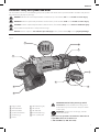 3
3
-
 4
4
-
 5
5
-
 6
6
-
 7
7
-
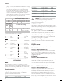 8
8
-
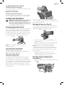 9
9
-
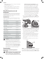 10
10
-
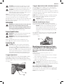 11
11
-
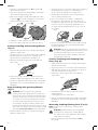 12
12
-
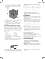 13
13
-
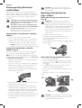 14
14
-
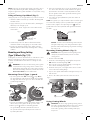 15
15
-
 16
16
-
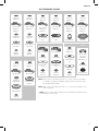 17
17
-
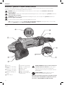 18
18
-
 19
19
-
 20
20
-
 21
21
-
 22
22
-
 23
23
-
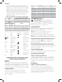 24
24
-
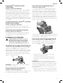 25
25
-
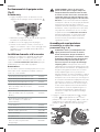 26
26
-
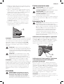 27
27
-
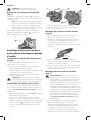 28
28
-
 29
29
-
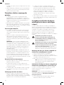 30
30
-
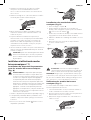 31
31
-
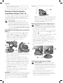 32
32
-
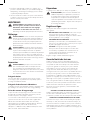 33
33
-
 34
34
-
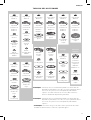 35
35
-
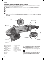 36
36
-
 37
37
-
 38
38
-
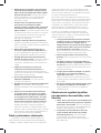 39
39
-
 40
40
-
 41
41
-
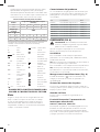 42
42
-
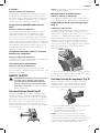 43
43
-
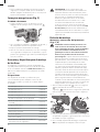 44
44
-
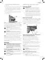 45
45
-
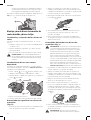 46
46
-
 47
47
-
 48
48
-
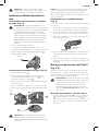 49
49
-
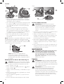 50
50
-
 51
51
-
 52
52
-
 53
53
-
 54
54
-
 55
55
-
 56
56


DeWalt 7in & 9in Large Angle Grinder DWTD28499X Owner's manual
- Category
- Power tools
- Type
- Owner's manual
Ask a question and I''ll find the answer in the document
Finding information in a document is now easier with AI
in other languages
Related papers
Other documents
-
Stanley SGS1045 User manual
-
Black & Decker G720 User manual
-
-
Stanley SSC22 User manual
-
-
Stanley SL229 User manual
-
Black & Decker G1000 Line PRO User manual
-
-
-