DeWalt DCE080D1RS User manual

Type
User manual

This manual is also suitable for

Self-Leveling Rotary Laser
DCE080RS, DCE080GS
English GB
German D
French F
Italian I
Spanish E
Português PT
Nederlands NL
Danish DK
Swedish SE
Finland FIN
Norwegian NO
Turkish TR
Greek GR
GB
NL
GR
I
FIN
D
DK
ES
NO
F
SE
PT
TR
www.2helpU.com
Figures
2
8
A
B
C
10
11
12
13
14
15
16
17
18
19
1
2
6
7
4
3
5
7
6
4
3
2
5
1
8
9
3
3V CR2430
D
DEWALT 18V 2Ah
USB
F
E
5
7
6
6
8
DW0743GS
3
1
4
2
9
10
13
11
12
7
7
14
Figures
4
4
5
6
4
DW0743GS
5/8 - 11
1
2
3
G
H
1
2
5/8-11"
I
1
2
3
2
5
GB
I
DW0743GS
< 15m
< 30m < 305m
< 30m
1
2
3
Figures
6
K
1
2
7
L
Figures
8
L
X
AA BB
L
X
A
B
M
9
L
Y
A
B
L
Y
AA BB
N
Figures
10
O
P
11
Q
2
1
4
3
5
6
7
8
4
2
3
1
8
9
S
R T
12
GB
Contents
• Laser Information
• User Safety
• Batteries and Power
• Operating Tips
• Turning the Laser On
• Checking the Calibration
• Using the Laser
• Controlling the Laser Remotely
• Accessories
• Maintenance
• Troubleshooting
• Service and Repairs
• Specications
Laser Information
The DCE080RS/GS Cordless Rotary Laser is a CLASS 2 laser
product.
EC-Declaration of Conformity
Radio Equipment Directive
DEWALT Rotary Laser
DCE080RS, DCE080GS
DEWALT hereby declares that the DEWALT Rotary Laser DC-
E080RS/DCE080GS is in compliance with the Directive 2014/53/EU
and to all applicable EU directive requirements.
The full text of the EU Declaration of Conformity can be requested
at D
EWALT Industrial Tool Co., DEWALT Europe, D-655-10 Idstein,
Germany 65509 or is available at the following internet address:
www.2helpU.com.
Search by the Product and Type Number indicated on the nameplate.
READ ALL INSTRUCTIONS
User Safety
Safety Guidelines
The denitions below describe the level of severity for each signal
word. Please read the manual and pay attention to these symbols.
DANGER: Indicates an imminently hazardous situation
which, if not avoided, will result in death or serious injury.
WARNING: Indicates a potentially hazardous situation
which, if not avoided, could result in death or serious injury.
CAUTION: Indicates a potentially hazardous situation
which, if not avoided, may result in minor or moderate injury.
NOTICE: Indicates a practice not related to personal injury which,
if not avoided, may result in property damage.
If you have any questions or comments about this or any
D
EWALT tool, go to www.2helpU.com.
WARNING:
Read and understand all instructions. Failure to follow
the warnings and instructions in this manual may result in
serious personal injury.
SAVE THESE INSTRUCTIONS
WARNING:
Laser Radiation Exposure. Do not disassemble or
modify the laser level. There are no user serviceable
parts inside. Serious eye injury could result.
WARNING:
Hazardous Radiation. Use of controls or adjustments,
or performance of procedures, other than those specied
herein may result in hazardous radiation exposure.
13
GB
The label on your laser may include the following symbols.
Symbol Meaning
V Volts
mW Milliwatts
Laser Warning
nm Wavelength in nanometers
2 Class 2 Laser
Warning Labels
For your convenience and safety, the following labels are on
your laser.
WARNING: To reduce the risk of injury, user must read
instruction manual.
WARNING: LASER RADIATION. AVOID DIRECT EYE
EXPOSURE. Class 2 Laser Product.
If the equipment is used in a manner not specied by the
manufacturer, the protection provided by the equipment may
be impaired.
Do not operate the laser in explosive atmospheres, such as
in the presence of ammable liquids, gases, or dust. This tool
may create sparks which may ignite the dust or fumes.
Store an idle laser out of reach of children and other untrained
persons. Lasers are dangerous in the hands of untrained users.
Tool service MUST be performed by qualied repair
personnel. Service or maintenance performed by unqualied
personnel may result in injury. To locate your nearest D
EWALT
service center go to www.2helpU.com.
Do not use optical tools such as a telescope or transit to view
the laser beam. Serious eye injury could result.
Do not place the laser in a position which may cause anyone
to intentionally or unintentionally stare into the laser beam.
Serious eye injury could result.
Do not position the laser near a reective surface which may
reect the laser beam toward anyone’s eyes. Serious eye injury
could result.
Turn the laser off when it is not in use. Leaving the laser on
increases the risk of staring into the laser beam.
Do not modify the laser in any way. Modifying the tool may result
in hazardous laser radiation exposure.
Do not operate the laser around children or allow children to
operate the laser. Serious eye injury may result.
Do not remove or deface warning labels. If labels are removed,
the user or others may inadvertently expose themselves to
radiation.
Position the laser securely on a level surface. If the laser falls,
damage to the laser or serious injury could result.
Personal Safety
Stay alert, watch what you are doing, and use common sense
when operating a laser product. Do not use the tool while
tired or under the influence of drugs, alcohol, or medication.
A moment of inattention while operating laser products may result
in serious personal injury.
14
GB
Use appropriate personal protective equipment, including eye
protection when working in a construction environment.
Tool Use and Care
Do not use the tool if the switch does not turn it on or off. Any
tool that cannot be controlled with the switch is dangerous and
must be repaired.
Store idle laser products out of the reach of children and do
not allow persons unfamiliar with the laser product or these
instructions to operate the laser product. Laser products are
dangerous in the hands of untrained users.
Use only accessories that are recommended by the
manufacturer for your model. Accessories that may be suitable
for one tool, may become hazardous when used with another tool.
Batteries and Power
This DeWALT rotary laser will accept all DeWALT 18 volt lithium ion
battery packs, but is built to best resist damage during a fall when
used with the following battery packs: All 1.5Ah and 2Ah
DeWALT 18
volt lithium ion batteries.
Charging the Battery Pack
The battery pack is not fully charged out of the carton. You need to
use a DeWALT 18 volt charger to charge the battery pack before you
can use the rotary laser.
Be sure to read all safety instructions before using your charger.
WARNING:
DO NOT attempt to charge the battery pack with any
chargers other than the ones listed in this manual. The
charger and battery pack are specifically designed to work
together.
WARNING:
Carefully follow all instructions and warnings on the battery
label and package and accompanying Battery Safety
Manual.
1.
Slide the battery pack into the charger as described in the
Battery Safety Manual.
2.
Wait until the battery pack is fully charged.
3.
Slide the battery pack out of the charger.
NOTE: When ordering replacement battery packs, be sure to include
the catalog number and voltage.
Installing the DeWALT 18V Battery Pack
1.
Position the fully-charged DEWALT 18V battery pack so the
release button (Figure
D
1
) is facing away from you and to the
right.
2.
Press and hold down the release button (Figure
D
1
) on the
battery pack.
3.
Slide the battery pack all the way into the track on the side of
the laser (Figure
D
2
).
4.
Release the button on the battery pack.
Removing the Battery Pack
1.
Press and hold the release button on the battery pack (Figure
D
1
).
2.
Slide the battery pack out of the track on the laser.
3.
Release the button on the battery pack.
4.
To recharge the battery pack, insert it into the charger, as
described in the Battery Safety Manual.
WARNING:
Batteries can explode or leak, and can cause injury or fire.
To reduce this risk, follow the instructions in the Battery
Safety Manual.
Storing Battery Packs
The best storage place is one that is cool and dry, and away from
direct sunlight and excess heat or cold.
Long storage will not harm the battery pack or charger. Under
proper conditions, they can be stored for 5 years or more.
SAVE THESE INSTRUCTIONS FOR FUTURE USE
15
GB
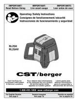
Installing the Coin Cell Battery
A coin cell battery should already be installed in the bottom of
the laser unit (Figure
D
3
) so it is ready to use the Bluetooth
®
connection, after you remove the battery protector. To remove the
battery protector on your new laser, or replace the coin cell battery in
the future, follow these steps.
1.
Carefully turn the laser upside down.
2.
On the bottom of the laser, unscrew the battery compartment
cover, which is marked 3V CR2430.
3.
Lift off the battery compartment cover and remove the coin cell
battery.
4.
If your laser is new, remove the battery protector (round disc), and
then re-insert the same coin cell battery.
5.
If your laser is not new, insert a new 3V CR2430 coin cell battery into
the battery compartment.
6.
Carefully place the battery compartment cover back in the correct
position and use the screws to secure the cover in place on the
bottom of the laser unit.
THE BLUETOOTH® WORD MARK AND LOGOS ARE REGISTERED TRADEMARKS OWNED
BY BLUETOOTH SIG, INC. AND ANY USE OF SUCH MARKS BY DEWALT IS UNDER LI-
CENSE. APPLE AND THE APPLE LOGO ARE TRADEMARKS OF APPLE INC., REGISTERED
IN THE U.S. AND OTHER COUNTRIES. APP STORE IS A SERVICE MARK OF APPLE INC.,
REGISTERED IN THE U.S. AND OTHER COUNTRIES. GOOGLE PLAY AND THE GOOGLE
PLAY LOGO ARE TRADEMARKS OF GOOGLE INC.
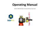
Installing Batteries in the Remote
Load new AAA batteries into the remote so you can use it with the
laser unit.
1.
On the bottom of the remote, lift up the latch to open the battery
compartment cover (Figure
C
1
).
2.
Insert two new, high-quality, name brand AAA batteries, making
sure to position the - and + ends of each battery as noted inside
the battery compartment (Figure
C
2
).
3.
Push the battery compartment cover closed until it snaps into
place (Figure
C
3
).
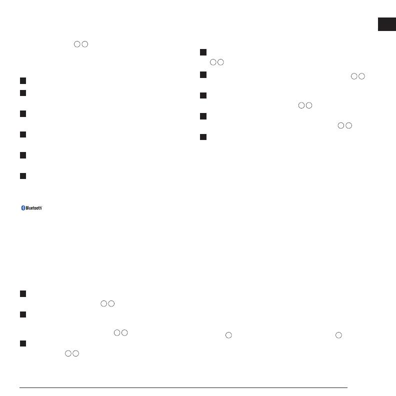
Charging the Detector
The Digital Laser Detector is powered by a Li-ion battery. To charge
the battery.
1.
Insert the USB end of the charging cable into a USB port (Figure
E
1
).
2.
On the Detector, pull the Micro USB port cover (Figure
E
2
) off
and to the side.
3.
Insert the Micro USB end of the charging cable into the
Detector's Micro USB port (Figure
E
3
).
4.
Allow the Detector time to fully-charge. The LED on the Detector
will remain Red as the battery is charging (Figure
F
13
).
5.
When the LED on the Detector turns Green, remove the
charging cable.
Operating Tips
To extend battery life per charge, turn the laser off when it is not
in use.
To ensure the accuracy of your work, check the laser calibration
often. Refer to Calibrating the Laser.
Before attempting to use the laser, make sure the tool is positioned
on a relatively smooth, secure surface.
Always mark the center of the laser line or dot. If you mark different
parts of the beam at different times you will introduce error into
your measurements.
To increase working distance and accuracy, set up the laser in the
middle of your working area.
When attaching to a tripod or wall, mount the laser securely.
When working indoors, a slow rotary head speed will produce
a visibly brighter line, a faster rotary head speed will produce
a visibly solid line.
To increase beam visibility, wear Laser Enhancement Glass es
(Figure
S
) and/or use a Laser Target Card (Figure
R
) to help find
the beam.
Extreme temperature changes can cause movement or shifting of
building structures, metal tripods, equipment, etc., which can effect
accuracy. Check your accuracy often while working.
16
GB
If the laser is dropped or has suffered a sharp blow, have the
calibration system checked by a qualified service center before
using the laser.
Turning the Laser On
1.
Insert the fully charged DEWALT 18V battery pack as shown in
Figure
D
.
2.
Gently press the power button to power ON the laser:
• The power LED indicator light (Figure
A
3
) will illuminate.
• Self-leveling mode is activated automatically and the laser unit
will self-level. Once the laser unit is level, the beam will rotate
clockwise once at 600RPM.
• 30 sec. after the last button press, HI Mode (Height of
Instrument, Anti-Drift) is activated automatically and the HI LED
(Figure
A
2
) will illuminate. (You can disable HI Mode by
holding down the Slope Mode button for 2 secs. The laser
will beep twice and the HI Mode LED will turn off. NOTE: when
HI Mode is disabled, the laser cannot detect any movement
after setup, so accuracy cannot be guaranteed.)
3.
Press (Figure
A
16
) to adjust the Rotation Speed of the
laser beam through its 4 preset speeds (150, 300, 600, and
1200 RPM). NOTE: Accuracy is best optimized at 600 RPM or
less.
4.
To change the Direction of the laser beam while in self-leveling
mode, press or (Figure
A
18
or
19
).
5.
Press the Scan Mode button
15˚/45˚/90˚
(Figure
A
17
) to set the laser
to scan in 0°, 15°, 45°, or 90° angle mode.
15˚/45˚/90˚
is used to make the laser head sweep back and forth,
creating a short, bright laser line. This short line is much
brighter and more visible than when the unit is in full rotation
mode.
• The direction of the scan zone can be controlled with the arrow
buttons
and (Figure
A
18
or
19
)
6.
If you press the Slope Mode button to turn ON Slope Mode,
the unit automatically engages the X-Axis. This allows you to
slope the laser in the direction of the X-Axis, as indicated by the
X mark on the top roll cage.
• In certain situations, it may be desirable to slope the laser in
the Y-axis. The direction of Slope Mode can be changed back
and forth between the Y-axis and the X-axis by pressing the
X-Y axis button
(Figure
A
13
).
• If using X-axis leveling, the X-axis LED (Figure
A
15
) will light,
or if using Y-axis leveling, the Y-axis LED (Figure
A
14
) will
light instead.
7.
When in Slope Mode, press or to tilt the laser head up
and down (adjust the elevation of the laser beam).
• Each quick press of
or will move the slope by 0.01º
(1/16" @ 30ft. or 1.6mm @ 10m).
• If you press and hold
or between 2 sec - 10 sec, the
slope will move from 0.01º/sec to 0.2º/sec.
• If you press and hold
or longer than 10 sec, the slope will
move 0.2º/sec.
8.
To turn off the laser unit, press and hold the power button for
3 secs.
9.
BEFORE using the laser for your first project, follow the
instructions for Checking the Calibration.
NOTE: When you press the Slope Mode button
again, the laser
will return to self-level mode.
Checking the Calibration
Field calibration checks should be done frequently. This section
provides instructions for performing simple field calibration checks of
your DeWALT Rotary Laser. Field calibration checks do not calibrate
the laser. That is, these checks do not correct errors in the leveling
or plumb capability of the laser. Instead, the checks indicate whether
or not the laser is providing a correct level and plumb line. These
checks cannot take the place of professional calibration performed
by a
DeWALT service center.
17
GB
Level Calibration Check (X-axis)
1.
Position a tripod securely on the floor between two walls that are
at least 15m apart. The exact location of the tripod is not critical.
2.
Make sure that the top of the tripod is roughly level.
• The laser will self-level only if the top of the tripod is within ±
5˚ of level.
• If the laser is set up too far out of level, it will beep when it
reaches the limit of its leveling range. No damage will be done
to the laser, but it will not operate in an “out of level” condition.
3.
Attach a tripod adapter (Figure
G
1
) to the laser unit. The
adapter may be assembled to the bottom for level mode or to
the side for plumb mode.
4.
Place the laser with the attached adapter on the tripod and
screw the threaded knob on the tripod into the female thread on
the tripod adapter.
5.
Position the laser unit with the tripod so that the laser’s X-axis
points directly toward one of the walls (Figure
L
1
).
6.
Turn the laser unit on and allow it to self-level.
7.
Where the beam appears on the left wall, mark point A, and
where the beam appears on the right wall mark point B.
8.
Turn the laser unit 180º so that the X-axis points directly toward
the opposite wall (Figure
L
2
).
9.
Allow the laser unit to self-level.
10.
Where the beam appears on the left wall, mark point AA, and
where the beam appears on the right wall mark point BB.
11.
Calculate the Total Error using the following equation:
Total Error = (AA-A) - (BB-B)
12.
If your Total Error measurement is greater than the Allowable
Error for the corresponding Distance Between Walls in the
following table, the laser must be serviced at an authorized
service center.
L (Distance Between
Walls)
Allowable Error
15m (40′) 1.5mm (3/64”)
20m (50′) 2mm (1/16”)
25m (70′) 2.5mm (3/32”)
30m (100’) 3mm (1/8”)
Level Calibration Check (Y-axis)
1.
Set up a tripod between two walls that are at least 15m apart.
The exact location of the tripod is not critical.
2.
Make sure that the top of the tripod is roughly level.
• The laser will self-level only if the top of the tripod is within ±
5˚ of level.
• If the laser is set up too far out of level, it will beep when it
reaches the limit of its leveling range. No damage will be done
to the laser, but it will not operate in an “out of level” condition.
3.
Attach a tripod adapter (Figure
G
1
) to the laser unit. The
adapter may be assembled to the bottom for level mode or to
the side for plumb mode.
4.
Place the laser with the attached adapter on the tripod and
screw the threaded knob on the tripod into the female thread on
the tripod adapter.
5.
Position the laser unit with the tripod so that the laser’s Y-axis
points directly toward one of the walls (Figure
M
1
).
6.
Turn the laser unit on and allow it to self-level.
7.
Where the beam appears on the left wall, mark point A, and
where the beam appears on the right wall mark point B.
8.
Turn the laser unit 180º so that the Y-axis points directly toward
the opposite wall (Figure
M
2
).
9.
Allow the laser unit to self-level.
10.
Where the beam appears on the left wall, mark point AA, and
where the beam appears on the right wall mark point BB.
18
GB
11.
Calculate the Total Error using the following equation:
Total Error = (AA-A) - (BB-B)
12.
If your Total Error measurement is greater than the Allowable
Error for the corresponding Distance Between Walls in the
following table, the laser must be serviced at an authorized
service center.
L (Distance Between Walls) Allowable Error
15m (40′) 1.5mm (3/64”)
20m (50′) 2mm (1/16”)
25m (70′) 2.5mm (3/32”)
30m (100’) 3mm (1/8”)
Plumb Error Check
Perform this check using a wall that is no shorter than the tallest wall
for which this rotary laser will be used (Figure
N
).
1.
Using a standard plumb bob as a reference, mark the top and
bottom of a wall. (Be sure to mark the wall and not the oor or
ceiling).
2.
Position the rotary laser securely on the oor approximately 1m
(3”) from the wall.
3.
Turn the laser on and point the laser dot at the mark on the
bottom of the wall.
4.
Using the or arrow on the Remote Control (Figure
B
6
or
7
), rotate the dot upwards.
5.
If the center of the dot scans over the mark on the top of the
wall, the laser is properly calibrated.
Using the Laser
Using the Laser on a Tripod
1.
Position a tripod securely and set it to the desired height. Make
sure that the tripod has a 5/8”-11 threaded screw to ensure
secure mounting of the laser unit.
2.
Make sure that the top of the tripod is roughly level.
• The laser will self-level only if the top of the tripod is within ±
5˚ of level.
• If the laser is set up too far out of level, it will beep when it
reaches the limit of its leveling range. No damage will be done
to the laser, but it will not operate in an “out of level” condition.
3.
Attach a tripod adapter (Figure
G
1
) to the bottom of the laser
unit (Figure
G
2
).
4.
Place the laser with the attached adapter on the tripod and
screw the threaded knob on the tripod into the female thread on
the tripod adapter.
5.
Turn the laser ON and allow it to self-level in horizontal (level)
mode (Figure
H
1
).
6.
If you want to use the laser in vertical (plumb) mode, follow
these steps while the laser is still ON:
• Carefully remove the laser unit from the tripod.
• Remove the tripod adapter (Figure
I
1
) from the bottom of
the laser unit (Figure
I
2
) and attach it to the side (Figure
I
3
).
• With the laser in the vertical (plumb) position, attach the laser
unit to the tripod (Figure
I
4
). The Dot rotates down to 6
o’clock.
• Press
to make sure the laser rotates.
7.
Adjust the rotation speed and controls, as desired (Figure
P
).
Using the Laser on a Floor
The laser level can be positioned directly on the floor for leveling and
plumbing applications such as framing walls.
1.
Place the laser on a relatively smooth and level surface where it
will not be disturbed or exposed to vibration.
2.
Position the laser for a level setting (Figure
H
1
).
3.
Turn the laser ON and allow it to self-level in horizontal (level)
mode (Figure
H
1
).
19
GB
4.
If you want to use the laser in plumb (vertical) mode, carefully
turn the laser so the keypad is at the top (Figure
H
2
). The
Dot rotates down to 6 o’clock. Press to make sure the laser
rotates.
5.
Adjust the rotation speed and controls, as desired (Figure
P
).
NOTE:
The laser will be easier to set up for wall applications if the
rotation speed is set to 0RPMs and the remote control is used
to line up the laser with control marks. The remote allows one
person to set up the laser.
Using the Laser With a Laser Detector
How the Detector works
Some laser kits include a
DeWALT Digital Laser Detector. The
DeWALT Digital Laser Detector allows you to locate a laser beam
emitted by a rotary laser in bright light conditions or over long
distances.
The detector can be used in both indoor and outdoor situations
where it is difficult to see the laser beam.
The detector is not for use with non-rotating lasers but is
compatible with most rotary red-beam (DCE080RS) and green
beam (DCE080GS) lasers.
The detector can be set to indicate the location of the beam to
either the nearest 2mm (5/64") or the nearest 1mm (3/64").
The detector gives both visual signals through the display window
(Figure
F
6
) and audio signals through the speaker (Figure
F
5
) to indicate the location of the laser beam.
Detector’s Indicators
Above
Grade
Slightly
Above
Grade
On
Grade
Slightly
Below
Grade
Below
Grade
Audible
Signal
Fast Beep Fast Beep Steady
Tone
Slow Beep Slow Beep
Display
Icon
The DEWALT Digital Laser Detector can be used with or without
the detector clamp. When used with the clamp, the detector can be
positioned on a grade rod, leveling pole, stud, or post (Figure
G
).
To connect the detector to the clamp:
• Push in the clamp latch (Figure
G
3
).
• Slide the tracks on the clamp (Figure
G
4
) around the rail on
the back of the detector (Figure
F
11
) until the button (Figure
G
5
) on the clamp snaps into the latch hole on the back of
the detector (Figure
F
12
).
• Turn the clamp knob (Figure
G
6
) counterclockwise to open
the jaws on the clamp.
• Place the clamp on the rod (Figure
G
2
) so that the detector
is positioned at the height needed to work with the laser.
• Turn the clamp knob (Figure
G
6
) clockwise to secure the
clamp on the rod.
Using the Detector
1.
Set up and position the rotary laser that you will be using
according to the manufacturer’s directions. Turn the laser on and
make sure the laser is rotating and emitting a laser beam.
2.
Press the power button once on the detector to turn the detector
on.
3.
On the bottom of the display window, notice the speaker icon
(Figure
F
10
).
To decrease the volume of the audible signal, press the volume
button (Figure
F
4
); both half circles next to the speaker icon
(Figure
F
10
) will dissappear.
• To turn off the audible signal, press the volume button (Figure
F
4
) until the speaker icon dissapears from the display
window.
20
GB
4.
On the top of the display window, view the Accuracy Mode icon
(Figure
F
8
).
indicates that the detector will give an “on grade” reading
only when the laser beam is on grade or no more than 1mm
(1/25") above or below it.
• To change the Accuracy Mode to
to have the detector
give an “on grade” reading when the laser beam is on grade
or approximately 3mm (1/8") above or below it, press the
Accuracy Mode button (Figure
F
3
) once. Then (Figure
F
9
) appears on the display window.
5.
Position the detector so that the detector window (Figure
F
14
)
is facing the laser beam produced by the rotary laser (Figure
G
).
Move the detector up or down within the approximate area of the
beam, until you have centered the detector.
6.
Use the marking notches (Figure
F
7
) to accurately mark the
position of the laser beam.
7.
To turn the detector off.
• On the detector, press
for 3 seconds.
• If a rotary laser beam does not strike the detector's beam
detection window, or if no detector buttons are pressed, within
30 minutes, the detector will shut itself off.
Controlling the Laser Remotely
You can control the laser unit remotely in either of these 3 ways:
From up to 15m away, you can use the remote to control the
laser unit (Figure
I
1
). IR sensors will maintain communication
between the remote and the laser unit.
From up to 30m away, you can use the D
EWALT
®
Tool Connect™
Application on your Bluetooth
®
device to connect to the laser unit
(Figure
I
2
).
From up to 335m away, you can control the laser unit by using
the D
EWALT
®
Tool Connect™ Application on your Bluetooth
®
device to connect to the detector that is connected to the laser unit
(Figure
I
3
). You must press the Detector button (Figure
A
6
) on the laser in order to connect the detector to the laser unit.
Controlling the Laser from up to 15m Away
The DCE080RS/GS remote control allows you to operate and set
up the laser from up to 15m away. The LED light on the remote
control (Figure
B
1
) indicates a signal is being transmitted from the
DCE080RS/GS laser unit.
You can use all the buttons on the remote's keypad to control the
laser unit. To completely power OFF a DCE080RS/GS laser unit
using the Remote keypad, press the X-Y axis button
(Figure
B
5
) and the Slope Mode button (Figure
B
2
) simultaneously.
By default, the laser unit is not paired to a remote (the laser unit is
in Public mode). LEDs on the laser unit and the remote will indicate
that they are not paired.
UNLOCKED
in Public Mode
LOCKED
in Private Mode
Description A laser is in Public Mode
if it is not paired with a
remote.
A laser is in Private
Mode if it is paired
with a remote.
A remote is in Public
Mode if it is not paired
with a laser.
A remote is in Private
Mode if it is paired
with a laser.
Control A Public laser can be
controlled by more
than one Public remote
(Figure
K
1
).
A Private laser can only
be controlled by the
remote to which it is
paired (Figure
L
).
A Public remote can
control more than one
Public laser (Figure
K
2
).
A Private remote can
only control the laser
to which it is paired
(Figure
L
).
LEDs
The unlocked
LED
will be lit on the laser
keypad (Figure
K
1
and
K
2
).
The locked
LED
on the laser will be lit
(Figure
L
).
The locked LED on the
remote will NOT be lit
(Figure
K
1
and
K
2
).
The locked LED on
the remote WILL be lit
(Figure
L
).
1 / 1

DeWalt DCE080D1RS User manual

Type
User manual
This manual is also suitable for

Ask a question and I''ll find the answer in the document

Finding information in a document is now easier with AI

Ask the document