
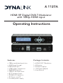
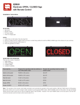
Operating Instructions
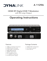
A 1127A
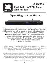
HDMI RF Digital DVB-T Modulator
with 1080p HDMI input
Package Contents
• 1080p modulated resolution
• HDMI loop through
• 1080 HDMI input
• H.264 video compression
• 30dB MER (typical)
• 100BuV ±5 output level
• RF TV antenna input
• 38-56kHz IR frequency
• 9V IR pass over RF
• Includes power supply
1 x HDMI DVB-T Modulator
1 x IR Emitter
1 x IR Receiving Eye
1 x 12V Power adapter
1 x User Manual
Features

A 1127A
HDMI RF Digital DVB-T Modulator
A high performance HD modulator for HDMI sources with IR return path
and HDMI loop through. This modulator allows you to distribute any HD
device signals (Foxtel, DVD etc) in HD around the home or business with
ease. Combined with infra-red targets and emitters full remote control
of AV devices at the location of each television is available. Ideal for
retro-tting/upgrading older analogue modulator installations.
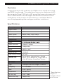
Overview
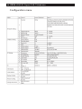
Specications
Input Channel
Video
Video System
Audio System
Source Input:
1
HDMI
480i/p, 576i/p, 720p, 1080i/p
HDMI
Video
Video Resolution
Video Bit rate
Audio
Audio Bit rate
DVB insertion tables
Compression:
1080p 25 / 30 Max
12Mbps MAX
MPEG-2 / AAC
192 Kbit/S
SDT, NIT
Service Name , Network Name , Provider
Name , TS ID , Network ID , Original NET ID,
LCN , NIT Version , Private Data ,Country
Type
Frequency
MER
Output level
RF Level Adj
Attenuation step
RF Output:
1 Multiplex DVBT with a digital TV service
177 – 858 MHz
30 dB Typically
100 dBuV ±5
0 dB ~ -20dB
1dB per step
*Specications
subject to
change without
prior notice.

A 1127A
HDMI RF Digital DVB-T Modulator
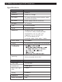
Specications
HDMI IN
HDMI OUT
RF Output
DC Switch
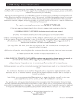
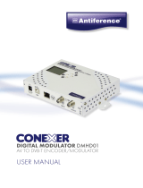
Connections:
HDMI IN
HDMI Pass Through
RF output (providing accessory power supply
9 volts DC for IR pass)
Power supply 9 volts DC for IR Pass
RF Input RF Combiner
USBF irmware upgrade
IR Out IR Emitter Output
Modulation Standard: DVBT (ETSI EN 300 744)
Constellation: QPSK, 16QAM, 64QAM
Guard Interval: 1/4, 1/8, 1/16, 1/32
Code Rate: 1/2, 2/3, 3/4, 5/6, 7/8
FFT Carriers Mode: 2K, 8K
Bandwidth: 6MHz, 7MHz, 8MHz, 7-8MHz
Power Supply 12V Adapter
Display LCD panel @ 2 x 16 characters (on front panel).
Environmental for
operating
Temperature range: 5°C - 40°C
Relative Humidity: 80% @ 30°C
Firmware upgrade
Freq. range
Insertion loss
Return path signal
freq
IR freq.
IR Receiving Eye
100 -900 MHz
3.0dB Typical
7.0MHz
HDMI
Impedance
Power consumption
75 ohm
9mA
20-60KHz

A 1127A
HDMI RF Digital DVB-T Modulator
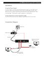
Installation
Using the Power Supply
To start using it, connect the external power supply to the 230V mains
and the 12V to the instrument input. Once connected to power, the
device turns on and it takes about 18 seconds to be operational. Then
the message “ Keyboard Locked” appears on the display.
Using a Operation via external power supply
Use only the external power adapter supplied with the instrument.
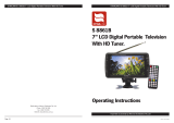
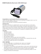
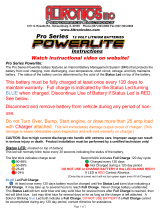
Media Player
IR Receving Eye
through RF OUT
Media Plays
Media Plays thr
ough
HDMI connection
Antenna
through RF In
IR Emitter
Connection Diagram

A 1127A
HDMI RF Digital DVB-T Modulator
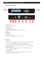
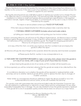
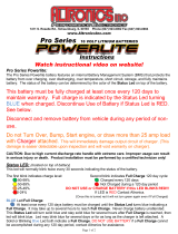
1. Display (LCD)
2. Menu navigation keys
3. IR Output
4. 9V DC Switch
5. LED (9V DC Indicator)
6. TV COFDM Output (IR Return with 9V DC)
7. RF IN
8. HDMI Out
9. HDMI In
10. USB: S/W update
11. Input 12V DC power adapter (included)
Product Overview
1
2
3 4 5 6 7 8
1. After connecting the power to the instrument, the message
“Initial….” “Please Wait...” appears for 37 seconds.
2. Then the message “Keyboard Locked” appears. To access
to the conguration menus the user has to enter a password.
3. Press ENTER.
4. The eld “Enter Password” appears. Enter the access
code. (By default: 0000).
5. Press ENTER.
6. The eld “Network Setting” appears, this is the rst option
on the conguration menu
Starting
9 10 11

A 1127A
HDMI RF Digital DVB-T Modulator
1. Frequency: It sets the frequency value for the output signal.
Important: Check that the selected frequency is not already being used
by a current television distribution channel.
2. RF Level Adj: It adjusts the power level of the output signal, in dB
units. Its range from 0 to -30 dB.
3. Bandwidth: Channel bandwidth. (6, 7 , 8 ,7-8MHz).
4. FFT Carriers: Signal transmission mode. (2K,8K).
5. Guard Interval: Safety signal margin. (1/4, 1/8, 1/16, 1/32).
6. Constellation: Constellation type used to transmit
signal(QPSK,16QAM, 64QAM).
7. Code Rate: Available values are (1/2, 2/3, 3/4, 5/6, 7/8).
8. Video Output: Video encode. H.264 of the video output.
9. Audio Output: Audio encode. Selection between MPEG-2 and AAC
10. Video Bitrate: Select video bit rate(2,4,6,8,10,12 Mbit/S).
11. Audio Bitrate: Bitrate to encode the audio. Available values are
between 192 kbit/s.
12. Service Name: Service name edit.
13. Provider Name: Service provider name edit.
14. Service ID: Service ID edit.
15. LCN: It species the index for the service sorting on the digital
terrestrial television receiver. Values are between 1 and 999.
16. Country: Country selection for LCN sorting.
17. Original Net ID: Identier of the original network. It is the number to
identify the network from where the signal comes.
18. Network ID: It is the number that identies the network where the
signal is distributed.
19. Network Name: Network name edit.
20. TS ID: It is the transport stream identier.
21. NIT Version: Network Information Table version. In some countries it
should match with other tables version received from the receiver.
22. IR: IR Frequency selection.(Mode A: 38KHz, Mode B:56KHz)
23. Information: It shows the rmware version installed in the instrument.
This option is not editable.
24. Load Default: It returns to the default values.
25. Conguration: User can backup and restore all conguration setting
from the device to a local le.
26. Change Password: It allows the user to change to a new password to
access the menu.
Conguration menu

A 1127A
HDMI RF Digital DVB-T Modulator
Conguration menu

A 1127A
HDMI RF Digital DVB-T Modulator
Altronic Distributors warrants this product for one year from date of purchase from Altronics or its resellers
to the consumer. If this item is part of an installation or another product, please contact the installer or
supplier for your warranty.
During the warranty period, we undertake to repair or replace your product at no charge if found to be
defective due to a manufacturing fault. The warranty excludes damage by misuse or incorrect installation
(i.e. failure to install and operate device according to specications in the supplied instruction manual),
neglect, shipping accident, or no fault found, nor by use in a way or manner not intended by the supplier.
For repair or service please contact your PLACE OF PURCHASE.
If this item was purchased directly from Altronics please make a warranty claim by:
1. FOR MAIL ORDER CUSTOMERS (includes school and trade orders),
a) Calling your nearest store location and quoting your tax invoice number.
b) Upon contacting Altronics, we will issue an R.A. (Return Authorisation). As Altronics have a number of
service agents throughout Australia, a copy of the R.A. will be emailed, faxed or mailed to you with full
instructions of how and where to send the goods. The freight for shipping goods back to
Altronics for all repairs is at the customers expense.
c) A copy of the R.A. form, (or at the very minimum, the R.A. number) must accompany the
goods to effect the repair.
d) Altronics will pay the return freight to the customer where the warranty claim has been accepted.
e) Please quote the R.A. number in any correspondence to us.
2. FOR OVER THE COUNTER PURCHASES to make a warranty claim, please return the goods to us in
any of our stores, with a copy of your proof of purchase (tax invoice).
a) Upon leaving the goods at one of our stores, an R.A. number will be issued to you.
b) Once repaired, you will be contacted, advising that the goods are ready to be collected from the store.
It is at Altronics discretion as to whether the goods will be repaired or replaced (whilst under warranty); and
as to whether identical goods will be used to replace the item due to changes of models / products.
Note: Under no circumstances should you attempt to repair the device yourself or via a non-authorised
Altronics service centre, as this will invalidate the warranty!
Our goods come with guarantees that cannot be excluded under the Australian Consumer Law. You are
entitled to a replacement or refund for a major failure and for compensation for any other reasonably
foreseeable loss or damage. You are also entitled to have the goods repaired or replaced if the goods fail
to be of acceptable quality and the failure does not amount to a major failure.
Distributed by Altronic Distributors Pty. Ltd.
Phone: (08) 9428 2199
altronics.com.au
Revision 16/10/2020
-
 1
1
-
 2
2
-
 3
3
-
 4
4
-
 5
5
-
 6
6
-
 7
7
-
 8
8


Dynalink A 1127A Operating instructions
- Type
- Operating instructions
- This manual is also suitable for
Ask a question and I''ll find the answer in the document
Finding information in a document is now easier with AI
Related papers
-
 Dynalink X2810 Installation guide
-
 Dynalink S8866 Operating instructions
-
 Dynalink A1129A Operating instructions
-
 Dynalink S 8862A Operating Instructions Manual
-
 Dynalink A3105 Operating instructions
-
 Dynalink S 8861B Operating Instructions Manual
-
 Dynalink A3106 Operating instructions
-
 Dynalink A3107 Operating instructions
-
 Dynalink C9034A Operating instructions
-
 Dynalink A 2704B Operating Instructions Manual


Other documents
-
 Altronics PowerTran M 8561 Operating instructions
-
 ANTIFERENCE Conexer DMHD01 User manual
-
 Altronics M 8070 Operating instructions
-
Triax MOD103T User manual
-
 Altronics PowerLite PRO SERIES Owner's manual
-
 Altronics PowerLite PRO SERIES Owner's manual
-
Typhoon 50502 Datasheet
-
Sencore OmniHub 6/16 User manual
-
-


