Page is loading ...

Autoplugin RCP-V2
Installation Manual
Rev A

1 2 3 4 5 6 7 8 9 10
X1
X2
White
1 2 3 4 5 6 7 8 9
Yellow
Grey
Black
Red
Orange
Ye llow
Brown
Blue
Additional devices control
Brown-white
Green
Green-yellow
Autoplugin RCP-V2
Red- white
Feedback to
remote control
to scheme
of turning off
Blue
Grey
Brown
Outer
indicator
to scheme
of turning on
for specialized RC
connection
Button
Figure 1
Service connector
Green
Oran ge
White-blue
Ground

3
Table of Contents
Installation procedure for plug-n-play connection……………………………….
3
Connection schemes for permanent connection ………………..………………..
3
Installation procedure for permanent connection………………...…….……...…
6
Troubleshooting…………………………………………………...……………...
7
1) Installation procedure for plug-n-play connection
· Find the service connector at the left side of the dashboard, below the
lighting control switch.
· Open the case of the service connector (if applicable).
· Pass PnP-cable wires with white connectors on the end inside the dashboard,
beside of the service connector. Pull the wires inside the dashboard.
· Connect white connectors of PnP-cable to RCP
· Connect black connector of PnP-cable to the car’s OBD-connector.
· Turn ignition on to let the module get information from CAN-bus and wait
until LED goes off. Turn ignition off.
· Check for the heater remote start by using Volvo key: turn on perimeter
lighting, then press Lock button twice.
· Find place under the dashboard for the module and fix it with adhesive tape.
· Shorten length of the cable by the strap
· Close the case of the service connector (if applicable)
Note: if you need to unplug PnP-cable from OBD-connector (ex. to connect
diagnostic equipment to the car’s electronic system), don’t pull for the wires of the
cable! Pull for the housing of connector or for the special strap (if applicable).
2) Connection schemes for permanent connection
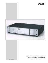
· General connection scheme (fig.1, page 2)
Explanations to the scheme:
o It is enough to connect power wires (X1.8, X1.9) and CAN-bus wires
(X2.9, X2.10) to the module to obtain a possibility to start the heater using
Volvo remote key. You can use supplied PnP-cable for such a connection.
o The car’s wiring marked in colour.
o Optional elements are outlined by dashes
· Connection of the inputs Heater_on± and Heater_off±

4
You can connect and use set of devices as a remote control of the fuel-fired heater:
specialized heater remotes (such as Telestart, EasyStart, Smart Start), additional
alarm systems remote controls, GSM mobile phones in conjunction with automotive
GSM-modules, etc.
If the remote control has output channels that give short impulses in active state, it
is possible to apply the schemes given at fig. 2-6. The remote control with two
independent channels can separately turn the heater on and off.
o The fig.3 presents the scheme to turn the heater on by the impulse of
positive polarity. The fig.4 presents the scheme to turn the heater on by
the impulse of negative polarity.
Green
Blue
X1
3
4
to RC
RCP
Ground
X1
3
4
Battery+
to RC
Green
Blue
RCP
Figure 2 Figure 3
o The fig.4 presents the scheme to turn the heater off by the impulse of
positive polarity. The fig.5 presents the scheme to turn the heater on by
the impulse of negative polarity.
White
Grey
X1
1
2
to RC
RCP
Ground
X1
1
2
Battery+
to RC
White
Grey
RCP
Figure 4 Figure 5
o The remote control with the only one output line may be connected by the
scheme at fig. 6 to add a possibility not only to turn the heater on, but also
turn the heater off too. Every one impulse on the output line of the remote
control receiver unit will move the heater to the opposite state: switch on
idle heater, switch off operated heater. To realize this mode it is necessary
to connect in pairs the inputs Heater_on+ with Heater_off+, and also the
inputs Heater_on- with Heater_off-.

5
Blue
RCP
X1
2
1
Grey
4
3
Green
White
to RC
Battery+
Figure 6
· Connection of the input RC_in
o The input RC_in is intended for connection of specialized remote controls
such as DEFA Smart Start, Hydronic Easy Start, Webasto Telestart. If
direct connection of remote control’s output line to the input RC_in is not
functional, the scheme at the fig.7 can be applied.
8586
30
87
to X1 7 of
RCP Can
.
to RC
Relay
Ground
Battery+
Figure 7
o Some GSM modules control external device by the means of inner relay.
These may be connected to RCP by the scheme at the fig.8
Battery+
GSM
to X1 7 of
RCP Can
.
Relay
Figure 8

6
· Alerts receiving
If the remote control unit has got inputs to obtain information about the heater
operation, they can be connected to the RCP’s outputs Alert_1 and Alert_2. The
outputs have negative polarity. Therefore if remote control unit not fit it, it needs to
apply a matching circuit (with relay ex.).
Events given on the outputs Alert_1 and Alert_2 are adjusted by the settings 7.3 and
7.4 accordingly. Also the output line Timer_out can be used to send notification
how much time the heater operates.
· Status output line application
1. Indication of the heater operation by the hazard warning flashers (in addition
to the direction indicators in rear-view mirrors).
The module can indicate of the heater operation by hazard flashers. Connect the
module’s output X2.2 to the grey-red wire (pin 3 of the connector) of the hazard
warning switch, and choose the settings 7.5.3 (the settings 6.2-6.7 also need to
be adjusted) for this purpose.
3)
Installation procedure for permanent connection
· General recommendations
The required tools: Torx screwdriver, wire cutter, wire stripper.
· Remove the panel around the service connector on the left side of the
dashboard
· Find place inside the dashboard to install the module (mounted on double-
sided tape)
· Connect the module to car’s wiring according to the scheme at the fig.1.
Connect the module to the receiver unit of remote control, according to the
schemes at the figures 3-9. Make task specific connections, if necessary.
The module is powered and connected to the CAN-bus wires near the service
connector using quick splice connectors (supplied).
The module’s power (pin X1.9) connects to the orange wire of service connector
(pin 16), the module’s signal ground (pin X1.8) – to the black-white wire of service
connector (pin 4).
The signal «CAN-L» (pin X2.9) connects to the violet-orange wire (pin 11), the
signal «CAN-H» (pin X2.10) – to the grey-orange wire (pin 3). Twist brown and
brown-white wires of the connector X2 to the pair before connections. It is not
recommended to lengthen these wires.

7
· Connect both connectors to the module (X2 should be connected first)
· Test the heater start from the module
· Fix the module using double-sided adhesive tape
· Install interior elements in the reverse order of removal
· Adjust the module in the programming mode if it necessary. Make notes in
the programming table of the user manual about the adjustments
4) Troubleshooting
If you have problems with module operation, first of all check indication of the
built-in LED. LED blinks on for a 10 second after powering and then has to turn off
(CAN-bus have to be awoken). If a run-time error appears at heater startup, LED
indicates an error by flashings. The number of flashes corresponds to the error code.
See table 1 for the codes description and possible solutions.
Table 1
Error
Code
Error
Description
Possible Reasons of
Error Appearance
Solutions
2
No answer
from the
heater
followed the
start
command
The heater is not
activated in the CIP
Configure the heater by Volvo
car dealer’s equipment
Outer temperature is
upper than +15 Celsius
degrees
The heater works only at
environmental temperatures
below +15°C. It is heater
manufacturer's restriction
Fuel level in the tank is
close to empty (“Fuel
Low” warning
indicator is lighting in
the CIP)
Refuel the car
The heater is blocked
after 3 unsuccessful
starts
Try to start the heater from the
CIP’s menu. If it not started to
burn, make diagnostics of the
heater.
3
Battery level
is low
The module has
determined that the
battery voltage at the
heater startup or during
the heater operation is
below the specified
settings 3.1 и 3.2
Charge car’s battery with
special charger (or start engine
to charge) or cancel 3.1/3.2
module’s settings

8
4
Time limits
exceeded
Time limit for
autonomous operation
of the heater is
achieved (with applied
setting 1.1)
Run the engine or cancel 1.1
setting
5
Unsuccessful
start
The heater was
switched off
spontaneously at
startup
Make diagnostics of the heater
if the error appears again
6
Operation
cycle too
short
The heater was
switched off
spontaneously with
operating time of less
than 20 minutes
Make diagnostics of the heater
if the error appears again
8
CAN-bus
error
The lines X2.9 и X2.10
connected incorrectly
Check the lines connection
9
Settings error
Settings have been
incorrectly stored in
RCP’s memory
Reset the settings (8.1.1),
readjust RCP
11
Heater no
connection
The heater is
unplugged from CAN-
bus or is out of order
Make diagnostics of the heater
12
Unknown
CAN-bus
CAN-bus type has not
been determined
Check for compatibility of RCP
module with the car. Try to set
the CAN-bus code manually*
* Information available on request
© Autoplugin ES www.autoplugin.ru
/