Alpine Electronics X703D A4 A4R A5 Q5 Q5R Installation guide
- Category
- Car video systems
- Type
- Installation guide

R
R
FOR CAR USE ONLY/NUR FÜR AUTOMOBILGEBRAUCH/POUR APPLICATION AUTOMOBILE
UNIQUEMENT/SOLO PARA USO EN AUTOMÓVILES/PER IL SOLO UTILIZZO IN AUTOMOBILE
EN
DE
FR
ES
IT
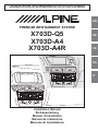
PRE
MIUM INFOTAINMENT SYSTEM
X703D-Q5
X703D-A4
X703D-A4R
Installation Manual
Einbauanleitung
Manuel d'installation
Manual de instalación
Manuale di installazione
Page is loading ...

1-EN
EN
Before installing or connecting the unit, please read
the following thoroughly for proper use.
WARNING
MAKE THE CORRECT CONNECTIONS.
Failure to make the proper connections may result in fire or product
damage.
USE ONLY IN CARS WITH A 12 VOLT NEGATIVE GROUND.
(Check with your dealer if you are not sure.) Failure to do so may
result in fire, etc.
BEFORE WIRING, DISCONNECT THE CABLE FROM THE
NEGATIVE BATTERY TERMINAL.
Failure to do so may result in electric shock or injury due to electrical
shorts.
DO NOT ALLOW CABLES TO BECOME ENTANGLED IN
SURROUNDING OBJECTS.
Arrange wiring and cables in compliance with the manual to prevent
obstructions when driving. Cables or wiring that obstruct or hang up
on places such as the steering wheel, shift lever, brake pedals, etc. can
be extremely hazardous.
DO NOT SPLICE INTO ELECTRICAL CABLES.
Never cut away cable insulation to supply power to other equipment.
Doing so will exceed the current carrying capacity of the wire and
result in fire or electric shock.
DO NOT DAMAGE PIPE OR WIRING WHEN DRILLING
HOLES.
When drilling holes in the chassis for installation, take precautions so
as not to contact, damage or obstruct pipes, fuel lines, tanks or
electrical wiring. Failure to take such precautions may result in fire.
DO NOT USE BOLTS OR NUTS IN THE BRAKE OR
STEERING SYSTEMS TO MAKE GROUND CONNECTIONS.
Bolts or nuts used for the brake or steering systems (or any other
safety-related system), or tanks should NEVER be used for
installations or ground connections. Using such parts could disable
control of the vehicle and cause fire etc.
KEEP SMALL OBJECTS SUCH AS BATTERIES OUT OF
THE REACH OF CHILDREN.
Swallowing them may result in serious injury. If swallowed, consult a
physician immediately.
DO NOT INSTALL IN LOCATIONS WHICH MIGHT HINDER
VEHICLE OPERATION, SUCH AS THE STEERING WHEEL
OR SHIFT LEVER.
Doing so may obstruct forward vision or hamper movement etc. and
results in serious accident.
DO NOT OBSTRUCT AIRBAGS OR ANY OTHER SAFETY
RELEVANT PARTS OF THE VEHICLE WHILE INSTALLING
THE PRODUCT.
Doing so may lead to failure of the vehicle's safety systems and
results in severe injury or death. If you are unclear where such parts
are located, please review your car's user manual or contact your car
manufacturer.
CAUTION
HAVE THE WIRING AND INSTALLATION DONE BY
EXPERTS.
The wiring and installation of this unit requires special technical skill
and experience. To ensure safety, always contact the dealer where you
purchased this product to have the work done.
USE SPECIFIED ACCESSORY PARTS AND INSTALL THEM
SECURELY.
Be sure to use only the specified accessory parts. Use of other than
designated parts may damage this unit internally or may not securely
install the unit in place. This may cause parts to become loose
resulting in hazards or product failure.
ARRANGE THE WIRING SO IT IS NOT CRIMPED OR
PINCHED BY A SHARP METAL EDGE.
Route the cables and wiring away from moving parts (like the seat
rails) or sharp or pointed edges. This will prevent crimping and
damage to the wiring. If wiring passes through a hole in metal, use a
rubber grommet to prevent the wire's insulation from being cut by the
metal edge of the hole.
DO NOT INSTALL IN LOCATIONS WITH HIGH MOISTURE
OR DUST.
Avoid installing the unit in locations with high incidence of moisture
or dust. Moisture or dust that penetrates into this unit may result in
product failure.
PRECAUTIONS
• Be sure to disconnect the cable from the (–) battery post before
installing your X703D. This will reduce any chance of damage to
the unit in case of a short-circuit.
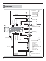
• Be sure to connect the colour
coded leads according to the diagram.
Incorrect connections may cause the unit to malfunction or damage
to the vehicle's electrical system.
• When making connections to the vehicle's electrical system, be
aware of the factory installed components (e.g. on-board
computer). Do not tap into these leads to provide power for this
unit. When connecting the X703D to the fuse box, make sure the
fuse for the intended circuit of the X703D has the appropriate
amperage. Failure to do so may result in damage to the unit and/or
the vehicle. When in doubt, consult your Alpine dealer.
WARNING
Page is loading ...
Page is loading ...
Page is loading ...
Page is loading ...
Page is loading ...

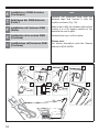
3
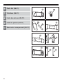
EN
to fix the display
(Audi
Q5)
DE
M5 x 8 mm (4 x) zur
Befestigung der
A
VN-Einheit
9 Schrauben
M5 x 8 mm (4 x) zur
Befestigung des
Displays (Audi Q5)
(X703D)
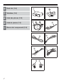
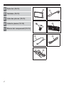
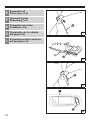
1 AVN Unit
1a
Mounting clip
2,
2a
,
2b
GPS Antenna set
3 PRE OUT cable
harness
4 USB Extension cable
5 Remote cable harness
6 AUX cable harness
7 Display power harness
8 Screws
M5 x 8 mm (4x)
to fix the AVN Unit
9 Screws M5 x 8 mm (4x)
(X703D)
1 AVN-Einheit
1a
Befestigungsclip
2,
2a
,
2b
GPS-Antennenset
3 PRE OUT-Kabelbaum
4 USB-Verlängerungs
kabel
5 Fernbedienungs-
Kabelbaum
6 AUX-Kabelbaum
7 Kabelbaum der Display-
Stromversorgung
8 Schrauben
FR
fixation de l'écran
(Audi
Q5)
ES
p
ara fijar la pantalla
(Audi Q5)
(X703D)
1 Ensemble AVN
1a
Agrafe de fixation
2,
2a
,
2b
Ensemble de
l'antenne GPS
3 Faisceau PRE OUT
4 Câble d'extension USB
5 Faisceau de la
télécommande
6 Faisceau auxiliaire
7 Faisceau d'alimentation
de l'écran
8 VisM5x 8mm (4x)
de fixation de
l'ensemble AVN
9 VisM5x 8mm (4x) de
(X703D)
1 Unidad AVN
1a
Pinza de montaje
2,
2a
,
2b
J
uego de la
antena GPS
3 Arnés de cables
PRE OUT
4 Prolongador USB
5 Arnés de cables
remotos
6 Arnés de cables AUX
7 Arnés de alimentación
de la pantalla
8 Tornillos M5 x 8 mm (x4)
para fijar la unidad AVN
9 Tornillos M5 x 8 mm (x4)
IT
il fissaggio del display
(Audi
Q5)
(X703D)
1 Unità AVN
1a
Fermaglio di fis
saggio
2,
2a
,
2b
Kit antenna GPS
3 Cablaggio PRE OUT
4 Cavo di prolunga USB
5 Cablaggio comando
remoto
6 Cablaggio AUX
7 Cablaggio
alimentazione display
8 Viti M5 x 8 mm (4x) per
il fissaggio dell'unità
AVN
9 Viti M5 x 8 mm (4x) per
Page is loading ...
Page is loading ...
Page is loading ...

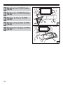
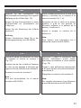
7
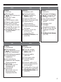
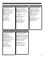
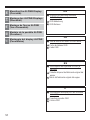
EN
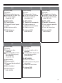
(KCX-V100-A)
^ CAN Interface box
& Protection cushion for
CAN Interface box
* Power cable harness
( CAN Interface cable
harness
(DVE-5300X)
*Optional
) DVD Player
Screws M5 x 8 mm (4x)
to fix the DVD Player
Mounting clip
HDMI cable
= DVD Power cable
harness
q Remote control
DE
(KCX-V100-A)
^ CAN-Interface-Terminal
& Schutzpolster für
CAN-Interface-Terminal
* Kabelbaum der
Stromversorgung
( CAN-Interface-
Kabelbaum
(DVE-5300X)
*optional
) DVD-Player
Schrauben M5 x 8 mm
(4 x) zur Befestigung
des DVD-Players
Befestigungsclip
HDMI-Kabel
= Kabelbaum der
DVD-Stromversorgung
q Fernbedienung
20a
20b
21
20a
20b
21
FR
(KCX-V100-A)
^ Boîtier d'interface CAN
& Coussin de protection
du boîtier d'interface
CAN
* Faisceau d'alimentation
( Faisceau de l'interface
CAN
(DVE-5300X)
*Option
) Lecteur DVD
VisM5x8mm (4x) de
fixation du lecteur DVD
Agrafe de fixation
Câble HDMI
= Faisceau d'alimentation
du lecteur DVD
q Télécommande
ES
(KCX-V100-A)
^ Caja de la interfaz CAN
& Almohadilla protectora de
la caja de la interfaz CAN
* Arnés de los cables de
alimentación
( Arnés de los cables de
la interfaz CAN
(DVE-5300X)
*Opcional
) Reproductor de DVD
Tornillos M5 x 8 mm (x4)
para fijar el reproductor
de DVD
Pinza de montaje
Cable HDMI
= Arnés de los cables del
DVD
q Mando a distancia
20a
20b
21
20a
20b
21
IT
(KCX-V100-A)
^ Scatola di interfaccia
CAN
& Tappetino di protezione
per scatola di interfaccia
CAN
* Cablaggio di
alimentazione
( Cablaggio interfaccia
CAN
(DVE-5300X)
*Optional
) Lettore DVD
Viti M5 x 8 mm (4x) per il
fissaggio del lettore DVD
Fermaglio di fissaggio
Cavo HDMI
= Cablaggio
alimentazione DVD
q Telecomando
20a
20b
21
Page is loading ...

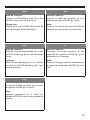
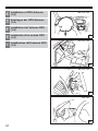
9
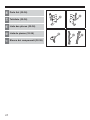
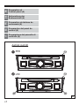
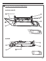
EN
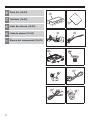
For Audi A4, Audi A5:
w Panel cover
Screws M4 x 8 mm (8x)
, Protection strips
e Bracket LCD BKT A
r Bracket LCD BKT B
Bracket left
y Bracket right
For Audi Q5:
u Panel cover
i Bracket left
o Bracket right
DE
Für Audi A4, Audi A5:
w Abdeckung
Schrauben
M4 x 8 mm (8 x)
, Schutzleisten
e Halterung LCD BKT A
r Halterung LCD BKT B
Halterung links
y Halterung rechts
Für Audi Q5:
u Abdeckung
i Halterung links
o Halterung rechts
24a
24b
24c
27
24a
24b
24c
27
FR
Pour Audi A4, Audi A5 :
w Cache du tableau
VisM4x8mm (8x)
, Bandes de protection
e Support écran LCD
BKT A
e Support écran LCD
BKT B
Support gauche
y Support droit
Pour Audi Q5 :
u Cache du tableau
i Support gauche
o Support droit
ES
Para Audi A4 y Audi A5:
w Cubierta del panel
Tornillos M4 x 8 mm (x8)
, Bandas de protección
e Soporte para LCD BKT A
r Soporte para LCD BKT B
Soporte izquierdo
y Soporte derecho
Para Audi Q5:
u Cubierta del panel
i Soporte izquierdo
o Soporte derecho
24a
24b
24c
27
24a
24b
24c
27
IT
Per Audi A4, Audi A5:
w Copertura pannello
Viti M4 x 8 mm (8x)
, Nastri di protezione
e Staffa LCD BKT A
r Staffa LCD BKT B
Staffa sinistra
y Staffa destra
Per Audi Q5:
u Copertura pannello
i Staffa sinistra
o Staffa destra
24a
24b
24c
27
Page is loading ...

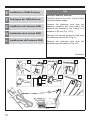
11
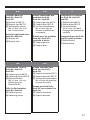
EN
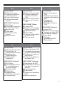
Common parts for
Audi A4, Audi A5,
Audi Q5:
p Bracket left BKT-L
[ Bracket right BKT-R
] Self-tapping screws
M4 x 8 mm (4x) to fix
the Control panel
Parts for right-hand drive
Audi A4, Audi A5:
\ Bracket left
a Bracket right
DE
Gemeinsame Teile für
Audi A4, Audi A5,
Audi Q5:
p Halterung links BKT-L
[ Halterung rechts BKT-R
] Blechschrauben
M4 x 8 mm (4 x) zur
Befestigung der
Bedieneinheit
Teile für Rechtslenker
Audi A4, Audi A5:
\ Halterung links
a Halterung rechts
FR
Pièces communes aux
modèles Audi A4,
Audi A5, Audi Q5 :
p Support gauche BKT-L
[ Support droit BKT-R
] Vis auto-taraudeuses
M4 x 8 mm (4x) de
fixation du tableau de
commande
Pièces pour les modèles
Audi A4, Audi A5 à
conduite à droite :
\ Support gauche
a Support droit
ES
Piezas comunes para
Audi A4, Audi A5 y
Audi Q5:
p Soporte izquierdo BKT-L
[ Soporte derecho BKT-R
] Tornillos autoenroscables
M4 x 8 mm (x4) para fijar
el panel de control
Piezas para Audi A4 y
Audi A5 con volante a la
derecha:
\ Soporte izquierdo
a Soporte derecho
IT
Componenti in comune
per Audi A4, Audi A5,
Audi Q5:
p Staffa sinistra BKT-L
[ Staffa destra BKT-R
] Viti autofilettanti
M4 x 8 mm (4x) per il
fissaggio del pannello di
controllo
Componenti per Audi A4,
Audi A5 guida a destra:
\ Staffa sinistra
a Staffa destra
Page is loading ...

13
EN
s Plastic wedge
d Screwdriver Torx 20
f Screwdriver PH1
g Screwdriver flat
h Socket key 8 mm
j Wrench with width
across flats 10
k Pullout hook
DE
s Kunststoffkeil
d
Torx-Schraubendreher 20
f Schraubendreher PH1
g Flachschlitz-
Schraubendreher
h Steckschlüssel 8 mm
j Schraubenschlüssel mit
Schlüsselweite 10
k Ausziehhaken
FR
s Cale en plastique
d Tournevis Torx 20
f Tournevis PH1
g Tournevis plat
h Clé à douille 8 mm
j Clé plate de 10
k Crochet d'extraction
ES
s Cuña de plástico
d Destornillador Torx 20
f Destornillador PH1
g Destornillador plano
h Llave tubular de 8 mm
j Llave con distancia
entre caras de 10
k Gancho de extracción
IT
s Cuneo di plastica
d Cacciavite Torx 20
f Cacciavite PH1
g Cacciavite a punta piatta
h Chiave a bussola da
8mm
j Chiave con larghezza di
chiave 10
k Gancio estrattore

14
EN
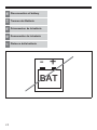
Disconnection of battery
DE
Trennen der Batterie
FR
Déconnexion de la batterie
ES
Desconexión de la batería
IT
Distacco della batteria
BAT
- +

15
EN
WARNING:
Make sure to disconnect the cable from
the negative battery terminal before
proceeding.
In case of automatic vehicles, the gear
shift lever must be set to D.
The battery of the vehicle is located under
the carpet floor of the trunk.
DE
WARNUNG:
Entfernen Sie das Kabel vom Minuspol der
Batterie, bevor Sie fortfahren.
Bei Automatikfahrzeugen muss der Schalt-
hebel auf D gesetzt werden.
Die Batterie des Fahrzeugs befindet sich
unter dem Bodenteppich im Kofferraum.
FR
AVERTISSEMENT :
N'oubliez pas de débrancher le câble de la
borne négative de la batterie avant toute
chose.
Pour les véhicules automatiques, le levier
de vitesses doit être placé en position D.
La batterie du véhicule se trouve sous le
tapis de sol du coffre.
ES
ADVERTENCIA:
Antes de proceder, asegúrese de
desconectar el cable del terminal negativo
de la batería.
En el caso de los vehículos automáticos,
la palanca de cambios debe estar en la
posición D.
La batería del vehículo está ubicada bajo
la alfombra del suelo del maletero.
IT
AVVERTIMENTO:
Prima di procedere, ricordare di scollegare
il cavo dal terminale negativo della
batteria.
In caso di veicoli con cambio automatico,
portare il selettore in posizione D.
La batteria del veicolo è posizionata sotto il
pianale moquettato del bagagliaio.

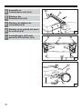
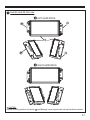
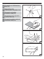
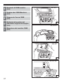
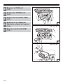
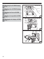
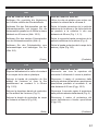
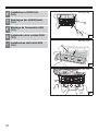
16
EN
Preparation of
Control panel (1-3)
DE
Vorbereitung der
Bedieneinheit (1-3)
FR
Préparation du tableau de
commande (1-3)
ES
Preparación del panel de
control (1-3)
IT
Preparazione del pannello di
controllo (1-3)
@
1
@
2
@
3

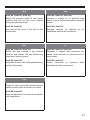
17
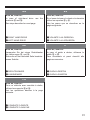
EN
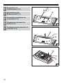
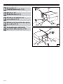
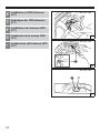
* OPTIONAL DVD PLAYER
Skip this step if optional DVD Player ) is
not installed.
Audi A4, Audi A5, Audi Q5:
Loosen the 3 screws to remove the
opening cover as shown.
DE
* OPTIONALER DVD-PLAYER
Überspringen Sie diesen Schritt, wenn der
optionale DVD-Player ) nicht installiert ist.
Audi A4, Audi A5, Audi Q5:
Lösen Sie die 3 Schrauben, um die
Öffnungsabdeckung gemäß Abbildung zu
entfernen.
FR
* LECTEUR DVD EN OPTION
Ignorez cette opération si le lecteur DVD )
en option n'est pas installé.
Audi A4, Audi A5, Audi Q5 :
Desserrez les 3 vis pour détacher le cache
de la fente (voir l'illustration).
ES
* REPRODUCTOR DE DVD OPCIONAL
Sáltese este paso si no tiene instalado el
reproductor de DVD opcional ).
Audi A4, Audi A5, Audi Q5:
Afloje los 3 tornillos para retirar la cubierta
de apertura tal como se muestra.
IT
* LETTORE DVD OPTIONAL
Se il lettore DVD ) optional non è
presente, saltare questo passo.
Audi A4, Audi A5, Audi Q5:
Allentare le 3 viti per togliere la copertura
dello slot, come mostrato.

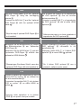
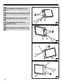
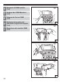
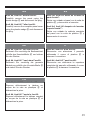
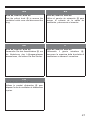
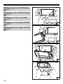
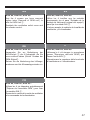
18
EN
Preparation of
Control panel (4)
DE
Vorbereitung der
Bedieneinheit (4)
FR
Préparation du tableau de
commande (4)
ES
Preparación del panel de
control (4)
IT
Preparazione del pannello di
controllo (4)
@
@
a\
1
2
RHD
Audi A4, Audi A5
LHD
4

19
EN
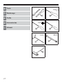
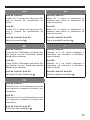
Audi A4, Audi A5:
In case of right-hand drive use the
brackets \ and a.
See steps described on next page.
1 RIGHT HAND DRIVE
2 LEFT HAND DRIVE
DE
Audi A4, Audi A5:
Verwenden Sie bei einem Rechtslenker
die Halterungen \ und a.
Siehe die auf der nächsten Seite beschrie-
benen Schritte.
1 RECHTSLENKER
2 LINKSLENKER
FR
Audi A4, Audi A5 :
Pour un véhicule avec conduite à droite,
utilisez les supports \ et a.
Voir les opérations décrites à la page
suivante.
1 CONDUITE À DROITE
2 CONDUITE À GAUCHE
ES
Audi A4, Audi A5:
En el caso de tener el volante a la derecha
utilice los soportes \ y a.
Vea los pasos que se describen en la
página siguiente.
1 VOLANTE A LA DERECHA
2 VOLANTE A LA IZQUIERDA
IT
Audi A4, Audi A5:
In caso di guida a destra, utilizzare le
staffe \ e a.
Fare riferimento ai passi descritti alla
pagina successiva.
1 GUIDA A DESTRA
2 GUIDA A SINISTRA

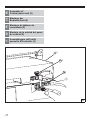
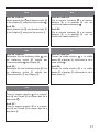
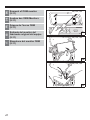
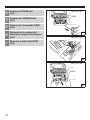
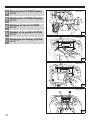
20
EN
Preparation of
Control panel (5-7)
DE
Vorbereitung der
Bedieneinheit (5-7)
FR
Préparation du tableau de
commande (5-7)
ES
Preparación del panel de
control (5-7)
IT
Preparazione del pannello di
controllo (5-7)
@
5
@
6
@
7

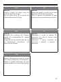
21
EN
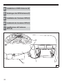
Audi A4, Audi A5:
Loosen the 6 screws to remove the cover
of the backside from the Control panel @.
Change the existing brackets with brackets
\ and a as shown.
DE
Audi A4, Audi A5:
Lösen Sie die 6 Schrauben, um die
Abdeckung von der Rückseite der
Bedieneinheit @ abzunehmen.
Ersetzen Sie die vorhandenen Halterungen
gemäß Abbildung durch die Halterungen \
und a.
FR
Audi A4, Audi A5 :
Desserrez les 6 vis pour déposer le cache
à l'arrière du tableau de commande @.
Remplacez les supports existants \ et a
(voir l'illustration).
ES
Audi A4, Audi A5:
Afloje los 6 tornillos para retirar la cubierta
de la parte posterior del panel de control @.
Cambie los soportes existentes por el \ y
el a tal como se muestra.
IT
Audi A4, Audi A5:
Allentare le 6 viti per rimuovere la copertura
dal retro del pannello di controllo @.
Sostituire le staffe presenti con quelle \ e
a, come illustrato.

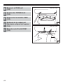
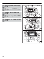
22
EN
Assembly of
Control panel unit (1-2)
DE
Montage der
Bedieneinheit (1-2)
FR
Montage du tableau de
commande (1-2)
ES
Montaje de la unidad del panel
de control (1-2)
IT
Assemblaggio dell'unità
pannello di controllo (1-2)
*
*
)
8
1[
2
0
a
1
*
*
)
1 p8
2
0
a
2

23
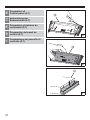
EN
Attach BKT-L p and BKT-R [ to the AVN
Unit 1 and the *optional DVD Player )
with screws 8 and .
Please note:
Max. allowed power to fix screws is
1,6 Nm.
* Skip this step if optional DVD Player ) is
not installed.
DE
Bringen Sie BKT--L p und BKT-R [
mithilfe der Schrauben 8 und an der
AVN-Einheit 1 und dem *optionalen
DVD-Player ) an.
Achtung:
Das max. zulässige Drehmoment für das
Anziehen der Schrauben beträgt 1,6 N·m.
* Überspringen Sie diesen Schritt, wenn der
optionale DVD-Player ) nicht installiert ist.
FR
Fixez les supports BKT-L p et BKT-R [
sur l'ensemble AVN 1 et le lecteur DVD
en option* ) avec les vis 8 et .
Note :
Le couple de serrage maximal des vis est
égal à 1,6 N·m.
* Ignorez cette opération si le lecteur
DVD ) en option n'est pas installé.
20a
20a
20a
ES
Fije el BKT-L p y el BKT-R [ a la unidad
AVN 1 y al reproductor de DVD opcional*
) con los tornillos 8 y .
Nota:
La fuerza máxima permitida para fijar los
tornillos es de 1,6 N·m.
* Sáltese este paso si no tiene instalado el
reproductor de DVD opcional ).
IT
Fissare le staffe BKT-L p e BKT-R [
all'unità AVN 1 e al lettore DVD *optional
) con le viti 8 e .
Nota:
La coppia massima ammessa per il
serraggio delle viti è 1,6 Nm.
* Se il lettore DVD optional ) non è
presente, saltare questo passo.
20a
20a

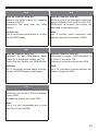
24
EN
Assembly of
Control panel unit (3-5)
DE
Montage der
Bedieneinheit (3-5)
FR
Montage du tableau de
commande (3-5)
ES
Montaje de la unidad del panel
de control (3-5)
IT
Assemblaggio dell'unità
pannello di controllo (3-5)
EXT.KEY
#
1
p
3
@
#
4
@
#
$
5

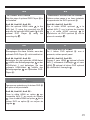
25
EN
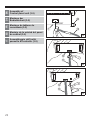
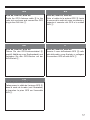
Connect the AVN Unit 1 and the Control
panel @ with the external Control panel
cable #.
Connect the Microphone cable $ with the
Control panel @.
DE
Verbinden Sie die AVN-Einheit 1 und die
Bedieneinheit @ mithilfe des externen
Bedieneinheit-Kabels #.
Schließen Sie das Mikrofonkabel $ an die
Bedieneinheit @ an.
FR
Connectez l'ensemble AVN 1 et le
tableau de commande @ au câble externe
du tableau de commande #.
Connectez le câble du micro $ au tableau
de commande @.
ES
Conecte la unidad AVN 1 y el panel de
control @ con el cable externo del panel
de control #.
Conecte el cable del micrófono $ al panel
de control @.
IT
Collegare l'unità AVN 1 e il pannello di
controllo @ al cavo esterno # del
pannello di controllo.
Collegare il cavo $ del microfono al
pannello di controllo @.

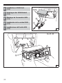
26
EN
Assembly of
Control panel unit (6-8)
DE
Montage der
Bedieneinheit (6-8)
FR
Montage du tableau de
commande (6-8)
ES
Montaje de la unidad del panel
de control (6-8)
IT
Assemblaggio dell'unità
pannello di controllo (6-8)
*
)
@
6
p
[
]
]
@
7
HDMI Out
HDMI In
*
*
-
)
1
8
Page is loading ...
Page is loading ...
Page is loading ...
Page is loading ...
Page is loading ...
Page is loading ...
Page is loading ...
Page is loading ...
Page is loading ...
Page is loading ...
Page is loading ...
Page is loading ...
Page is loading ...
Page is loading ...
Page is loading ...
Page is loading ...
Page is loading ...
Page is loading ...
Page is loading ...
Page is loading ...
Page is loading ...
Page is loading ...
Page is loading ...
Page is loading ...
Page is loading ...
Page is loading ...
Page is loading ...
Page is loading ...
Page is loading ...
Page is loading ...
Page is loading ...
Page is loading ...
Page is loading ...
Page is loading ...
Page is loading ...
Page is loading ...
Page is loading ...
Page is loading ...
Page is loading ...
Page is loading ...
Page is loading ...
Page is loading ...
Page is loading ...
Page is loading ...
Page is loading ...
Page is loading ...
Page is loading ...
Page is loading ...
Page is loading ...
Page is loading ...
Page is loading ...
Page is loading ...
Page is loading ...
Page is loading ...
Page is loading ...
Page is loading ...
Page is loading ...
Page is loading ...
Page is loading ...
Page is loading ...
-
 1
1
-
 2
2
-
 3
3
-
 4
4
-
 5
5
-
 6
6
-
 7
7
-
 8
8
-
 9
9
-
 10
10
-
 11
11
-
 12
12
-
 13
13
-
 14
14
-
 15
15
-
 16
16
-
 17
17
-
 18
18
-
 19
19
-
 20
20
-
 21
21
-
 22
22
-
 23
23
-
 24
24
-
 25
25
-
 26
26
-
 27
27
-
 28
28
-
 29
29
-
 30
30
-
 31
31
-
 32
32
-
 33
33
-
 34
34
-
 35
35
-
 36
36
-
 37
37
-
 38
38
-
 39
39
-
 40
40
-
 41
41
-
 42
42
-
 43
43
-
 44
44
-
 45
45
-
 46
46
-
 47
47
-
 48
48
-
 49
49
-
 50
50
-
 51
51
-
 52
52
-
 53
53
-
 54
54
-
 55
55
-
 56
56
-
 57
57
-
 58
58
-
 59
59
-
 60
60
-
 61
61
-
 62
62
-
 63
63
-
 64
64
-
 65
65
-
 66
66
-
 67
67
-
 68
68
-
 69
69
-
 70
70
-
 71
71
-
 72
72
-
 73
73
-
 74
74
-
 75
75
-
 76
76
-
 77
77
-
 78
78
-
 79
79
-
 80
80
-
 81
81
-
 82
82
-
 83
83
-
 84
84
-
 85
85
-
 86
86
-
 87
87
-
 88
88
-
 89
89
-
 90
90
-
 91
91
-
 92
92


Alpine Electronics X703D A4 A4R A5 Q5 Q5R Installation guide
- Category
- Car video systems
- Type
- Installation guide
Ask a question and I''ll find the answer in the document
Finding information in a document is now easier with AI
in other languages
Related papers
-
Alpine X701D A4 A4R Q5 User manual
-
Alpine Electronics X902D-DU User manual
-
Alpine X901D-DU User manual
-
-
-
 Mode d'Emploi X703D A4 A4R A5 Q5 Q5R User manual
-
-
 Mode d'Emploi INE-W720D Installation guide
-
 Mode d'Emploi INE-F904D Installation guide
-
Alpine iLX-700 Owner's manual


Other documents
-
Alpine KCX-630HD Owner's manual
-
Alpine SWE-1200 Owner's manual
-
-
-
-
-
-
Albrecht Aktive DAB+ Scheiben-Folienantenne SMB DR54 / DR56+ / DR56C / DR57 Owner's manual
-
Hama 00080871 Owner's manual
-
Alpine HCE-C105 - Rear View Camera System User manual