Page is loading ...

_____________________________________________________________
OLYMPIA UHF antennas AOI 65 212340
AON 65 212344
AOP 65 212348
__________________________________________________________________________________
General safety instructions
Please read the following safety instructions carefully and thoroughly
before you start installing the antenna, and keep observing them
during the installation.
The installation of the antenna demands a high degree of responsibility for
yourself and other people. For this reason, the installation must be executed by
an electrician (expert on his/her trade). In order to assist you, some important
safety instructions have been compiled in the following. However, these instruc-
tions are not exhaustive, as we are not aware of the local conditions.
1. Do not use the antenne for purposes other than intended by the manufacturer.
2. Only use the components as prescribed by the manufacturer and do not
modify them.
3. ATTENTION! DANGER TO LIFE!
4. When selecting the antenna site, you must consider the structural
characteristics of the building. Installation on the edge of rooftops or
buildings and on cylindrical structures could lead to increased wind loads and
vibration stress according to DIN 1055, part 4, or DIN 4131.
Non-observance of these instructions may cause exceeding of the load limit
or the vibration resistance.
5. Do not install the antenna on buildings with easily inflammable materials as rooftop, such as straw, reed or
similar materials.
6. Only step on firm, dry rooftops and protect yourself against falling down.
7. Ladders, scaffoldings, safety belts etc. must be in good order.
8. Passers-by must not be endangered by falling objects. Secure the work/danger area.
9. Mind that the technical values (e.g. wind load) of the antenna mast are not exceeded. Refer to the
manufacturer if you do not know these values. Find an overview of the masts offered by Kathrein on the last
page.
10. Mount the antenna mast on solid ground only (walls, concrete, rafters) using the clamps, dowels and screws
recommended by the manufacturer.
11. Immediately leave the roof in case of a thunderstorm!
12. Ground the antenna installation according to EN 50083-1.
Notice:
The OLYMPIA UHF antennas were designed solely for the limited purpose of receiving terrestrial TV
signals and as indoor antennas. Under the terms of DIN 4131, an antenna is reckoned an indoor antenna if
the mast length does not exceed 6 metres and if the torque needed for screwing the antenna is at 1,650 Nm
at maximum.
Do never mount an antenna under power supply
lines! Touching power supply lines with parts of
your body, with antenna parts or tools may cause
an electrical shock or serious burns.
936.2595/B/1104/1.4e
Suitable for
DVB-T (B IV/V)
AOI 65
AON 65
AOP 65

_____________________________________________________________
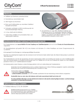
Mast installation and mast calculation (Fig. 1)
- Make sure that the mast is in vertical position when mounting it
- Only use masts or standpipes specially designed for antenna
installation. Other tubes mostly do not have the necessary
stability to withstand heavy wind or other climatical situations.
Kathrein-masts and clamps fulfil these requirements.
Find an overview of the masts provided by Kathrein on the last
page
- The clampling range of the mast clamp of the OLYMPIA
antennas is from 22 mm to 60 mm
- If the mast is to be mounted on a roof, you have to clamp at least
1/6 of its length
- Mind that the mast holders (e.g. clamps) are mounted on solid
ground (wood, concrete, walls)
Installing several antennas on one mast
Never exeed the maximum load capacity of the mast or clamps
when mounting several antennas on one mast.
Antenna installation (Fig. 2)
1. If necessary, plug together the antenna parts, and fix them using
wing screws.
2. Fix the dipole with cable connection box on the antenna square
pipe using a knurled screw.
3. Open the reflector grille and fix it with the wing screws through
the antenna square pipe.
4. Open the mast clamp and fix the antenna on the mast.
Slightly screw the wing nuts on the mast clamp so that you
are able to align the antenna to optimum reception.
936.2595/B/1104/2.4e
Fig. 1
Fig. 2

_____________________________________________________________
Connection of the cable (Fig. 3-4)
1. Unscrew the knurled screw on the cable connection box and
lift the cap
2. Skin the cable
3. Open the cable connection clamp and the strain relief clamp
in the cap
4. Connect the cable and tighten the clamps
5. Screw the cap on the connection box
6. Lay the cable according to the local conditions so that it cannot flutter in the wind and chafe (use either cable
clamps or cable ties or insulating tape)
7. In order to avoid ingress of moisture in the mast or brickwork, make a 'water sack' with the cable (Fig. 4)
Antenna alignment
Align the antenna for optimum reception by turning it. If necessary, use an antenna measurement device. Select
any programme on the TV set or the measurement device for the antenna alignment.
After finishing the alignment, tighten the wing screws on the mast clamp.
Indication of the reception of DVB-T signals
Kathrein antennas are pre-assembled for the reception of horizontally polarised signals. However, DVB-T signals
are also transmitted in vertical polarisation.
For DVB-T reception, turn the antenna in its longitudinal alignment to the transmitter rotated 90° counter-clockwise.
Observe the direction of rotation, as otherwise moisture can ingress in the connection box through the cable entry.
If the antenna was properly mounted, the cable outlet points slantwise down, and the Kathrein-writing is legible
horizontally-aligned (Fig. 6). If not, the Kathrein-writing is upside-down.
Safety instruction:
Mounting steps
The following steps must be carried out in order to be able to mount the antenna on the mast so that vertically
polarised signals can be received:
1. Unfasten the mast clamp from the axle tube by loosening the clamping screw
2. Pull off the mast clamp
3. Rotate the clamp 90° clockwise
4. Slide the mast clamp on the previous position on the axle tube
5. Then tighten the clamping screws again
936.2595/B/1104/3.4e
For your own safety, it is recommended that you carry out the mounting steps specified in the
following on solid ground and not on the rooftop.
Fi
g
. 3 Fi
g
. 4

_____________________________________________________________
Fig. 5: Horizontal alignment Fig. 6: Vertical alignment
Technical data of the antennas
Type AOI 65 AON 65 AOP 65
Order Number 212340 212344 212348
Channels 21-69 21-69 21-69
Gain dB 7-9.5 8.5-13.5 9.5-15
Reception range MHz 470-862 470-862 470-862
Full width at half maximum Horiz.
Vert.
°
°
58-40
90-65
57-32
70-44
50-28
59-31
Front-to-back-ratio dB 20-25 21-26 22-28
Mast clamp range Ø mm 22-60 22-60 22-60
Length mm 410 814 1345
Wind load at 800 N/m
2
N 40 59 106
Limiting wind load at 1100 N/m
2
N 55 81 146
Packing unit/weight P./kg 1/1.0 1/1.8 1/2.4
Packing unit dimensions mm 490 x 420 x 75 825 x 500 x 75 840 x 500 x 95
Overview of the Kathrein antenna masts
Type ZSD 48 ZSF 47 ZSF 48 ZSH 47 ZSH 48 ZSH 59 ZSH 62
2)
Order Number 218380 218385 218381 218386 218394 218382 218383
Lenght L m 2 x 2 = 4 2 x 2.5 = 5 2 x 3 = 6
Diameter D
1
/D
2
mm 40/48 48/60
Cable entry points 3 - 3 - 3 5 5
Quality category (steel) St 52 St 37 St 52 St 37 St 52 St 52 St 52
Wall thickness in clamping range mm 2.5 2 2.5 2 2.5 2.5 4.5
Allowable bending moment
1)
,
Effectice length at 800 N/m
2
5,0 m
4,0 m
3,0 m
-
-
1170
-
500
540
-
1,040
1,080
320
430
-
850
960
-
1,150
1,280
-
1,950
(1,150)
2,120
(1,280)
-
Allowable bending moment
1)
,
Effectice length at 800 N/m
2
5,0 m
4,0 m
3,0 m
-
-
1110
-
390
480
-
920
1000
160
300
-
700
840
-
900
1,080
-
1,700 (900)
1,960 (1080)
-
Packing unit/weight P./kg 1/11.4 1/11.3 1/14.2 1/13.1 1/17.8 1/20.5 1/37.5
1) The maximum allowable moment on the clamping point applies for the appropriate effectice length. The wind load absorption of the tube
has already been allowed for. The bold values apply for an ordinary wind load (q = 800 N/m
2
). In case of increased wind load
(q = 1,100 N/m
2
), the reduced values apply.
According to EN 50083-1, the mast clamping length must be at least 1/6 of the mast length.
2) The technical data underlie the computation base according to DIN 4131.
If the sum of the antenna wind load moments exceeds the values put in parentheses (≙ 1,650 Nm at clamping point), a structural analysis is
required, according to EN 50083, part 1.
www.kathrein.de
KATHREIN-Werke KG Anton-Kathrein-Straße 1-3 P.O. Box 10 04 44 83004 Rosenheim Germany Phone +49(0)8031 1840 Fax +49(0)8031 184306
936.2595/B/1104/4.4e/ZWT Subject to technical changes.
Transmitter
Transmitter
Rotation
90°
counter-
clockwise
Î
Cable outlet pointing slantwise
down
Writing legible
/