Tripp Lite SMX1500LCD User manual
- Type
- User manual

Owner’s Manual
SMX1500LCD Digital UPS System
Not suitable for mobile applications.
1111 W. 35th Street • Chicago, IL 60609 USA • +1 773 869 1234 • www.tripplite.com
Copyright © 2007 Tripp Lite. All rights reserved.
Español Français
Póññêèé
5
9
13
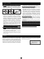
Important Safety Instructions
SAVE THESE INSTRUCTIONS
The manual contains instructions and warnings that should be followed during the installation, operation and storage of this product. Failure
to heed these warnings will void your warranty.
UPS Location Warnings
• The UPS is designed for indoor use only in a controlled
environment, away from excess moisture, temperature extremes,
conductive contaminants, dust or direct sunlight.
• Leave adequate space around all sides of the UPS for proper
ventilation.
• Do not mount unit with its front or rear panel facing down (at
any angle). Mounting in this manner will seriously inhibit the
unit's internal cooling, eventually causing product damage not
covered under warranty.
UPS Connection Warnings
• Connect the UPS directly to a properly grounded AC power outlet.
Do not plug the UPS into itself; this will damage the UPS.
• Do not modify the plug of the UPS, and do not use an adapter that
eliminates the ground connection of the UPS.
• Do not use extension cords to connect the UPS to an AC outlet.
The warranty will be void if anything other than Tripp Lite surge
suppressors are used to connect the UPS to an outlet.
• If the UPS receives power from a motor-driven AC generator, the
generator must provide clean, filtered, computer-grade output.
Equipment Connection Warnings
• Do not use Tripp Lite UPS Systems for life support applications in
which a malfunction or failure of a Tripp Lite UPS System could cause
failure or significantly alter the performance of a life support device.
• Do not connect surge suppressors or extension cords to the output
of the UPS. This might damage the UPS and will void the surge
suppressor and UPS warranties.
Battery Warnings
• The UPS does not require routine maintenance. Do not open the
UPS for any reason. There are no user-serviceable parts inside.
• Batteries can present a risk of electrical shock and burns from high
short-circuit current. Observe proper precautions. Do not dispose
of the batteries in a fire. Do not open the UPS or batteries. Do not
short or bridge the battery terminals with any object. Unplug and
turn off the UPS before performing battery replacement. Use tools
with insulated handles. Battery replacement should be performed
only by authorized service personnel using the same number and
type of batteries (sealed Lead-Acid). The batteries are recyclable.
Refer to your local codes for disposal requirements. Tripp Lite
offers a complete line of replacement batteries at
www.tripplite.com.
• Do not attempt to add external batteries to the UPS.

2
CAUTION: The UPS must be plugged into a live AC outlet and
turned on for 24 hours after initial installation to fully charge the
internal battery. Connected equipment will receive utility-
supplied AC power (if present) immediately after the UPS is
plugged in and turned on, but connected equipment will not
receive full battery backup in the event of a blackout or severe
brownout unless the internal battery is fully charged.
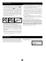
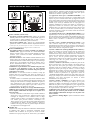
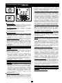
STEP 1: Place the UPS in a horizontal or vertical (tower) position.
To install the UPS in a 4-post rack, attach the included hardware to the
UPS as shown in diagram . To install the UPS in a 2-post rack,
attach the included hardware to the UPS as shown in diagram .
Then, using an assistant if necessary, lift the UPS and attach it to a
standard rack with user-supplied hardware. The UPS will stand in a
tower position without the aid of the included hardware. For increased
stability, however, Tripp Lite recommends attaching the included
hardware as shown in diagram . In either position, the user must
determine the fitness of hardware and procedures before installation.
The UPS and included hardware are designed for common rack types
and may not be appropriate for all applications. The LCD display may
be rotated to match the orientation of the UPS. Carefully insert a small
tool in the slots at the side of the LCD to remove it from the UPS
housing, then rotate the LCD and press it back into place.
CAUTION: To balance the UPS safely when placed in a vertical
position, make sure the LCD Display is located at the top of the
front panel.
STEP 2: Connect a user-supplied power cord* to the UPS, then
plug the UPS into a wall outlet.**
After plugging the UPS into a wall outlet, push the ON/OFF button
for one second to turn the UPS on (see Basic Operation section).
Please Note! The UPS will not turn on automatically in the
presence of live utility power.
*The UPS system does not include an input power cord. The user-supplied power cord
should have an IEC-320-C13 connector (commonly found on detachable power cords
for desktop computers) at one end in order to connect to the AC input of the UPS.
**Use an outlet that doesn't share a circuit with a heavy electrical load such as an air
conditioner or refrigerator.
STEP 3: Plug your equipment into the UPS.
Insert the female connectors of the detachable power cords that
came with the UPS system into the AC inputs of the attached
equipment. Insert the male connectors into any of the UPS system's
available outlets.
The UPS is designed to support electronic equipment only.
Connected equipment will overload the UPS if the total VA ratings
for all the equipment connected to the outlets exceeds the UPS
Output Capacity. To find VA ratings, look at equipment nameplates.
If the equipment is listed in amps, multiply the number of amps by
230 volts to determine VA. (Example: 1 amp × 230 volts = 230 VA).
If unsure whether the outlets are overloaded, run a self-test (see
“MUTE/TEST” Button description).
STEP 4: Optional Installation. The UPS includes USB and RS-232
communication ports as well as Tel/DSL/Ethernet and Coaxial
surge protection jacks. These connections are optional; the UPS
will work properly without these connections.
Not compatible with PoE (Power over Ethernet) applications.
C
B
A
A
C
B
Quick Installation
Storage
To avoid battery drain, all connected equipment should be turned off
and disconnected from the UPS. Press and hold the ON/OFF button
for one second. Your UPS will be completely turned off (deactivated),
and will be ready for storage. If you plan on storing your UPS for an
extended period, fully recharge the UPS batteries every three months.
Plug the UPS into a live AC outlet, turn it on by pressing and holding
the ON/OFF button for one second, and allow the batteries to
recharge for 24 hours. If you leave your UPS batteries discharged for
a long period of time, they will suffer a permanent loss of capacity.
Note on Labeling
Two symbols are used on the label.
V~ : AC Voltage
V : DC Voltage

3
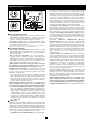
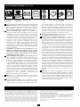
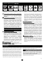
Basic Operation
(Front Panel)
“ON/OFF” Button
• To Turn the UPS On: Press and hold the ON/OFF Button for one
second.* If utility power is absent, pressing the Button will “cold-
start” the UPS, i.e. turn it on and supply power from battery.**
• To Turn the UPS Off: Press and hold the ON/OFF Button for one
second.* The UPS will be turned off completely.
* The alarm will beep once after one second has passed. ** Providing runtime
proportionate to the UPS battery's level of charge.
“MUTE/TEST” Button
• To Silence (or “Mute”) UPS Alarms: Briefly press and release
the MUTE/TEST button. Note: continuous alarms that warn
to shut down connected equipment immediately cannot be
silenced.
• To Run a Self-Test: with the UPS plugged in and turned on,
press and hold the MUTE/TEST button for two seconds.
Continue holding the button until the alarm beeps several times
and the UPS performs a self-test. See “Results of a Self-Test”
below. Note: connected equipment may remain connected during
a self-test.
CAUTION! Do not unplug the UPS to test the battery. This will
remove safe electrical grounding and may introduce a
damaging surge into network connections.
Results of a Self-Test: The test will last approximately 10 seconds
as the UPS switches to battery to test load capacity and charge. All
LCD Display icons will be illuminated and the UPS alarm will
sound.
•If the “FAULT” icon remains lit and the alarm continues to
sound after the test, the battery-supported outlets are overloaded.
To clear the overload, unplug some equipment from the
battery-supported outlets and run the self-test repeatedly until
the “FAULT” icon is no longer lit and the alarm is no longer
sounding.
CAUTION! Any overload that is not corrected by the user
immediately following a self-test may cause the UPS to shut
down and cease supplying output power in the event of a
blackout or brownout.
• If the “REPLACE” icon remains lit and the alarm continues to
sound after the test, the UPS batteries need to be recharged
or replaced. Allow the UPS to recharge continuously for 24
hours, and repeat the self-test. If the icon continues to
illuminate after repeated self tests, contact Tripp Lite for service.
Battery replacement should only be performed by
qualified service personnel. If the UPS requires battery
replacement, Tripp Lite offers a complete line of replacement
batteries at www.tripplite.com.
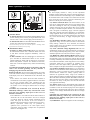
LCD Display
The LCD Display indicates a variety of UPS operational
conditions. All descriptions apply when the UPS is plugged into an
AC outlet and turned on. The LCD display may be rotated to match
the orientation of the UPS. Carefully insert a small tool in the slots
at the side of the LCD to remove it from the UPS housing, then
rotate the LCD and press it back into place.
3-1) “INPUT VOLTAGE” Meter: This meter measures, in real
time, the AC voltage that the UPS system receives from the utility
wall outlet. Although the meter may occasionally display input
voltages which stray (due to poor quality utility service) outside
the range of standard computer tolerance, rest assured that the
UPS is designed to continuously supply connected equipment
with stable, computer-grade output through the use of automatic
voltage regulation. In the event of a blackout (power loss), severe
brownout (low power) or overvoltage (high power), the UPS will
rely on the internal battery to supply computer-grade output
voltage.
3-2) “BATTERY CAPACITY” Meter: This meter displays the
approximate charge level (in 20% increments) of the internal
battery. During a blackout or severe brownout, the UPS will
switch to battery power, the “ON BAT” icon will be illuminated
and the charge level will deplete.
3-3) “AVR” (Automatic Voltage Regulation) Icon: This icon
will illuminate whenever the UPS is automatically correcting low
AC line voltage without depleting battery power. This is a normal,
automatic operation of the UPS, and no action is required.
3-4) “REPLACE” (Battery Recharge/Replace) Icon: This icon
will illuminate and an alarm will sound after a self-test to indicate
the UPS battery needs to be recharged or replaced. Allow the UPS
to recharge continuously for 24 hours, and repeat the self-test. If the
icon continues to illuminate, contact Tripp Lite for service. Battery
replacement should only be performed by qualified service
personnel. If the UPS requires battery replacement, Tripp Lite
offers a complete line of replacement batteries at www.tripplite.com.
3-5) “ON BAT” (On Battery) Icon: During a severe brownout or
blackout, this icon illuminates and an alarm sounds (4 short beeps
followed by a pause) to indicate the UPS is operating from its
internal batteries. Monitor the “Battery Capacity” Meter to
determine the approximate battery charge level available to
support equipment. During a prolonged brownout or blackout, the
alarm will sound continuously (and the “BATTERY CAPACITY”
Meter will show one 20% capacity segment shaded) to indicate
the batteries are nearly out of power; save files and shut down
your equipment immediately.
3-6) “FAULT” Icon: This icon will illuminate and an alarm will
sound after a self-test to indicate the battery-supported outlets are
overloaded. To clear the overload, unplug some of the equipment
from the battery-supported outlets and run the self-test repeatedly
until the icon is no longer illuminated and the alarm is no longer
sounding.
CAUTION! Any overload that is not corrected by the user
immediately following a self-test may cause the UPS to shut
down and cease supplying output power in the event of a
blackout or brownout.
3-7) LCD Dimmer: Adjusts the brightness of the LCD Display.
ON/OFF Button
MUTE/TEST Button
1
2
LCD Display
3
3-1
3-2
3-3
3-4
3-5
3-6
1
2
3
3-7

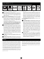
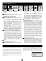
Battery Backup/Surge Protected Outlets: These IEC-320-C13
outlets provide both battery backup and surge protection. Plug
your computer, monitor and other critical equipment into these
outlets. NOTE: DO NOT PLUG LASER PRINTERS INTO
THESE OUTLETS.
USB or Serial Communication Port: These ports can connect
your UPS to a computer for automatic file saves and unattended
shutdown in the event of a power failure. Use with Tripp Lite’s
PowerAlert Software and appropriate USB or DB9 serial cable.
PowerAlert Software is available for download FREE at
www.tripplite.com. Note: This connection is optional. The UPS
will work properly without this connection.
CAUTION: Users should take care to minimize electro-static
events. In the event of a severe electro-static discharge on or
near the USB port, this UPS may shut down automatically. In
the case of a shutdown, the UPS must be turned back on.
Tel/DSL/Ethernet Protection Jacks: RJ-45 jacks provide surge
protection for a single telephone, fax, modem, DSL or Ethernet
line. Connect a telephone cord or Ethernet cable from the wall
jack or original data source jack directly to the Tel/DSL/Ethernet
jack labeled “IN.” Connect a telephone cord or Ethernet cable
from the Tel/DSL/Ethernet jack labeled “OUT” directly to the
equipment to be protected. The UPS system must be the first item
connected to the wall jack or original data source jack. The UPS
system must be plugged into a grounded AC outlet in order to
provide surge protection to connected equipment. Connecting
your equipment to these jacks is optional. Your UPS will work
properly without this connection.
AC Input: This IEC-320-C14 connector accepts a user-
supplied power cord with a plug appropriate for the local site's
utility outlets.
Coaxial Protection Jacks: Gold-plated jacks provide surge
protection for a single coaxial line. Connect a coaxial cable from
the wall jack directly to the coaxial jack labeled “IN.” Connect a
coaxial cable from the coaxial jack labeled “OUT” directly to the
equipment to be protected. The UPS system must always be the
first item connected to the wall jack. The UPS system must be
plugged into a grounded AC outlet in order to provide surge
protection to connected equipment. Make sure coaxial cables
connected to satellite dishes, antennas, etc. are also grounded.
Connecting your equipment to these jacks is optional. The UPS
will work properly without this connection.
Mounting Hardware: Adapts the UPS to either tower or 2U rack
installation.
Power Sensitivity Dial: The default setting for the dial is full
counterclockwise rotation. The default allows the UPS to protect
against waveform distortions in the AC input power by switching
to battery power for as long as the problem is detected. At sites
supplied by substandard utility power or generator power, chronic
waveform distortion (or frequent brownouts) could cause the UPS
to switch to battery too often, draining battery reserves. It may be
possible to optimize the level of protection for a particular site by
experimenting with sensitivity settings. As the dial is turned
clockwise, the UPS becomes more tolerant of waveform
variations. WARNING: Equipment may malfunction when
exposed to distorted AC waveforms. When experimenting with
sensitivity settings, operate connected equipment in a safe “test
mode” in order to evaluate results without disrupting critical
operations. Continue the test until all expected line conditions
have been encountered.
Circuit Breaker: If the current drawn by the equipment
connected to the UPS exceeds the Maximum Load Rating for
longer than a few seconds, the circuit breaker will activate and
interrupt AC power to prevent possible damage. When the circuit
breaker activates, its plunger will pop up. Disconnect excess
equipment and allow the breaker to cool one minute before
depressing the plunger to reset the breaker.
4
Basic Operation
(Rear Panel)
Tel/DSL/Ethernet
Protection Jacks
USB Port/RS-232
Serial Port (DB9)
AC InputBattery Backup/Surge
Protected Outlets
Before returning your UPS for service, follow these steps: 1. Review the installation and
operation instructions in this manual to ensure that the service problem does not originate from
a misreading of the instructions. 2. If the problem continues, do not contact or return the UPS to
the dealer. Instead, call Tripp Lite at (773) 869-1234 domestically or (773) 869-1212
internationally. A service technician will ask for the UPS model number, serial number and
purchase date and will attempt to correct the problem over the phone. 3. If the problem requires
service, the technician will issue you a Returned Material Authorization (RMA) number, which is
required for service. If you require packaging, the technician can arrange to send you proper
packaging. Securely pack the UPS to avoid damage during shipping. Do not use Styrofoam
beads for packaging. Any damages (direct, indirect, special, incidental or consequential) to the
UPS incurred during shipment to Tripp Lite or an authorized Tripp Lite service center is not
covered under warranty. UPS Systems shipped to Tripp Lite or an authorized Tripp Lite service
center must have transportation charges prepaid. Mark the RMA number on the outside of the
package. If the UPS System is within the 2-year warranty period, enclose a copy of your sales
receipt. Return the UPS for service using an insured carrier to the address given to you by the
Tripp Lite service technician.
Regulatory Compliance Identification Numbers
For the purpose of regulatory compliance certifications and identification, your Tripp Lite
product has been assigned a unique series number. The series number can be found on the
product nameplate label, along with all required approval markings and information. When
requesting compliance information for this product, always refer to the series number. The
series number should not be confused with the marking name or model number of the product.
Tripp Lite follows a policy of continuous improvement. Product specifications are subject to
change without notice.
9
10
8
7
4
5
6
4 5 6 7
Coaxial
Protection Jacks
8 9
Mounting Hardware
Power Sensitivity
Dial
10
11
Circuit Breaker
11
Service
Page is loading ...
Page is loading ...
Page is loading ...
Page is loading ...
Page is loading ...
Page is loading ...
Page is loading ...
Page is loading ...
Page is loading ...
Page is loading ...
Page is loading ...
Page is loading ...
-
 1
1
-
 2
2
-
 3
3
-
 4
4
-
 5
5
-
 6
6
-
 7
7
-
 8
8
-
 9
9
-
 10
10
-
 11
11
-
 12
12
-
 13
13
-
 14
14
-
 15
15
-
 16
16


Tripp Lite SMX1500LCD User manual
- Type
- User manual
Ask a question and I''ll find the answer in the document
Finding information in a document is now easier with AI
in other languages
- français: Tripp Lite SMX1500LCD Manuel utilisateur
- español: Tripp Lite SMX1500LCD Manual de usuario
Related papers
-
Tripp Lite HTRL15UPS User manual
-
-
-
-
-
-
Tripp Lite SMX1000LCD User manual
-
-
-
Other documents
-
Dell Vostro 200 Quick start guide
-
Dell Vostro 400 Quick start guide
-
-
Roland FR-3x Owner's manual
-
-
-
-
-
-