Bosch HES7282U/01 Installation guide
- Category
- Tumble dryers
- Type
- Installation guide
Page is loading ...

Table of Contents
Important Safety Instructions ................................... 1
Installation ................................................. 2
Before You Begin ...................................................... 2
Tools and Parts Needed ........................................................ 2
Additional Parts Needed for Hard Wire Installations ................................... 2
Parts Included ................................................................ 2
Cabinet Requirements .......................................................... 2
Electrical Requirements ......................................................... 4
Installation ............................................................ 5
Installation Tips ............................................................... 5
Install Ventilation .............................................................. 5
Prepare Walls and Floor ........................................................ 5
Prepare Range ............................................................... 5
Install Strain Relief ............................................................. 5
Connect Electric .............................................................. 6
Attach Anti-Tip Bracket to Floor .................................................. 12
Complete the Installation ....................................................... 13
Service .............................................................. 14
Data Tag .................................................................... 14
Questions?
1-800-944-2904
www.boschappliances.com
5551 McFadden Ave.
Huntington Beach, CA 92649
We look forward to hearing from you!

Important Safety Instructions
READ AND SAVE THESE INSTRUCTIONS
Important Safety
Instructions
WARNING: If the information in this manual is not followed exactly, a fire or
explosion may result causing property damage, personal injury or death.
• Ask your dealer to recommend a qualified technician and an authorized repair
service.
• Install only per installation instructions provided in the literature package for
this range.
• Important - Save for local electrical inspector's use.
Safety Codes and Specifications
• Be sure your appliance is properly installed and grounded by a qualified tech-
nician in accordance with the National Electrical Code ANSI/NFPA No. 7 lat-
est edition and local electrical code requirements.
• Local codes vary. Installation, electrical connections and grounding must
comply with all applicable codes.
• This appliance has been tested in accordance with ANSI/UL 858 Standard for
Safety for Household Ranges and CAN/CSA-22.2 No. 61 National Standard
of Canada for Household Cooking Ranges. It is the responsibility of the owner
and the installer to determine if additional requirements and standards apply
in specific installations.
Equipment and Usage Safety Requirements
• Unit is heavy and requires at least two persons or proper equipment to move.
• Stepping, leaning or sitting on the doors or drawers of this range can result in
serious injuries and also cause damage to the range.
• Do not allow children to climb or play around the range. The weight of a child
on an open door may cause the range to tip, resulting in serious burns or
other injury.
• Do not store items of interest to children in the cabinets above a range or on
the backguard of a range. Children climbing on the range to reach items could
be seriously injured.
• To eliminate the risk of burns or fire by reaching over heated surface units,
cabinet storage space located above the surface units should be avoided. If
cabinet storage is provided, the risk can be reduced by installing a range hood
that projects a minimum of five inches (12.7 cm) beyond the bottom of the
cabinets.
• Remove all tape and packaging before using the range. Destroy the packag-
ing after unpacking the range. Never allow children to play with packaging
material.
• Do not repair or replace any part of the appliance unless specifically recom-
mended in the manuals. All other servicing should be done by a qualified
technician. This may reduce the risk of personal injury and damage to the
range.
• Never modify or alter the construction of a range by removing leveling legs,
panels, wire covers, anti-tip brackets/screws, or any other part of the product.
• DO NOT LIFT RANGE BY DOOR HANDLE.
• Remove the door for easier handling and installation. See 'Removing Oven
Door' in the Maintenance section of the Use and Care Manual.
• Do not use the warming drawer (if equipped) or oven for storage.
• Hidden surfaces may have sharp edges. Use caution when reaching behind
or under range.
English 1

Power Requirements and Electrical Grounding Instructions
• Before installing, turn power OFF at the service panel. Lock service panel to
prevent power from being turned ON accidentally.
• Know how to disconnect the power to the range at the circuit breaker or fuse
box in case of an emergency.Installation
Installation
Before You Begin
Tools and Parts Needed
Additional Parts Needed For
Hard Wire Installations
Parts Included
Cabinet Requirements
• 50 Amp Power Supply Cord Kit (not necessary for Canadian installations)
• Measuring Tape
• Phillips Head Screwdriver
• 1-1/4" (31.8 mm) Wrench
• Pencil
• T-20 Torx Screwdriver
• Screws (2) and Anchors (2) for Anti-Tip Bracket (Style will vary depending on
mounting surface)
• Level
• Drill and Drill Bit
• Safety Gloves and Goggles
• Tape (Optional)
• Cloth or Cardboard (Optional - to Protect Floor)
• Flexible Conduit (For Hard Wire Installation Only)
• Torque Wrench (For Hard Wire Installation Only)
• Note: Power Supply Cord Kit Not Necessary For Hard Wire Installations
• Anti-Tip Bracket
• Terminal Lugs (For Use With Hard Wire Installations) (not necessary for
Canadian installations)
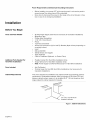
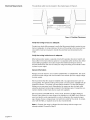
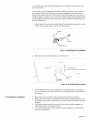
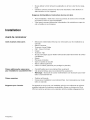
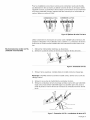
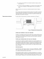
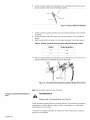
This unit is designed for installation near adjacent walls and projecting surfaces
constructed of combustible materials. Allow a minimum of 30 inches (76.2 cm)
between cabinets where range is to be installed (0.47" (12 mm) clearance from
range sidewall to cabinet required in Canada).
_/_0e'i(7e6e'2 Ca_)inMei_imum
Figure 1: Cabinet Clearances
English 2

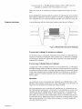
RequiredClearances:
TheseclearanceinstructionsweredeterminedusingStandardAmericancabinets.
Standardbasecabinetsmeasure36"(91.4cm)highx24"(60.9cm)deep.Cabi-
netsoverthecookingsurfaceandcabinetsadjacenttothoseoverthecooking
surfacemeasure13inches(33cm)deepfrombackwall.Ifnonstandardcabinets
areused,careshouldbetakentoalterdimensionsaccordingly.
NOTE:SomecabinetfinishescannotsurvivethetemperaturesallowedbyU.L.for
appliances,particularlyself-cleaningovens;thecabinetsmaydiscolororstain.
Thisismostnoticeablewithlaminatedcabinets.
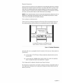
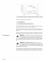
Fromcooktoptomaterialsabove:
Theremustbeaminimumclearanceof30inches(76.2cm)betweenthetopof
th c°°k!n SUdace and th botto Of an u protected w0od o meta cab net-............................................
30in (76.2cm)
• min. centered Q
4in (10.2 cm) 30in(76.2 cm) min. 4in (10.2 cm)
min ]1 _ JL_" min >
J
no clearance required (12 mm clearance from
range sidewall to cabinet required in Canada.)
Figure 2: Cooktop Clearances
24 inches (61 cm) is acceptable when the bottom of the wood or metal cabinet is
protected by
(a) not less than 1/4" (6.35 mm) of flame retardant material which must be
covered with
(b) not less than No. 28 MSG sheet metal, 0.015 inch (.381 mm) stainless
steel' or 0.024 inch (.601 mm) aluminum or copper.
From range walls to adjacent materials (see Figure 2 above):
No clearance is required from unit walls to adjacent vertical combustible walls on
rear, right or left. Clearance from range top to adjacent vertical walls must be at
least 4" (10.2 cm).
English 3

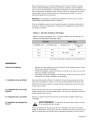
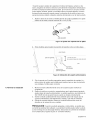
Electrical Requirements The electrical outlet must be located in the shaded space in Figure 3.
21" (533.4 mm)
30"
(762 mm)
Figure 3: Cooktop Clearances
Verify that wiring to house is adequate.
Contact your local utility company to verify that the present electric service to your
home is adequate. In some instances, the size of the wiring to the house and ser-
vice switch must be increased to handle the electrical load demanded by the
range.
Verify that wiring inside house is adequate.
Most wiring codes require a separate circuit with separate disconnect switch and
fuses either in the main entrance panel or in a separate switch and fuse box. Most
local building regulations and codes require that electrical wiring be done by
licensed electricians. Be sure to install your range according to the electric codes
in place in your region.
General Information
Ranges are dual rated for use on either 120/240 VAC or 120/208 VAC. See chart
at right for power ratings and circuit breaker sizes based upon the supply voltage
for each model.
We recommend that the range be installed with a UL approved power cord set
(not supplied). The electrical rating of the power cord set must be 120/240 volt, 50
amperes minimum. The power cord set shall be marked "For Use with Ranges."
Always use a new power cord. Alternatively, the range can also be hard wired
using the aluminum terminal lugs included in the literature pack. If using this con-
nection, flexible conduit must also be used (not supplied).
We recommend a 50 AMP, 60 Hz, 4 wire circuit; However, the NEC (National
Electric Code) allows for some ranges to be installed on a 40 AMP circuit. Refer to
your local electric code requirements in order to determine the required amper-
age. Always choose a range power cord set that is rated for the circuit. In compli-
ance with the NEC, a separate circuit is also recommended.
Note: In Canada, the range is shipped from the factory with the range cord
already installed. Proceed to Step 9.
English 4

ForinstallationsotherthanthoseinCanada,installthestrainreliefandconnect
therangecord(orwireconductors)asdescribedinthefollowingsteps.
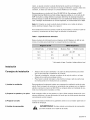
Table 1: Electrical Specifications
Check data plate for kW rating. Reference kW rating in table to determine amper-
age requirements.
Installation
Installation Tips
1) Install Ventilation
2) Prepare Walls and Floor
3) Prepare Range
4) Install Strain Relief
At 120/240 Vo ts At 120/208 Vo ts US Modes Canadian Modets:
12.3 9.2 40 or 50*
50
13.5 10.2 50
* Varies by location. Refer to local electric code.
• Tape warming drawer or storage drawer shut to keep it from opening while
installing the range.
• During installation, place a portion of the box or a piece of cloth under the
range to protect floors.
• To make range lighter and easier to handle, remove door (see instructions in
Use and Care manual).
We strongly recommend the installation of a ventilation hood above this range.
For most kitchens a certified hood rating of not less than 300 CFM is recom-
mended. The range hood must be installed according to instructions furnished
with the hood.
Seal any holes in the walls or floor. Remove any obstructions (extra electrical or
gas connections, etc.) so that range will rest against wall properly.
Place range in front of cabinets where it is to be installed. Remove any packaging.
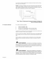
,_ WARNING: The strain relief provided with your range cord must be
properly installed.
Place strain relief in knockout below terminal block (See Figure 4). Feed range
cord through hole and strain relief up to terminal block. Allow for slack in the cord
between the strain relief and terminal block. Once cord length/slack has been
adjusted, attach strain relief per instructions included with strain relief.
Tip: The knockout panel (below the terminal block) can be removed from the
range to install the strain relief: Remove panel from range, install strain relief in
panel and reattach. DO NOT remove entire range back panel.
English 5

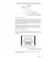
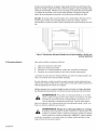
Electrical connection
(found behind terminal block cover)
t
Feed range cord through strain /
relief in knockout panel here.
Figure4: Electrical Connection and Strain Releif Knockout Panel Locations
5) Connect Electric
There are four possible electrical connections:
1. Four wire range cord
2. Three wire range cord
3. Four wire flexible conduit connection (hard wire)
4. Three wire flexible conduit connection (hard wire)
The four wire range cord connection is the recommended method, but where local
codes permit, three wire connections are also acceptable.
As an alternative to the range cord, the appliance can also be hard wired with
either a three or four wire connection. In this case, the terminal lugs supplied must
be used.
Always verify that your chosen connection complies with all applicable codes. See
"Electrical Specifications" at the beginning of this manual for further information.
WARNING: To prevent electrical shock, the grounding prong on the
range cord should not be cut or removed under any circumstances. It
must be plugged into a matching grounding type receptacle and con-
nected to a correctly polarized 240- Volt circuit. If there is any doubt as to whether
the wall receptacle is properly grounded, have it checked by a qualified electri-
cian.
WARNING: Risk of Electric Shock or Fire. Frame grounded to
neutral through a ground strap. Grounding through the neutral conduc-
tor is prohibited for new branch-circuit installations (1996 NEC), mobile
homes, and recreational vehicles, or in an area where local codes prohibit ground-
ing through the neutral conductor.
For installations where grounding through the neutral conductor is prohibited, (a)
disconnect the link from the neutral, (b) use grounding terminal or lead to ground
unit, (c) connect neutral terminal to lead branch circuit neutral in usual manner
English 6

(whentheapplianceistobeconnectedbymeansofacordkit,use4-conductor
cordforthispurpose)
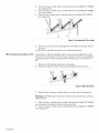
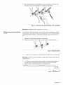
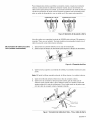
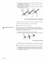
3=WIRE HOOK UP 4=WIRE HOOK UP
Figure 5: Grounding Options
5A) Four Wire Range Cord Connec-
tion (Recommended Method)
Use only cord kits rated 125/250 volts (minimum), 50 amperes and labeled "For
Use with Ranges". Strain relief provided with cord must be installed per instruc-
tions included with cord.
1. Disconnect electrical power at breaker box.
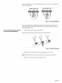
Remove the terminal block cover to expose the terminal block
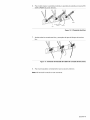
Figure 6:4 Wire Connection
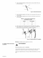
2. Remove top nut, star washer, and round washer from each post.
Note: DO NOT remove last round washer, last nut or internal wiring leads.
3. Remove screw from bottom end of ground strap.
English 7

4. Removegroundstrapfromcenterpost,rotatesothatwideendisattopand
attachwideendtorangethroughholebelowjunctionbox.Attachgreenwire
......................................o top gr0undstrap. ghte Screw:..........................................................................................................................................................................................................................................................................................................................................................................
/
green ground screw
ground strap
ground wire
Figure7: Four Wire Range cord Connection - Ground Strap and Wire
5. Attach red wire, round washer, star washer and nut IN THIS ORDER to left
post.
6. Attach white wire, round washer, star washer and nut IN THIS ORDER to cen-
ter post.
7. Attach black wire, round washer, star washer and nut IN THIS ORDER to right
......................................Post-...................................................................................................................................................................................................................................................................................................................................................................................................
red
white
black
Figure8: Four Wire Range Cord connection Continued
5B) Three Wire Range Cord Connec-
tion
8. Tighten all connections securely and replace terminal block cover.
9. Properly secure strain relief (see previous section).
Note: DO NOT plug in range at this time.
The Four Wire Connection (above) is preferred, but where local codes and ordi-
nances permit grounding through neutral and where conversion to four wire is
impractical, the unit may be connected to the power supply via a three wire con-
nection.
1. Disconnect electrical power at breaker box.
English 8

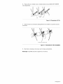
2. Removetheterm!nalblock€ovetoexp0setheterm!naib!ock...........................................................................................................................................
Figure9: Terminal Block
3. Remove top nut, star washer, and round washer from each post.
Note: DO NOT remove last round washer, last nut or internal wiring leads.
4. Attach white wire, round washer, star washer and nut IN THIS ORDER on top
of ground strap on center post.
5. Attach red wire, round washer, star washer and nut IN THIS ORDER to left
post.
6. Attach black wire, round washer, star washer and nut IN THIS ORDER to right
post.
/
ground strap
red
white
black
Figure 10: Three Wire Connection
7. Tighten all connections securely and replace terminal block cover.
/
green ground screw
Figure 11: Completed Three Wire Range Cord Connection
8. Properly secure strain relief (see previous section).
English 9

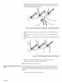
5C) Four Wire Flexible Conduit Con-
nection
Note: DO NOT plug in range at this time.
1. Disconnect electrical power at the breaker box.
2. Remove the terminal block cover to expose the terminal block.
3. Remove the top nut, star washer, and round washer from each post.
Note: DO NOT remove last round washer, last nut or internal wire leads.
4. Remove screw from bottom end of ground strap.
5. Remove ground strap from center post. Discard.
6. Attach one terminal lug (packaged with this manual) through hole below termi-
nal block with ground screw.
7. Place one terminal lug (packaged with this manual) on each post. Replace the
star washer and round washer and secure with 20 inch pounds of torque.
8. Strip 3/8 (9.53 mm) inches of insulation from the end of the wire.
3/8 "
Figure 12: Wire Stripping
9. Insert the insulated grounding wire into the lug below the terminal block.
10. Insert stripped end of white wire into the center lug. Secure the clamping-
screw.
..J'j
lug . __2'
wire
clamping screw
Figure 13: Attaching Wire to Lug
11. Insert stripped end of red wire into the left lug. Secure clamping screw.
12. Insert black wire into the right lug. Secure clamping screw.
13. Tighten each clamping screw with the appropriate torque (see table).
Table 2: Appropriate Torque Levels for Aluminum or Copper Wire
6 35 3.95
English 10

14.Properlysecureflexibleconduitatknockoutonangleandatsupplysidejunc-
tionbox.Thewiringisnowcomplete.
\
black wire
red wire
white wire
green ground wire
Figure 14: Completed Four Wire Flexible Conduit Connection
Note: DO NOT plug in range at this time.
5D) Three Wire Flexible Conduit Con- The Four Wire Connection is preferred, but where local codes and ordinances
nection permit grounding through neutral and/or conversion to four wire is impractical, unit
may be connected to the power supply via a three wire connection.
1. Disconnect electrical power at the breaker box.
2: Remov theterm! a bloc cove t expos !h !er ! boc ............................................................................................................................................
Figure 15: Terminal Block
3. Remove the top nut, star washer, and round washer from each post.
Note: DO NOT remove last round washer, last nut or internal wire leads.
4. Place one terminal lug (packaged with this manual) on each post. Replace the
star washer and round washer and secure with 20 inch pounds of torque.
5. Strip 3/8 (9.53 mm) inches of insulation from the end of each wire.
3/8 "
Figure 16: Wire Stripping
English 11

6. Insertstrippedendofwhitewireintothecenterlugontopofthegroundstrap.
Securetheclampingscrew.
lug
wire
clamping screw
Figure 17: Attaching Wire to Lug
7. Insert stripped end of red wire into the left lug. Secure clamping screw.
8. Insert stripped end of black wire into the right lug. Secure clamping screw.
9. Tighten each clamping screw with the appropriate torque (See table below).
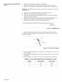
Table 3: Appropriate Torque Levels for Aluminum or Copper Wire
6
10. Properly secure flexible conduit at knockout panel on range and at supply
side junction box. The wiring is now comple!e: :......................................................................................................................................................................................................................................................................................
green g'ound screw
Figure 18: Completed Three Wire Flexible Conduit Connectiog
6) Attach anti-tip bracket to floor
Note: DO NOT plug in range at this time.
WARNING
RANGE TIPPING HAZARD
All ranges can tip and injury could result. To prevent accidental tipping of the
range, attach it to the wall, floor or cabinet by installing the Anti-Tip Device sup-
plied.
English 12

•Ariskoftip-overmayexistiftheapplianceisnotinstalledinaccordancewith
theseinstructions.
• Iftherangeispulledawayfromthewallforcleaning,service,oranyotherrea-
son,ensurethattheAnti-TipDeviceisproperlyreengagedwhentherangeis
pushedbackagainstthewall.Intheeventofabnormalusage(suchasaperson
standing,sitting,orleaningonanopendoor),failuretotakethisprecautioncould
resultintippingoftherange.Personalinjurymightresultfromspilledhotliquidsor
fromtherangeitself.
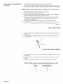
1. Adjustheightofrangeandlevelbyrotatingtheadjustablelegsupportsonthe
bottomoftherange,using1-1/4"(31.75mm)wrench.
drawer
adjustableleg
Figure 19: Adjusting the Leg Support
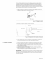
2. Measure to locate bracket position as shown below.
rearwall
cabinet wall
1 9/16" (39.7 mm)
from rear wall to center of screw hole
floor
anti-tippin g
device
flush against
cabinetwall
Figure20: Anti-tip Bracket Location
7) Complete the installation
3. Secure bracket with 2 screws adequate for mounting surface, not included.
(i.e.; for wood floor use wood screws for concrete floor use concrete anchors
and screws).
1. Move range close enough to the opening to plug into the receptacle.
2. Slide range into position ensuring that the left back leg slides under the anti-
tip bracket. Range will sit 314" (19.05 mm) away from back wall when properly
installed.
3. Carefully tip range forward to ensure that the anti tip bracket engages the
range back brace and prevents tip-over.
4. Turn on electrical power. Check range for proper operation as described in
Use and Care Manual.
English 13

CAUTION: If the display flashes and beeps, the polarity of the wiring may be
reversed. Reversed polarity can damage the range and can result in electrical
shock hazard. Immediately switch off power at the breaker and return to Step 5-
Connect Electric.
Service
Data Tag
To reach a service representative, see the contact information at the front of the
manual. Please be prepared to provide the information from the data tag on the
appliance.
The data tag is on the appliance frame near the drawer. Open the drawer to view
it.
English 14
Page is loading ...
Page is loading ...
Page is loading ...
Page is loading ...
Page is loading ...
Page is loading ...
Page is loading ...
Page is loading ...
Page is loading ...
Page is loading ...
Page is loading ...
Page is loading ...
Page is loading ...
Page is loading ...
Page is loading ...
Page is loading ...
Page is loading ...
Page is loading ...
Page is loading ...
Page is loading ...
Page is loading ...
Page is loading ...
Page is loading ...
Page is loading ...
Page is loading ...
Page is loading ...
Page is loading ...
Page is loading ...
Page is loading ...

Servicio
Etiqueta de informacion
Consulte la informaci6n de contacto al inicio del manual para contactar a un rep-
resentante de servicio. Por favor, tenga a la mano la informaci6n que se encuen-
tra en la etiqueta de informaci6n del producto.
La etiqueta de informaci6n se encuentra en el bastidor del aparato cerca del
caj6n. Abra el caj6n para verla.
YOUR LIFE. OUR INSPIRATION.
5551 McFadden Avenue, Huntington Beach, CA 92649 • 800-944-2904 • www.boschappliances.com
9000087166 (No ECO) • 10052 Rev I • 03!06 • © BSH Home Appliances Corporation 2005 • Litho U. S. A.
-
 1
1
-
 2
2
-
 3
3
-
 4
4
-
 5
5
-
 6
6
-
 7
7
-
 8
8
-
 9
9
-
 10
10
-
 11
11
-
 12
12
-
 13
13
-
 14
14
-
 15
15
-
 16
16
-
 17
17
-
 18
18
-
 19
19
-
 20
20
-
 21
21
-
 22
22
-
 23
23
-
 24
24
-
 25
25
-
 26
26
-
 27
27
-
 28
28
-
 29
29
-
 30
30
-
 31
31
-
 32
32
-
 33
33
-
 34
34
-
 35
35
-
 36
36
-
 37
37
-
 38
38
-
 39
39
-
 40
40
-
 41
41
-
 42
42
-
 43
43
-
 44
44
-
 45
45
-
 46
46


Bosch HES7282U/01 Installation guide
- Category
- Tumble dryers
- Type
- Installation guide
Ask a question and I''ll find the answer in the document
Finding information in a document is now easier with AI
in other languages
- français: Bosch HES7282U/01 Guide d'installation
- español: Bosch HES7282U/01 Guía de instalación
Related papers
-
Bosch HEI8054U/01 Installation guide
-
Bosch Benchmark 1101841 Installation guide
-
Bosch HII8056C/03 Installation guide
-
Bosch HES7132U/01 Installation guide
-
-
-
-
-
Bosch HEI7052U/08 Installation guide
-
Bosch HES7282U/08 Installation guide
Other documents
-
Kenmore Elite 72196043610 Installation guide
-
Maytag MER5752BAB - 30 Inch Electric Range Installation guide
-
Thermador PRD304GHU/10 Installation guide
-
Thermador PRD486GDHC/05 Installation guide
-
Maytag MER5870BAQ Installation guide
-
-
KitchenAid KERS807XSP00 Installation guide
-
 Kenmore Elite 79042753514 Installation guide
-
Whirlpool ISE630VS11 Installation guide
-
