DeWalt DWE575 User manual

Category
Circular saws
Type
User manual

This manual is also suitable for

INSTRUCTION MANUAL
GUIDE D'UTILISATION
MANUAL DE INSTRUCCIONES
DWE575, DWE575SB
7-1/4" (184 mm) Circular Saws
Scies circulaires de 184 mm (7-1/4 po)
Sierras circulares de 184 mm (7-1/4")
INSTRUCTIVO DE OPERACIÓN, CENTROS DE SERVICIO Y PÓLIZA DE
GARANTÍA. ADVERTENCIA: LÉASE ESTE INSTRUCTIVO ANTES DE
USAR EL PRODUCTO.
If you have questions or comments, contact us.
Pour toute question ou tout commentaire, nous contacter.
Si tiene dudas o comentarios, contáctenos.
1-800-4-DEWALT • www.dewalt.com
1
English
IF YOU HAVE ANY QUESTIONS OR COMMENTS ABOUT THIS OR
ANY D
EWALT TOOL, CALL US TOLL FREE AT: 1-800-4-DEWALT
(1-800-433-9258).
WARNING: To reduce the risk of injury, read the instruction
manual.
General Power Tool Safety Warnings
WARNING! Read all safety warnings and all instructions.
Failure to follow the warnings and instructions may result in
electric shock, fire and/or serious injury.
SAVE ALL WARNINGS AND INSTRUCTIONS
FOR FUTURE REFERENCE
The term “power tool” in the warnings refers to your mains-operated
(corded) power tool or battery-operated (cordless) power tool.
1) WORK AREA SAFETY
a) Keep work area clean and well lit. Cluttered or dark areas
invite accidents.
b) Do not operate power tools in explosive atmospheres,
such as in the presence of flammable liquids, gases or
dust. Power tools create sparks which may ignite the dust or
fumes.
c) Keep children and bystanders away while operating a
power tool. Distractions can cause you to lose control.
2) ELECTRICAL SAFETY
a) Power tool plugs must match the outlet. Never modify
the plug in any way. Do not use any adapter plugs with
earthed (grounded) power tools. Unmodified plugs and
matching outlets will reduce risk of electric shock.
b) Avoid body contact with earthed or grounded surfaces
such as pipes, radiators, ranges and refrigerators. There
is an increased risk of electric shock if your body is earthed or
grounded.
c) Do not expose power tools to rain or wet conditions.
Water entering a power tool will increase the risk of electric
shock.
d) Do not abuse the cord. Never use the cord for carrying,
pulling or unplugging the power tool. Keep cord away
from heat, oil, sharp edges or moving parts. Damaged or
entangled cords increase the risk of electric shock.
e) When operating a power tool outdoors, use an extension
cord suitable for outdoor use. Use of a cord suitable for
outdoor use reduces the risk of electric shock.
Defi nitions: Safety Guidelines
The definitions below describe the level of severity for
each signal word. Please read the manual and pay
attention to these symbols.
DANGER: Indicates an imminently hazardous
situation which, if not avoided, will result in death or
serious injury.
WARNING: Indicates a potentially hazardous
situation which, if not avoided, could result in death
or serious injury.
CAUTION: Indicates a potentially hazardous
situation which, if not avoided, may result in minor or
moderate injury.
NOTICE: Indicates a practice not related to
personal injury which, if not avoided, may result in
property damage.
2
English
f) If operating a power tool in a damp location is unavoidable,
use a ground fault circuit interrupter (GFCI) protected
supply. Use of a GFCI reduces the risk of electric shock.
3) PERSONAL SAFETY
a) Stay alert, watch what you are doing and use common
sense when operating a power tool. Do not use a
power tool while you are tired or under the influence of
drugs, alcohol or medication. A moment of inattention while
operating power tools may result in serious personal injury.
b) Use personal protective equipment. Always wear eye
protection. Protective equipment such as dust mask, non-
skid safety shoes, hard hat, or hearing protection used for
appropriate conditions will reduce personal injuries.
c) Prevent unintentional starting. Ensure the switch is in
the off position before connecting to power source and/
or battery pack, picking up or carrying the tool. Carrying
power tools with your finger on the switch or energizing power
tools that have the switch on invites accidents.
d) Remove any adjusting key or wrench before turning the
power tool on. A wrench or a key left attached to a rotating
part of the power tool may result in personal injury.
e) Do not overreach. Keep proper footing and balance at
all times. This enables better control of the power tool in
unexpected situations.
f) Dress properly. Do not wear loose clothing or jewelry.
Keep your hair, clothing and gloves away from moving
parts. Loose clothes, jewelry or long hair can be caught in
moving parts.
g) If devices are provided for the connection of dust
extraction and collection facilities, ensure these are
connected and properly used. Use of dust collection can
reduce dust-related hazards.
4) POWER TOOL USE AND CARE
a) Do not force the power tool. Use the correct power tool
for your application. The correct power tool will do the job
better and safer at the rate for which it was designed.
b) Do not use the power tool if the switch does not turn it
on and off. Any power tool that cannot be controlled with the
switch is dangerous and must be repaired.
c) Disconnect the plug from the power source and/or the
battery pack from the power tool before making any
adjustments, changing accessories, or storing power
tools. Such preventive safety measures reduce the risk of
starting the power tool accidentally.
d) Store idle power tools out of the reach of children and do
not allow persons unfamiliar with the power tool or these
instructions to operate the power tool. Power tools are
dangerous in the hands of untrained users.
e) Maintain power tools. Check for misalignment or binding
of moving parts, breakage of parts and any other condition
that may affect the power tool’s operation. If damaged,
have the power tool repaired before use. Many accidents
are caused by poorly maintained power tools.
f) Keep cutting tools sharp and clean. Properly maintained
cutting tools with sharp cutting edges are less likely to bind and
are easier to control.
g) Use the power tool, accessories and tool bits, etc. in
accordance with these instructions, taking into account
the working conditions and the work to be performed.
Use of the power tool for operations different from those
intended could result in a hazardous situation.
3
English
5) SERVICE
a) Have your power tool serviced by a qualified repair
person using only identical replacement parts. This will
ensure that the safety of the power tool is maintained.
Safety Instructions for All Saws
a) DANGER: Keep hands away from cutting area and the
blade. Keep your second hand on auxiliary handle, or
motor housing. If both hands are holding the saw, they cannot
be cut by the blade.
b) Do not reach underneath the workpiece. The guard cannot
protect you from the blade below the workpiece.
c) Adjust the cutting depth to the thickness of the workpiece.
Less than a full tooth of the blade teeth should be visible below
the workpiece.
d) Never hold piece being cut in your hands or across
your leg. Secure the workpiece to a stable platform. It
is important to support the work properly to minimize body
exposure, blade binding, or loss of control.
e) Hold power tool by insulated gripping surfaces when
performing an operation where the cutting tool may
contact hidden wiring or its own cord. Contact with a "live"
wire will also make exposed metal parts of the power tool "live"
and shock the operator.
f) When ripping, always use a rip fence or straight edge
guide. This improves the accuracy of cut and reduces the
chance of blade binding.
g) Always use blades with correct size and shape (diamond
versus round) of arbor holes. Blades that do not match the
mounting hardware of the saw will run eccentrically, causing
loss of control.
h) Never use damaged or incorrect blade washers or bolt.
The blade washers and bolt were specially designed for your
saw, for optimum performance and safety of operation.
Further Safety Instructions for All Saws
CAUSES AND OPERATOR PREVENTION OF KICKBACK:
– Kickback is a sudden reaction to a pinched, bound or
misaligned saw blade, causing an uncontrolled saw to lift up
and out of the workpiece toward the operator;
When the blade is pinched or bound tightly by the kerf closing
down, the blade stalls and the motor reaction drives the unit
rapidly back toward the operator;
If the blade becomes twisted or misaligned in the cut, the teeth
at the back edge of the blade can dig into the top surface of the
wood causing the blade to climb out of the kerf and jump back
toward the operator.
Kickback is the result of saw misuse and/or incorrect operating
procedures or conditions and can be avoided by taking proper
precautions as given below:
a) Maintain a firm grip with both hands on the saw and
position your arms to resist kickback forces. Position
your body to either side of the blade, but not in line with
the blade. Kickback could cause the saw to jump backwards,
but kickback forces can be controlled by the operator, if proper
precautions are taken.
b) When blade is binding, or when interrupting a cut for any
reason, release the trigger and hold the saw motionless
in the material until the blade comes to a complete
stop. Never attempt to remove the saw from the work
or pull the saw backward while the blade is in motion or
kickback may occur. Investigate and take corrective actions to
eliminate the cause of blade binding.
4
English
Raise lower guard by retracting handle and as soon
as blade enters the material, the lower guard must be
released. For all other sawing, the lower guard should operate
automatically.
d) Always observe that the lower guard is covering the
blade before placing saw down on bench or floor.
An unprotected, coasting blade will cause the saw to walk
backwards, cutting whatever is in its path. Be aware of the time
it takes for the blade to stop after switch is released.
Additional Specifi c Safety Instructions for
Circular Saws
WARNING: Do not use abrasive wheels or blades.
WARNING: Do not use water feed attachments.
Use clamps or another practical way to secure and support
the workpiece to a stable platform. Holding the work by hand
or against your body leaves it unstable and may lead to loss of
control.
Keep your body positioned to either side of the blade, but
not in line with the saw blade. Kickback could cause the saw to
jump backwards (Refer to Causes and Operator Prevention of
Kickback and KICKBACK).
Avoid cutting nails. Inspect for and remove all nails from
lumber before cutting.
Accessories must be rated for at least the speed
recommended on the tool warning label. Wheels and other
accessories running over rated speed can fly apart and cause
injury. Accessory ratings must always be above tool speed as
shown on tool nameplate.
Always make sure the saw is clean before using.
Stop using this saw and have it properly serviced if any unusual
noise or abnormal operation occcurs.
c) When restarting a saw in the workpiece, center the
saw blade in the kerf and check that saw teeth are not
engaged into the material. If saw blade is binding, it may walk
up or kickback from the workpiece as the saw is restarted.
d) Support large panels to minimize the risk of blade
pinching and kickback. Large panels tend to sag under their
own weight. Supports must be placed under the panel on both
sides, near the line of cut and near the edge of the panel.
e) Do not use dull or damaged blades. Unsharpened or
improperly set blades produce narrow kerf causing excessive
friction, blade binding and kickback.
f) Blade depth and bevel adjusting locking levers must be
tight and secure before making cut. If blade adjustment
shifts while cutting, it may cause binding and kickback.
g) Use extra caution when making a “plunge cut” into
existing walls or other blind areas. The protruding blade
may cut objects that can cause kickback.
LOWER GUARD SAFETY INSTRUCTIONS
a) Check lower guard for proper closing before each use.
Do not operate the saw if lower guard does not move
freely and close instantly. Never clamp or tie the lower
guard into the open position. If saw is accidentally dropped,
lower guard may be bent. Raise the lower guard with the
retracting handle and make sure it moves freely and does not
touch the blade or any other part, in all angles and depths of
cut.
b) Check the operation of the lower guard spring. If the
guard and the spring are not operating properly, they
must be serviced before use. Lower guard may operate
sluggishly due to damaged parts, gummy deposits, or a build-
up of debris.
c) Lower guard should be retracted manually only for
special cuts such as “plunge cuts” and “compound cuts.”
5
English
Always be sure all components are mounted properly and securely
before using tool.
Always handle the saw blade with care when mounting or
removing it.
Always wait until the motor has reached full speed before starting
a cut.
Always keep handles dry, clean and free of oil and grease. Hold the
tool firmly with both hands when in use.
Always be alert at all times, especially during repetitive, monotonous
operations. Always be sure of position of your hands relative to the
blade.
Stay clear of end pieces that may fall after cutting off. They may be
hot, sharp and/or heavy. Serious personal injury may result.
Replace or repair damaged cords. Make sure your extension cord
is in good condition. Use only 3-wire extension cords that have
3-prong grounding-type plugs and 3-pole receptacles that accept
the tool’s plug.
Air vents often cover moving parts and should be avoided.
Loose clothes, jewelry or long hair can be caught in moving parts.
An extension cord must have adequate wire size (AWG
or American Wire Gauge) for safety. The smaller the gauge
number of the wire, the greater the capacity of the cable, that is
16 gauge has more capacity than 18 gauge. An undersized cord
will cause a drop in line voltage resulting in loss of power and
overheating. When using more than one extension to make up the
total length, be sure each individual extension contains at least the
minimum wire size. The following table shows the correct size to
use depending on cord length and nameplate ampere rating. If in
doubt, use the next heavier gauge. The smaller the gauge number,
the heavier the cord.
Minimum Gauge for Cord Sets
Ampere Rating
Volts Total Length of Cord in Feet (meters)
120V 25 (7.6) 50 (15.2) 100 (30.5) 150 (45.7)
240V 50 (15.2) 100 (30.5) 200 (61.0) 300 (91.4)
More
Than
Not
More
Than
AWG
0 6 18 16 16 14
610 18 16 14 12
10 12 16 16 14 12
12 16 14 12 Not Recommended
WARNING: ALWAYS use safety glasses. Everyday eyeglasses are
NOT safety glasses. Also use face or dust mask if cutting operation is
dusty. ALWAYS WEAR CERTIFIED SAFETY EQUIPMENT:
ANSI Z87.1 eye protection (CAN/CSA Z94.3),
ANSI S12.6 (S3.19) hearing protection,
NIOSH/OSHA/MSHA respiratory protection.
WARNING: Some dust created by power sanding, sawing,
grinding, drilling, and other construction activities contains chemicals
known to the State of California to cause cancer, birth defects or other
reproductive harm. Some examples of these chemicals are:
lead from lead-based paints,
crystalline silica from bricks and cement and other masonry
products, and
arsenic and chromium from chemically-treated lumber.
Your risk from these exposures varies, depending on how often you do
this type of work. To reduce your exposure to these chemicals: work
in a well ventilated area, and work with approved safety equipment,
such as those dust masks that are specially designed to filter out
microscopic particles.
6
English
Avoid prolonged contact with dust from power sanding,
sawing, grinding, drilling, and other construction activities.
Wear protective clothing and wash exposed areas with soap
and water. Allowing dust to get into your mouth, eyes, or lay on
the skin may promote absorption of harmful chemicals.
WARNING: Use of this tool can generate and/or disperse dust,
which may cause serious and permanent respiratory or other injury.
Always use NIOSH/OSHA approved respiratory protection appropriate
for the dust exposure. Direct particles away from face and body.
WARNING: Always wear proper personal hearing protection
that conforms to ANSI S12.6 (S3.19) during use. Under some
conditions and duration of use, noise from this product may contribute
to hearing loss.
The label on your tool may include the following symbols. The
symbols and their definitions are as follows:
V ...........volts A ........ amperes
Hz .........hertz W ....... watts
min .......minutes
..... alternating current
....direct current ..... alternating or direct current
.........Class I Construction
n
o ...... no load speed
.............
.............(grounded) ...... earthing terminal
.........Class II Construction ....... safety alert symbol
.............(double insulated) BPM .. beats per minute
…/min ..per minute RPM .. revolutions per minute
IPM .......impacts per minute sfpm .. surface feet per minute
SAVE THESE INSTRUCTIONS FOR
FUTURE USE
Motor
Be sure your power supply agrees with the nameplate marking.
Voltage decrease of more than 10% will cause loss of power and
overheating. D
EWALT tools are factory tested; if this tool does not
operate, check power supply.
E
D
B
A
J
I
FIG. 1
H
G
F
C
L
K
COMPONENTS (Fig. 1)
WARNING: Never modify the power tool or any part of it. Damage
or personal injury could result.
A. Trigger switch H. Foot plate
B. Main handle I. Lower blade guard
C. Blade lock J. Blade clamping screw
D. End cap K. Lower guard lever
E. Auxiliary handle L. Upper blade guard
F. Bevel adjustment lever
G. Bevel angle adjustment mechanism
7
English
INTENDED USE
These heavy-duty circular saws are designed for professional wood
cutting applications. DO NOT use water feed attachments with this
saw. DO NOT use abrasive wheels or blades. DO NOT use under wet
conditions or in presence of flammable liquids or gases.
These heavy-duty saws are professional power tools. DO NOT let
children come into contact with the tool. Supervision is required when
inexperienced operators use this tool.
ADJUSTMENTS
Changing Blades
WARNING: To reduce the risk of injury, turn unit off and
disconnect it from power source before installing and removing
accessories, before adjusting or when making repairs. An
accidental start-up can cause injury.
M
J
N
FIG. 2
FIG. 3
K
I
TO INSTALL THE BLADE (FIG. 2–5)
1. Using the lower guard lever (K), retract the lower blade guard (I) and
place blade on saw spindle against the inner clamp washer (M),
making sure that the blade will rotate in the proper direction (the
direction of the rotation arrow on the saw blade and the teeth must
point in the same direction as the direction of rotation arrow on the
saw). Do not assume that the printing on the blade will always be
facing you when properly installed. When retracting the lower blade
guard to install the blade, check the condition and operation of the
lower blade guard to assure that it is working properly. Make sure
it moves freely and does not touch the blade or any other part, in
all angles and depths of cut.
2. Place outer clamp washer (N) on
C
FIG. 4
saw spindle with the large flat
surface against the blade and the
wording on the outer clamp
washer facing you.
3. Thread blade clamping screw (J)
into saw spindle by hand (screw
has right-hand threads and must
be turned clockwise to tighten).
4. Depress the blade lock (C)
FIG. 5
O
FIG. 5
B
while turning the saw spindle
with the blade wrench (O)
stored underneath the main
handle (B) (Fig. 5), until the
blade lock engages and the
blade stops rotating.
5. Tighten the blade clamping
screw firmly with the blade
wrench.
NOTE: Never engage the blade
lock while saw is running, or
engage in an effort to stop the
tool. Never turn the saw on while
the blade lock is engaged. Serious
damage to your saw will result.
8
English
TO REPLACE THE BLADE (FIG. 2, 4, 5)
1. To loosen the blade clamping screw (J), depress the blade lock
(C) and turn the saw spindle with the blade wrench (O), stored
underneath the main handle (B), until the blade lock engages
and the blade stops rotating. With the blade lock engaged,
turn the blade clamping screw counterclockwise with the blade
wrench (screw has right-hand threads and must be turned
counterclockwise to loosen).
2. Remove the blade clamping screw (J) and outer clamp washer (N).
Remove old blade.
3. Clean any sawdust that may have accumulated in the guard or
clamp washer area and check the condition and operation of the
lower blade guard as previously outlined. Do not lubricate this area.
4. Select the proper blade for the application (refer to Recommended
Blade Types under Blades). Always use blades that are the
correct size (diameter) with the proper size and shape center hole
for mounting on the saw spindle. Always assure that the maximum
recommended speed (rpm) on the saw blade meets or exceeds
the speed (rpm) of the saw.
5. Follow steps 1 through 5 under To Install the Blade, making sure
that the blade will rotate in the proper direction.
LOWER BLADE GUARD
WARNING: The lower blade guard is a safety feature which
reduces the risk of serious personal injury. Never use the saw if
the lower guard is missing, damaged, misassembled or not
working properly. Do not rely on the lower blade guard to
protect you under all circumstances. Your safety depends on
following all warnings and precautions as well as proper
operation of the saw. Check lower guard for proper closing
before each use as outlined in Additional Safety Rules for
Circular Saws. If the lower blade guard is missing or not
working properly, have the saw serviced before using. To
assure product safety and reliability, repair, maintenance and
adjustment should be performed by an authorized service
center or other qualified service organization, always using
identical replacement parts.
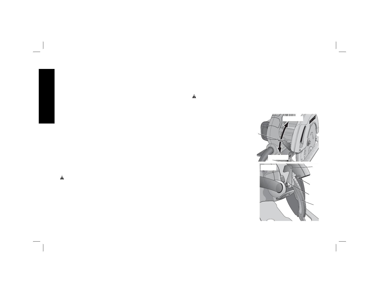
Cutting Depth Adjustment (Fig. 6–8)
WARNING: To reduce the risk of injury, turn unit off and
disconnect it from power source before installing and removing
accessories, before adjusting or when making repairs. An
accidental start-up can cause injury.
Your saw is equipped with a
LOOSEN
TIGHTEN
P
FIG. 6
carbide tipped saw blade for
long life and efficient cutting.
Setting the saw at the proper
cutting depth keeps blade
friction to a minimum, removes
sawdust from between the
blade teeth, results in cooler,
faster sawing and reduces the
chance of kickback.
1. Hold the saw firmly. Raise the
FIG. 7
R
Q
P
S
depth adjustment lever (P) to
loosen and move foot plate to
obtain the desired depth of
cut, as shown. Make sure the
depth adjustment lever has
been retightened (lowered)
before operating the saw.
2. Align the appropriate mark on
the depth adjustment strap (R)
with notch (Q) on the upper
blade guard. Your depth is set.
9
English
FIG. 8
3. For the most efficient cutting action using a carbide tipped saw
blade, set the depth adjustment so that about one half of a tooth
projects below the surface of the wood to be cut.
4. A method of checking for the correct cutting depth is shown in
Figure 8. Lay a piece of the material you plan to cut along the side
of the blade, as shown in the figure, and observe how much tooth
projects beyond the material.
ADJUSTING DEPTH ADJUSTMENT LEVER (FIG. 7)
It may be desirable to adjust the depth adjustment lever (P). It may
loosen in time and hit the foot plate before tighten ing.
To tighten the lever, follow the steps below.
1. Hold depth adjustment lever (P) and loosen the locknut (S).
2. Adjust the depth adjustment lever by rotating it in the desired
direction about 1/8 of a revolution.
3. Retighten nut.
Bevel Angle Adjustment (Fig. 9)
WARNING: To reduce the risk of injury, turn unit off and
disconnect it from power source before installing and removing
accessories, before adjusting or when making repairs. An
accidental start-up can cause injury.
On the front of the saw is a bevel angle adjustment mechanism (G)
which consists of an angle quadrant with a pointer (T) and a bevel
adjustment lever (F). The angle
F
G
TIGHTEN
LOOSEN
T
U
V
FIG. 9
quadrant allows for coarse
adjustment. To achieve better
accuracy in cutting, use the fine
adjustment markings located
on the pivot bracket (U). The full
range of bevel adjustment is 0
to 57 degrees. The pivot
bracket is graduated in
increments of 1degree.
1. To set the saw for a
bevel cut, raise the
bevel adjustment lever
(F) to loosen the bevel
adjustment.
2. Tilt the foot plate to the desired angle by aligning the pointer (T)
with the desired angle mark on the pivot bracket (U).
3. Retighten the bevel adjustment by lowering the lever.
Bevel Detent (Fig.9)
WARNING: To reduce the risk of injury, turn unit off and
disconnect it from power source before installing and removing
accessories, before adjusting or when making repairs. An
accidental start-up can cause injury.
The DWE575 and DWE575SB are equipped with a bevel detent
feature. As you tilt the foot plate you will hear a click and feel the foot
plate stop at both 22.5 and 45 degrees. If either of these is the desired
angle, retighten the lever (F) by lowering it. If you desire another angle,
continue tilting the foot plate until the coarse bevel pointer (V) or the
fine pointer (T) aligns with the desired mark.
10
English
Kerf Indicator (Fig. 10)
The front of the saw foot plate has a kerf indicator for vertical and bevel
cutting. This indicator enables you to guide the saw along cutting lines
penciled on the material being cut. The indicator lines up with the left
(inner) side of the saw blade which makes the slot or “kerf” cut by the
moving blade, fall to the right of the indicator. The markings on the
front of the foot plate are in increments of 1/8"(3.2mm).
FIG. 10
45˚
Cut Length Indicator (Fig. 11)
The markings on the side of the foot plate
FIG. 11
show the length of the slot being cut into
the material at the full depth of the cut. The
markings are in increments of 1/8" (3.2mm).
OPERATION
WARNING: To reduce the risk of
injury, turn unit off and disconnect it
from power source before installing
and removing accessories, before
adjusting or when making repairs. An
accidental start-up can cause injury.
Proper Hand Position (Fig.12)
WARNING: To reduce the risk of
FIG. 12
B
E
serious personal injury,
ALWAYS use
proper hand position as shown.
WARNING: To reduce the risk of
serious personal injury,
ALWAYS hold
securely in anticipation of a sudden
reaction.
Proper hand position requires one
hand on the main handle (B), with
the other hand on the auxiliary
handle (E).
Switch (Fig. 1)
Pull the trigger switch (A) to turn the motor on. Releasing the trigger
turns the motor off. This tool has no provision to lock the switch in the
on position, and the tool should never be locked on in any way.
Workpiece Support (Fig. 13–16)
WARNING: To reduce the risk of serious personal injury, support
the work properly and hold the saw firmly to prevent loss of control.
Figures 13 and 15 show proper sawing position. Figures 14 and 16
show an unsafe condition. Hands should be kept away from cutting
area, and power cord is positioned clear of the cutting area so that it
will not get caught or hung up on the work.
To avoid kickback, ALWAYS support board or panel NEAR the cut,
(Fig. 13 and 15). DON’T support board or panel away from the cut
(Fig.14 and 16). When operating the saw, keep the cord away from
the cutting area and prevent it from becoming hung up on the work
piece.
ALWAYS DISCONNECT SAW BEFORE MAKING ANY ADJUST MENTS!
Place the work with its “good” side—the one on which appearance is
11
English
most important—down. The saw cuts upward, so any splintering will be
on the work face that is up when you saw it.
FIG. 13
FIG. 14
Cutting
WARNING: Never attempt to use this tool by resting it upside
down on a work surface and bringing the material to the tool. Always
securely clamp the workpiece and bring the tool to the workpiece,
securely holding the tool with two hands as shown in Figure 15.
Place the wider portion of the saw foot plate on that part of the work
piece which is solidly supported, not on the section that will fall off when
the cut is made. As examples, Figure15 illustrates the RIGHT way to
cut off the end of a board. Always clamp work. Don’t try to hold short
pieces by hand! Remember to support cantilevered and overhanging
material. Use caution when sawing material from below.
FIG. 15 FIG. 16
Be sure saw is up to full speed before blade contacts material to be cut.
Starting saw with blade against material to be cut or pushed forward
into kerf can result in kickback. Push the saw forward at a speed which
allows the blade to cut without laboring. Hardness and toughness can
vary even in the same piece of material, and knotty or damp sections
can put a heavy load on the saw. When this happens, push the saw
more slowly, but hard enough to keep working without much decrease
in speed. Forcing the saw can cause rough cuts, inaccuracy, kickback,
and over-heating of the motor. Should your cut begin to go off the line,
don’t try to force it back on. Release the switch and allow blade to come
to a complete stop. Then you can withdraw the saw, sight anew, and
start a new cut slightly inside the wrong one. In any event, withdraw the
saw if you must shift the cut. Forcing a correction inside the cut can stall
the saw and lead to kickback.
IF SAW STALLS, RELEASE THE TRIGGER AND BACK THE SAW
UNTIL IT IS LOOSE. BE SURE BLADE IS STRAIGHT IN THE CUT
AND CLEAR OF THE CUTTING EDGE BEFORE RESTARTING.
12
English
As you finish a cut, release the trigger and allow the blade to stop
before lifting the saw from the work. As you lift the saw, the spring-
tensioned telescoping guard will automatically close under the blade.
Remember the blade is exposed until this occurs. Never reach under
the work for any reason. When you have to retract the telescoping
guard manually (as is necessary for starting pocket cuts) always use
the retracting lever.
NOTE: When cutting thin strips, be careful to ensure that small cutoff
pieces don’t hang up on inside of lower guard.
RIPPING (FIG. 17)
FIG. 17
W
Ripping is the process of cutting
wider boards into narrower
strips – cutting grain lengthwise.
Hand guiding is more difficult for
this type of sawing and the use
of D
EWALT DW3278 rip guide
(W) is recommended.
POCKET CUTTING (FIG. 18)
WARNING: Never tie the
blade guard in a raised position.
Never move the saw backwards
FIG. 18
E
when pocket cutting. This may
cause the unit to raise up off the
work surface which could cause
injury.
A pocket cut is one that is made in
a floor, wall or other flat surface.
1. Adjust the saw foot plate so the
blade cuts at desired depth.
2. Tilt the saw forward and rest
front of the foot plate on
material to be cut.
3. Using the lower guard lever, retract lower blade guard to an
upward position. Lower rear of foot plate until blade teeth almost
touch cutting line.
4. Release the blade guard (its contact with the work will keep it
in position to open freely as you start the cut). Remove hand
from guard lever and firmly grip auxiliary handle (E), as shown in
Figure 18. Position your body and arm to allow you to resist
kickback if it occurs.
5. Make sure blade is not in contact with cutting surface before
starting saw.
6. Start the motor and gradually lower the saw until its foot plate rests
flat on the material to be cut. Advance saw along the cutting line
until cut is completed.
7. Release trigger and allow blade to stop completely before
withdrawing the blade from the material.
8. When starting each new cut, repeat as above.
Kickback
When the saw blade becomes pinched or twisted in the cut, kickback
can occur. The saw is thrust rapidly back toward the operator. When
the blade is pinched or bound tightly by the kerf closing down, the
blade stalls and the motor reaction drives the unit backward. When the
blade becomes twisted or misaligned in the cut, the teeth at the back
edge of the blade can dig into the top surface of the wood causing
the blade to climb out of the kerf and jump back toward the operator.
Kickback is more likely to occur when any of the following conditions
exist.
1. IMPROPER WORKPIECE SUPPORT
A. Sagging or improper lifting of the cut off piece can cause
pinching of the blade and lead to kickback (Fig. 14).
13
English
B. Cutting through material supported at the outer ends only can
cause kickback. As the material weakens it sags, closing down
the kerf and pinching the blade.
C. Cutting off a cantilevered or overhanging piece of material from
the bottom up in a vertical direction can cause kickback. The
falling cut off piece can pinch the blade.
D. Cutting off long narrow strips (as in ripping) can cause kickback.
The cut off strip can sag or twist closing the kerf and pinching
the blade.
E. Snagging the lower guard on a surface below the material
being cut momentarily reduces operator control. The saw can
lift partially out of the cut increasing the chance of blade twist.
2. IMPROPER DEPTH OF CUT SETTING ON SAW
To make the most efficient cut, the blade should protrude only far
enough to expose 1/2 of a tooth as shown in Figure 9. This allows
the foot plate to support the blade and minimizes twisting and
pinching in the material. Refer to Cutting Depth Adjustment.
3. BLADE TWISTING (MISALIGNMENT IN CUT)
A. Pushing harder to cut through a knot, a nail, or a hard grain
area can cause the blade to twist.
B. Trying to turn the saw in the cut (trying to get back on the
marked line) can cause blade twist.
C. Over-reaching or operating the saw with poor body control (out
of balance), can result in twisting the blade.
D. Changing hand grip or body position while cutting can result in
blade twist.
E. Backing up the saw to clear blade can lead to twist if it is not
done carefully.
4. MATERIALS THAT REQUIRE EXTRA ATTENTION
A. Wet lumber
B. Green lumber (material freshly cut or not kiln dried)
C. Pressure treated lumber (material treated with preservatives or
anti-rot chemicals)
5. USE OF DULL OR DIRTY BLADES
Dull blades cause increased loading of the saw. To compensate,
an operator will usually push harder which further loads the unit
and promotes twisting of the blade in the kerf. Worn blades may
also have insufficient body clearance which increases the chance
of binding and increased loading.
6. LIFTING THE SAW WHEN MAKING BEVEL CUTS
Bevel cuts require special operator attention to proper cutting
techniques – especially guidance of the saw. Both blade angle to
the foot plate and greater blade surface in the material increase the
chance for binding and misalignment (twist) to occur.
7. RESTARTING A CUT WITH THE BLADE TEETH JAMMED
AGAINST THE MATERIAL
The saw should be brought up to full operating speed before
starting a cut or restarting a cut after the unit has been stopped
with the blade in the kerf. Failure to do so can cause stalling and
kickback.
Any other conditions which could result in pinching, binding, twisting,
or misalignment of the blade could cause kickback. Refer to
Additional Safety Instructions and Operation for procedures and
techniques that will minimize the occurrence of kickback.
MAINTENANCE
WARNING: To reduce the risk of injury, turn unit off and
disconnect it from power source before installing and removing
accessories, before adjusting or when making repairs. An
accidental start-up can cause injury.
14
English
Cleaning
WARNING: Blow dirt and dust out of all air vents with clean, dry air
at least once a week. To minimize the risk of eye injury, always wear
ANSI Z87.1 approved eye protection when performing this.
WARNING: Never use solvents or other harsh chemicals for cleaning
the non-metallic parts of the tool. These chemicals may weaken the
plastic materials used in these parts. Use a cloth dampened only with
water and mild soap. Never let any liquid get inside the tool; never
immerse any part of the tool into a liquid.
Lubrication
Self lubricating ball and roller bearings are used in the tool and
relubrication is not required. However, it is recommended that, once
a year, you take or send the tool to a service center for a thorough
cleaning, inspection and lubrication of the gear case.
Electric Brake (DWE575SB)
Your saw has an automatic electric brake which is designed to stop
the blade from coasting in about two seconds, after you release the
trigger switch. It is useful when making certain cuts in wood where a
coasting blade would result in a wide, imprecise cut.
Occasionally, the brake will not function properly and won’t stop the
saw in the 2 seconds discussed above. If this condition persists, turn
the saw on and off four or five times. If the brake still does not stop
the blade in about 2 seconds, the problem may be worn brushes.
Have the brushes replaced at a D
EWALT authorized service center.
Repairs
To assure product SAFETY and RELIABILITY, repairs, maintenance
and adjustment should be performed by a D
EWALT factory service
center, a D
EWALT authorized service center or other qualified service
personnel. Always use identical replacement parts. (Refer to Brushes
for brush replacement information.)
Brushes (Fig. 19)
WARNING: To reduce the risk of injury, turn unit off and
disconnect it from power source before installing and removing
accessories, before adjusting or when making repairs. An
accidental start-up can cause injury.
Inspect carbon brushes
D
X
X
FIG. 19
regularly by disconnecting the
tool from the power source,
removing the four end cap
screws (X) with a screwdriver,
then removing the end
cap (D).
Keep brushes clean and
sliding freely in their guides.
Always replace a used brush
in the same orientation in
the holder as it was prior to
removal. Carbon brushes have varying symbols stamped into their
sides, and if either brush is worn down to the line closest to the
spring, take the tool to a D
EWALT authorized service center for brush
assembly replacement. Use only identical D
EWALT brushes. Always
replace the end cap after inspecting or servicing brushes. The tool
should be allowed to “run in” (run at no load without a blade) for 5
minutes before use to seat new brushes.
While “running in” DO NOT TIE, TAPE, OR OTHERWISE LOCK THE
TRIGGER SWITCH ON. HOLD BY HAND ONLY.
Foot Plate Adjustment
WARNING: To reduce the risk of injury, turn unit off and
disconnect it from power source before installing and removing
accessories, before adjusting or when making repairs. An
accidental start-up can cause injury.
15
English
Your foot plate has been factory set to assure that the blade is
perpendicular to the foot plate. If after extended use you need to
re-align the blade, follow the directions below:
ADJUSTING FOR 90 DEGREE CUTS (FIG. 1, 20)
1. Return the saw to
FIG. 20
Y
0degrees bevel.
2. Place the saw on its side,
and retract the lower
guard.
3. Set the depth of cut
at approximately 2"
(51mm).
4. Loosen the bevel
adjustment lever (F).
Place a square against
the blade and the
foot plate as shown in
Figure20.
5. Using a hex wrench, turn the set screw (Y) on the underside of the
foot plate until the blade and the foot plate are both in flush contact
with the square. Retighten the bevel adjustment lever.
ADJUSTING BEVEL ADJUSTMENT LEVER
It may be desirable to adjust the
FIG. 21
Z
F
bevel adjustment lever. It may
loosen in time and hit the foot plate
before tighten ing.
To tighten the lever, follow the
steps below.
1. Hold bevel adjustment lever (F)
and loosen the locknut (Z).
2. Adjust the bevel adjustment lever by rotating it in the desired
direction about 1/8 of a revolution.
3. Retighten nut.
Blades
A dull blade will cause inefficient cutting, overload on the saw motor,
excessive splintering and increase the possibility of kickback. Change
blades when it is no longer easy to push the saw through the cut,
when the motor is straining, or when excessive heat is built up in the
blade. It is a good practice to keep extra blades on hand so that sharp
blades are available for immediate use. Dull blades can be sharpened
in most areas; see SAWS-SHARPENING in the yellow pages.
Hardened gum on the blade can be removed with kerosene,
turpentine, or oven cleaner. Anti-stick coated blades can be used
in applications where excessive build-up is encountered, such as
pressure treated and green lumber.
RECOMMENDED BLADE TYPES
COMBINATION FRAMING 5/8" Round arbor, 24 teeth
All purpose fast rip and cross cuts.
PRESSURE TREATED/ 5/8" Round arbor, 20 teeth
WET LUMBER Coated - Resistant to gum build-up
EXTREME DURABILITY 5/8" Round arbor, 18 teeth
Coated, rock carbide
FINISHING 5/8" Round arbor, 36 teeth
More teeth for fi ner fi nish cuts.
FAST CUT FRAMING 5/8" Round arbor, 18 teeth
Fastest blade for rips and cross cuts
16
English
Accessories
WARNING: Since accessories, other than those offered by DEWALT,
have not been tested with this product, use of such accessories with
this tool could be hazardous. To reduce the risk of injury, only D
EWALT,
recommended accessories should be used with this product.
Recommended accessories for use with your tool are available at
extra cost from your local dealer or authorized service center. If you
need assistance in locating any accessory, please contact D
EWALT
Industrial Tool Co., 701 East Joppa Road, Baltimore, MD 21286, call
1-800-4-D
EWALT (1-800-433-9258) or visit our website www.dewalt.
com.
DO NOT USE WATER FEED ATTACHMENTS WITH THIS SAW.
VISUALLY EXAMINE CARBIDE BLADES BEFORE USE. REPLACE IF
DAMAGED.
Three Year Limited Warranty
DEWALT will repair, without charge, any defects due to faulty materials
or workmanship for three years from the date of purchase. This
warranty does not cover part failure due to normal wear or tool abuse.
For further detail of warranty coverage and warranty repair information,
visit www.dewalt.com or call 1-800-4-D
EWALT (1-800-433-9258).
This warranty does not apply to accessories or damage caused where
repairs have been made or attempted by others. This warranty gives
you specific legal rights and you may have other rights which vary in
certain states or provinces.
In addition to the warranty, D
EWALT tools are covered by our:
1 YEAR FREE SERVICE
D
EWALT will maintain the tool and replace worn parts caused by
normal use, for free, any time during the first year after purchase.
90 DAY MONEY BACK GUARANTEE
If you are not completely satisfied with the performance of your
D
EWALT Power Tool, Laser, or Nailer for any reason, you can return it
within 90 days from the date of purchase with a receipt for a full refund
– no questions asked.
LATIN AMERICA: This warranty does not apply to products sold in
Latin America. For products sold in Latin America, see country specific
warranty information contained either in the packaging, call the local
company or see website for warranty information.
FREE WARNING LABEL REPLACEMENT: If your warning labels
become illegible or are missing, call 1-800-4-D
EWALT (1-800-433-
9258) for a free replacement.
DEWALT Industrial Tool Co., 701 Joppa Road, Baltimore, MD 21286
(DEC11) Part No. N143176 DWE575, DWE575SB Copyright © 2011 D
EWALT
The following are trademarks for one or more D
EWALT power tools: the yellow and black color scheme; the “D” shaped air intake grill;
the array of pyramids on the handgrip; the kit box configuration; and the array of lozenge-shaped humps on the surface of the tool.
  • Page 1 1
  • Page 2 2
  • Page 3 3
  • Page 4 4
  • Page 5 5
  • Page 6 6
  • Page 7 7
  • Page 8 8
  • Page 9 9
  • Page 10 10
  • Page 11 11
  • Page 12 12
  • Page 13 13
  • Page 14 14
  • Page 15 15
  • Page 16 16
  • Page 17 17
  • Page 18 18
  • Page 19 19
  • Page 20 20
  • Page 21 21
  • Page 22 22
  • Page 23 23
  • Page 24 24
  • Page 25 25
  • Page 26 26
  • Page 27 27
  • Page 28 28
  • Page 29 29
  • Page 30 30
  • Page 31 31
  • Page 32 32
  • Page 33 33
  • Page 34 34
  • Page 35 35
  • Page 36 36
  • Page 37 37
  • Page 38 38
  • Page 39 39
  • Page 40 40
  • Page 41 41
  • Page 42 42
  • Page 43 43
  • Page 44 44
  • Page 45 45
  • Page 46 46
  • Page 47 47
  • Page 48 48
  • Page 49 49
  • Page 50 50
  • Page 51 51
  • Page 52 52
  • Page 53 53
  • Page 54 54
  • Page 55 55
  • Page 56 56
  • Page 57 57
  • Page 58 58
  • Page 59 59
  • Page 60 60

DeWalt DWE575 User manual

Category
Circular saws
Type
User manual
This manual is also suitable for

Ask a question and I''ll find the answer in the document

Finding information in a document is now easier with AI

in other languages