Operating Instructions Gravity Feed Spray Gun
3
www.chpower.com
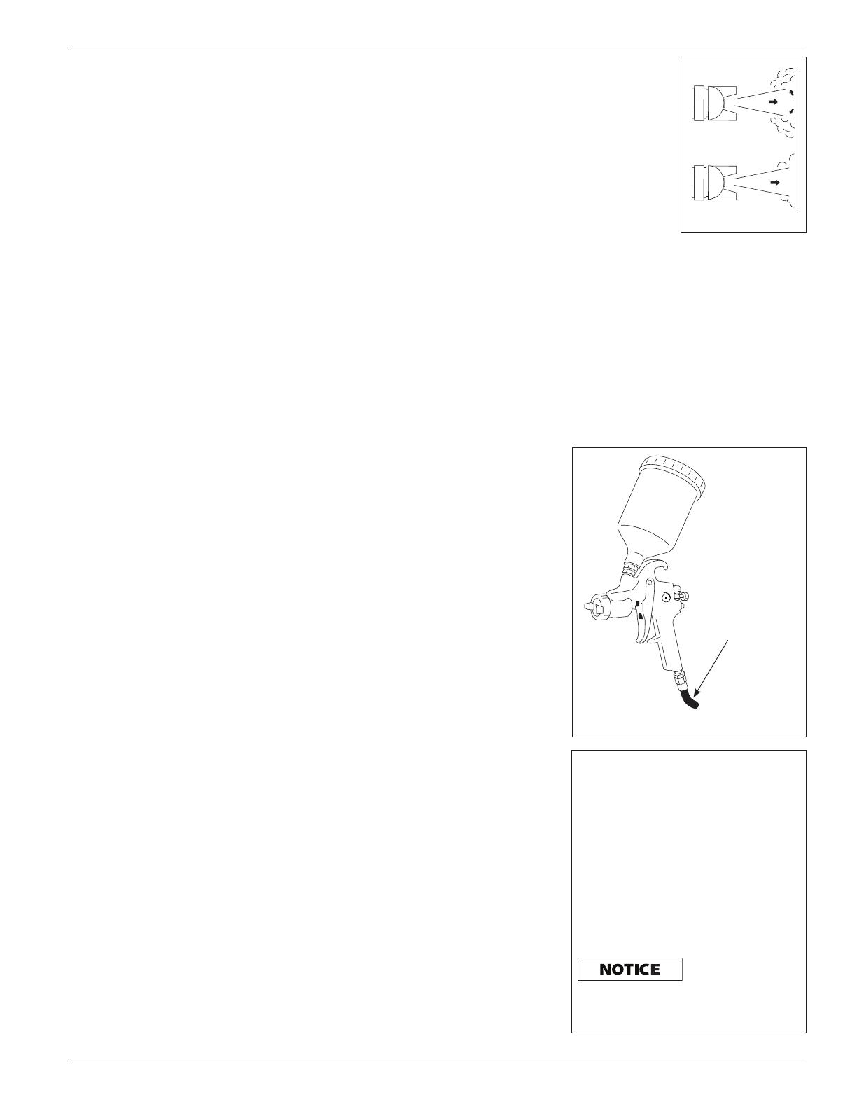
produced which
increases control
and reduces
bounceback and
overspray (See
Figure 1). For
these reasons,
HVLP is also well
suited for spraying
parts with
recessed areas.
Spray Gun Setup
The pressure for atomization is
controlled at the air source. The amount
of fluid is adjusted by the fluid control
knob, the paint viscosity and the air
pressure.
The gravity feed cup screws onto the
top of the gun body creating a positive
fluid pressure in the nozzle (See
Figure 2).
Introduction
The spray gun is a vital link in any
finishing application. In addition to
operating the spray gun properly,
techniques of surface preparation and
paint preparation must be understood.
These instructions will explain the
differences among various spray
technologies and serve as a guide in
the proper operation and techniques
of spray painting. Refer to the
Replacement Parts Manual for model
specific information.
SPRAY GUN TERMS
Atomization – Conversion of bulk
liquid to spray droplets (mist).
Bleeder – In this mode, air passes
continuously through the gun whether
spraying or not. This mode is generally
used when the air is supplied by a
continuously running compressor that
does not have a tank.
Bleeder / Non-Bleeder – Indicates
whether air flows through the gun
continuously or as the trigger is pulled.
External Mix – Process where the air
and paint are mixed just after leaving
the nozzle. This type of mix should be
used for fast drying paints and when a
high quality finish is needed.
Feed – Method used to bring paint into
the gun for spraying.
Fluid Control Knob – Used to control
the amount of paint being mixed with
air.
Gravity Feed – Method of paint feed
similar to the siphon feed method.
However, the cup is inverted to create a
positive fluid pressure at the nozzle.
Internal Mix – Process where the air
and paint are mixed inside the air cap
just before being sprayed. This method
is best for heavy bodied, slow drying
paints and can only be used with the
pressure feed method. Do not use fast
drying paints with internal mix. The
paint will dry inside and quickly clog the
air cap.
Mix – The mixing of paint and air when
spraying.
Non-Bleeder – In this mode, air
flows only when the trigger is pulled.
This type of operation is used with a
compressor equipped with a tank or
with a large factory air system.
Paint Tank – An auxiliary pressurized
paint reservoir that allows continuous
spraying of large amounts of paint
without stopping for refills as with a
canister. It also allows using the spray
gun at any angle without causing paint
to drip.
Pattern Control Knob – Used to form
the proper pattern (size and shape) of
paint as it is sprayed from the gun to
the workpiece.
Pressure Feed – Method of paint
feed where a canister or paint tank is
pressurized to force paint to the gun.
Either internal or external mix air caps
are used with this method. Pressure
feed is generally used for spraying
heavy bodied paints or for large size
projects.
Siphon Feed – Method of paint feed
where atmospheric pressure creates a
partial vacuum to siphon paint to the
gun. Only external mix air caps are used
with this method. Siphon feed is used
with light bodied paints.
Viscosity – A measurement of the
resistance to the flow of liquids.
CONVENTIONAL VS. HVLP
Conventional spray guns use a much
higher air cap pressure to atomize paint
than HVLP spray guns. This results in
more overspray and a lower transfer
efficiency.
HVLP, electrostatic and airless processes
are currently the only compliant spray
methods that meet the strict 65%
transfer efficiency criteria required by
some air quality management districts.
This enhanced transfer efficiency
results in a significant material savings
compared to conventional spraying.
Check local, state and national
regulations that may be in effect before
performing any spraying operations.
HVLP spraying is a growing trend
in the finishing industry due to
its environmental friendliness. By
definition, dynamic air pressures in the
air cap must be 10 psi or less to qualify
as HVLP. A soft, low velocity pattern is
Figure 1
Conventional
HVLP
Figure 2 - Gravity Feed Cup Set-up
Filtered,
Regulated
Air Source
WATER / OIL IN COMPRESSED AIR
All compressor pumps discharge some
condensed water, oil or contaminates
with the compressed air.
IMPORTANT: This condensation
will cause “fish eyes” to appear in
the paint job. Install appropriate
water/oil removal equipment and
controls as necessary for the intended
application. Locate filter as close to
spray gun as possible.
Failure to install
appropriate
water / oil removal equipment may
result in damage to machinery or
workpiece.


