
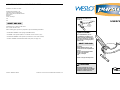
CAUTION
Read all precautions and in-
structions in this manual before
using this equipment. Save this
manual for future reference.
USER’S MANUAL
Model No. WLEMEX14710
Serial No. __________________
www.weslo.com
Visit our website at
QUESTIONS?
As a manufacturer, we are
committed to providing com-
plete customer satisfaction. If
you have questions, or if there
are missing or damaged parts,
please call:
Or write:
ICON Health & Fitness, Ltd.
Customer Service Department
Unit 4
Revie Road Industrial Estate
Revie Road, Beeston
Leeds, LS118JG
UK
email: [email protected]
08457 089 009
Serial
Number
Decal
Part No. 180954 R1101A Printed in China © 2001 ICON Health & Fitness, Inc.
If you encounter any difficulties with this product, or if you need to order replacement parts, call the ICON Health
& Fitness, Ltd. office, or write:
ICON Health & Fitness, Ltd.
Customer Service Department
Unit 4, Revie Road Industrial Estate
Revie Road
Beeston
Leeds, LS118JG
UK
Tel:
Outside the UK: 0 (044) 113 387 7133
Fax: 0 (044) 113 387 7125
When ordering parts, please be prepared to give the following information:
• the MODEL NUMBER of the product (WLEMEX14710)
• the NAME of the product (WESLO
®
PURSUIT RC375 exercise cycle)
• the SERIAL NUMBER of the product (see the front cover of this manual)
• the KEY NUMBER and DESCRIPTION of the parts (see page 10).
08457 089 009
ORDERING REPLACEMENT PARTS

2 11
TABLE OF CONTENTS
IMPORTANT PRECAUTIONS . . . . . . . . . . . . . . . . . . . . . . . . . . . . . . . . . . . . . . . . . . . . . . . . . . . . . . . . . . . . .2
BEFORE YOU BEGIN . . . . . . . . . . . . . . . . . . . . . . . . . . . . . . . . . . . . . . . . . . . . . . . . . . . . . . . . . . . . . . . . . . .3
ASSEMBLY . . . . . . . . . . . . . . . . . . . . . . . . . . . . . . . . . . . . . . . . . . . . . . . . . . . . . . . . . . . . . . . . . . . . . . . . . . .4
HOW TO USE THE EXERCISE CYCLE . . . . . . . . . . . . . . . . . . . . . . . . . . . . . . . . . . . . . . . . . . . . . . . . . . . . . .6
STORAGE AND TROUBLE-SHOOTING . . . . . . . . . . . . . . . . . . . . . . . . . . . . . . . . . . . . . . . . . . . . . . . . . . . . .7
CONDITIONING GUIDELINES . . . . . . . . . . . . . . . . . . . . . . . . . . . . . . . . . . . . . . . . . . . . . . . . . . . . . . . . . . . . .9
PART LIST . . . . . . . . . . . . . . . . . . . . . . . . . . . . . . . . . . . . . . . . . . . . . . . . . . . . . . . . . . . . . . . . . . . . . . . . . . .10
EXPLODED DRAWING . . . . . . . . . . . . . . . . . . . . . . . . . . . . . . . . . . . . . . . . . . . . . . . . . . . . . . . . . . . . . . . . .11
ORDERING REPLACEMENT PARTS . . . . . . . . . . . . . . . . . . . . . . . . . . . . . . . . . . . . . . . . . . . . . . . .Back Cover
23
20
20
19
37
21
39
34
36
36
41
42
33
32
20
20
14
26
38
40
35
43
17
15
33
54
18
61
46
45
45
60
44
29
29
28
60
16
47
22
31
30
29
28
3
3
29
44
46
45
46
45
9
10
9
8
9
11
2
4
37
48
63
64
23
27
24
62
25
13
58
59
5
6
6
5
7
1
55
56
57
53
52
51
49
35
42
50
41
43
40
24
46
12
58
59
EXPLODED DRAWING—Model No. WLEMEX14710 R1101A
1. Read all instructions in this manual before
using the exercise cycle.
2. It is the responsibility of the owner to ensure
that all users of the exercise cycle are ade-
quately informed of all warnings and precau-
tions.
3. The exercise cycle is intended for home use
only. Do not use the exercise cycle in a com-
mercial, rental, or institutional setting.
4. Place the exercise cycle on a level surface.
Cover the floor beneath the exercise cycle to
protect the floor or carpet.
5. Inspect and properly tighten all parts regular-
ly. Make sure that the drive belt is properly
adjusted (see page 8). Replace any worn
parts immediately.
6. Keep children under age 12 and pets away
from the exercise cycle at all times.
7. The exercise cycle should not be used by
persons weighing more than 115 kg (250 lbs.).
8. Do not wear loose clothing that could
become caught on the exercise cycle. Always
wear athletic shoes for foot protection.
9. Keep hands and feet away from moving parts.
10.When adjusting the seat, make sure that the
shaft of the seat knob is inserted into one of
the holes in the seat frame (refer to page 6).
11. If you feel faint, dizzy, or short of breath
whilst exercising, stop immediately and begin
cooling down.
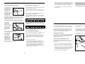
12.The warning decal shown below is found on
the exercise cycle in the indicated location. If
the decal is missing or illegible, call 08457
089 009 and order a free replacement decal.
Apply the decal in the location shown.
IMPORTANT PRECAUTIONS
WARNING:
To reduce the risk of serious injury, read the following important precautions
before using the exercise cycle.

10 3
PART LIST—Model No. WLEMEX14710 R1101A
Note: “#” refers to a non-illustrated part. Specifications are subject to change without notice. See the back cover
of this manual for information about ordering replacement parts.
Key No. Qty. Description Key No. Qty. Description
BEFORE YOU BEGIN
Congratulations for selecting the new WESLO
®
PURSUIT RC375 exercise cycle. Cycling is one of the
most effective exercises for increasing cardiovascular
fitness, building endurance, and toning the entire
body. The PURSUIT RC375 lets you enjoy this health-
ful exercise in the convenience and privacy of your
home.
For your benefit and safety, read this manual care-
fully before using the exercise cycle. If you have
questions after reading the manual, please call our
Customer Service Department at 08457 089 009. To
help us assist you, please note the product model
number and serial number before calling. The model
number is WLEMEX14710. The serial number can be
found on a decal attached to the exercise cycle (see
the front cover of this manual for the location).
Before reading further, please review the drawing
below and familiarise yourself with the parts that are
labeled.
A cool-down, with 5 to 10 minutes of stretching. This
will increase the flexibility of your muscles and will
help to prevent post-exercise problems.
EXERCISE FREQUENCY
To maintain or improve your condition, plan three work-
outs each week, with at least one day of rest between
workouts. After a few months of regular exercise, you
may complete up to five workouts each week, if
desired. CAUTION: Be sure to progress at your
own pace and avoid overdoing it. Incorrect or
excessive training may result in injury to your
health.
Remember, the key to success is make exercise a
regular and enjoyable part of your everyday life.
1 1 Seat
2 1 Handlebar Bracket
3 4 Seat Screw
4 1 Rear Stabiliser
5 2 Foam Grip
6 2 Handlebar Cap
7 1 Handlebar
8 1 Handlebar Lever
9 4 Handlebar Washer
10 1 Handlebar Lock Washer
11 2 Handlebar Bolt
12 1 Left Side Shield
13 1 Right Side Shield
14 1 Right Pedal
15 1 Console
16 1 Frame
17 1 Resistance Control/Cable
18 1 Resistance Control Screw
19 1 Front Stabiliser
20 4 Stabiliser Cap
21 1 Drive Belt
22 1 Seat Knob
23 1 Crank Assembly
24 1 Crank/Pulley
25 1 Left Pedal
26 1 Idler Jam Nut
27 2 Crank Nut
28 2 Frame Bolt
29 4 Frame Washer
30 1 Seat Frame
31 1 Plastic Bushing
32 2 Reed Switch Screw
33 1 Reed Switch/Wire
34 1 Idler Bracket
35 2 Axle Locknut
36 2 Idler Washer
37 4 Carriage Bolt
38 1 Idler Bolt
39 1 Spring
40 2 Eyebolt
41 2 Axle washer
42 2 Eyebolt Bracket
43 2 Adjustment Nut
44 2 Frame Locknut
45 4 Curved Washer
46 4 Acorn Nut
47 2 Lock Pin
48 2 Backrest Screw
49 1 Flywheel
50 1 Axle
51 1 Spacer
52 1 Resistance Spring
53 1 Resistance Strap
54 1 Strap Clamp
55 1 Resistance Bolt
56 1 Resistance Washer
57 1 Resistance Locknut
58 4 Large Side Shield Screw
59 2 Small Side Shield Screw
60 2 Frame Cap
61 1 Clamp Screw
62 1 Backrest
63 1 Backrest Frame Cap
64 1 Backrest Frame
# 1 User’s Manual
Pedal
Lock Pin
Stabiliser
Console
Resistance Control
Handlebar
Handlebar Lever
Lock Pin
Seat Knob
Seat
Frame
Backrest
WARNING:Before beginning this or any exercise program, consult your physician. This
is especially important for persons over the age of 35 or persons with pre-existing health problems.
Read all instructions before using. ICON assumes no responsibility for personal injury or property
damage sustained by or through the use of this product.

94
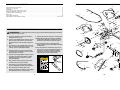
ASSEMBLY
Place all parts of the exercise cycle in a cleared area and remove the packing materials. Do not dispose of the
packing materials until assembly is completed. Assembly requires the included allen wrench ,
a phillips screwdriver , and two adjustable wrenches .
2
37
19
20
45
46
45
16
46
1. Remove the Lock Pin (47) from the bracket at the
rear of the Seat Frame (30). Carefully unfold the
exercise cycle until the Frame (16) and the Seat
Frame are in the position shown.
Insert the Lock Pin (47) into the hole in the indicat-
ed bracket on the Frame (16).
1
30
47
16
2. Identify the Front Stablizer (19), which is the narrow-
er Stabilizer. Insert a Stabiliser Cap (20) into each
end of the Front Stabiliser. Note: Stabiliser Caps
may already be attached.
Attach the Front Stabiliser (19) to the indicated brack-
et on the Frame (16) with two Carriage Bolts (37),
two Curved Washers (45), and two Acorn Nuts (46).
3. Insert a Stabiliser Cap (20) into each end of the
Rear Stabiliser (4). Note: Stabiliser Caps may
already be attached.
Attach the Rear Stabiliser (4) to the indicated brack-
et on the Seat Frame (30) with two Carriage Bolts
(37), two Curved Washers (45), and two Acorn Nuts
(46).
3
46
37
20
46
30
45
45
4
The following guidelines will help you to plan your
exercise program. Remember that proper nutrition and
adequate rest are essential for successful results.
EXERCISE INTENSITY
Whether your goal is to burn fat or to strengthen your
cardiovascular system, the key to achieving the
desired results is to exercise with the proper intensity.
The proper intensity level can be found by using your
heart rate as a guide. The chart below shows recom-
mended heart rates for fat burning, maximum fat burn-
ing, and cardiovascular (aerobic) exercise.
To find the proper heart rate for you, first find your age
at the bottom of the chart (ages are rounded off to the
nearest ten years). Next, find the three numbers
above your age. The three numbers are your “training
zone.” The lowest number is the recommended heart
rate for fat burning, the middle number is the recom-
mended heart rate for maximum fat burning, and the
highest number is the recommended heart rate for
aerobic exercise.
Fat Burning
To burn fat effectively, you must exercise at a relative-
ly low intensity level for a sustained period of time.
During the first few minutes of exercise, your body
uses easily accessible carbohydrate calories for ener-
gy. Only after the first few minutes of exercise does
your body begin to use stored fat calories for energy. If
your goal is to burn fat, adjust the intensity of your
exercise until your heart rate is near the lowest num-
ber in your training zone as you exercise. For maxi-
mum fat burning, adjust the intensity of your exercise
until your heart rate is near the middle number in your
training zone as you exercise.
Aerobic Exercise
If your goal is to strengthen your cardiovascular sys-
tem, your exercise must be “aerobic.” Aerobic exercise
is activity that requires large amounts of oxygen for
prolonged periods of time. This increases the demand
on the heart to pump blood to the muscles, and on the
lungs to oxygenate the blood. For aerobic exercise,
adjust the intensity of your exercise until your heart
rate is near the highest number in your training zone
as you exercise.
HOW TO MEASURE YOUR HEART RATE
To measure your heart
rate, first exercise for
at least four minutes.
Then, stop exercising
and place two fingers
on your wrist as
shown. Take a six-sec-
ond heartbeat count,
and multiply the result
by 10 to find your heart rate. For example, if your six-
second heartbeat count is 14, your heart rate is 140
beats per minute. (A six-second count is used
because your heart rate will drop rapidly when you
stop exercising.)
WORKOUT GUIDELINES
Each workout should include the following three parts:
A warm-up, consisting of 5 to 10 minutes of stretching
and light exercise. A proper warm-up increases your
body temperature, heart rate, and circulation in prepa-
ration for exercise.
Training zone exercise, consisting of 20 to 30 min-
utes of exercising with your heart rate in your training
zone. (During the first few weeks of your exercise pro-
gram, do not keep your heart rate in your training
zone for longer than 20 minutes.)
A cool-down, with 5 to 10 minutes of stretching. This
will increase the flexibility of your muscles and will
help to prevent post-exercise problems.
CONDITIONING GUIDELINES
WARNING:Before beginning this
or any exercise program, consult your physi-
cian. This is especially important for individu-
als over the age of 35or individuals with pre-
existing health problems.

58
6
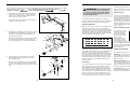
4. Loosen, but do not remove, the Handlebar Lever (8)
and the two Handlebar Bolts (11) that hold the
Handlebar Bracket (2) in place.
Slide the Handlebar (7) through the Handlebar
Bracket (2) until the Handlebar is in the position
shown. Note: If it is difficult to slide the Handlebar
into position, remove the Handlebar Bracket.
After the Handlebar (7) is in position, tighten the
Handlebar Lever (8) and the two Handlebar Bolts (11).
5. Attach the Seat (1) to the indicated brackets on the
Seat Frame (30) with the four Seat Screws (3).
6. Press the Backrest Frame Cap (63) into the
Backrest Frame (64). Attach the Backrest (62) to the
Backrest Frame with two Backrest Screws (48).
Attach the Backrest Frame (64) to the indicated
bracket on the Seat Frame (30) with a Frame Bolt
(28), two Frame Washers (29), and a Frame
Locknut (44).
Hold the Backrest Frame (64) in an upright position.
Insert a Lock Pin (47) into the indicated holes in the
bracket on the Seat Frame (30) and the Backrest
Frame.
5
5
7
8
2
9
10
11
30
9
63
64
48
62
30
29
28
47
29
44
7
7. The Console (15) requires two 1,5 V batteries (not
included). Alkaline batteries are recommended.
Insert two batteries into the battery compartment in
the back of the Console. Make sure that the nega-
tive ends of the batteries (marked “—”) are
touching the springs in the battery compartment.
Slide the Console (15) onto the console bracket.
Connect the Reed Switch Wire (33) to the jack on
the back of the Console (15) through the hole in the
bracket on the Frame (16).
Identify the Left Pedal (25), which is marked with an
“L.” Using an adjustable wrench, tighten the Left
Pedal counterclockwise into the left arm of the
Crank (24). Next, tighten the Right Pedal (not
shown) clockwise into the right arm on the Crank.
8. Make sure that all parts are properly tightened
before you use the exercise cycle.
Hole
15
25
24
16
33
Console
Bracket
5
1
30
3
4
HOW TO ADJUST THE RESISTANCE STRAP
If there is not enough pedaling resistance when the
resistance control is turned to the highest setting, the
resistance strap may need to be adjusted. Follow the
steps below to adjust the resistance strap.
1. Turn the resistance control to the lowest setting.
2. Locate the strap clamp behind the console and
open it.
3. Grip the end of the resistance strap (not shown)
and pull it slightly. While holding the resistance
strap, fully close the strap clamp. Turn the pedals
for a moment to make sure that there is not too
much resistance.
HOW TO ADJUST THE DRIVE BELT
If the drive belt causes excessive noise or slips as
you pedal, follow the steps below to adjust the drive
belt.
1. Remove the left and right pedals. Then, remove
the screws that hold the side shields in place;
make sure to note the location of each screw.
Remove both side shields.
2. Press down on the center of the drive belt between
the front and rear pulleys. There should be from
1/4” to 1/2” of movement in the center of the
drive belt.
If the drive belt is properly adjusted, go to step 4.
3. If the drive belt needs to be adjusted, loosen the
indicated locknut on each side of the flywheel.
To tighten the drive belt, turn the adjustment nuts
clockwise; to loosen the drive belt, turn the adjust-
ment nuts counterclockwise. Make sure that the fly-
wheel is straight and tighten the locknuts.
4. Reattach the side shields and the pedals.
Side
Shields
Screws
Strap
Clamp
Console
Resistance
Control
Flywheel
Adjustment
Nuts
Drive Belt
Locknut

76
Inspect and properly tighten all parts of the exercise
cycle regularly. Replace any worn parts immediately.
To clean the exercise cycle, use a soft, damp cloth.
Make sure to keep liquids away from the console,
keep the console out of direct sunlight, and remove
the batteries when storing the exercise cycle.
BATTERY REPLACEMENT
If the console does not function properly, the batteries
should be replaced. See assembly step 7 on page 5.
In addition, make sure that the reed switch wire is
plugged into the console.
HOW TO STORE THE EXERCISE CYCLE
When the exercise cycle is not in use, it can be
adjusted to the storage position. Follow the instruc-
tions below.
1. Loosen the Seat Knob (22) and slide the Seat
Frame (30) fully forward. Retighten the Seat Knob.
2. Remove the Lock Pin (not shown) that holds the
Backrest Frame (64) in the upright position and fold
the Backrest (62) down onto the Seat (1). Reinsert
the Lock Pin to hold the Backrest in place.
If desired, remove the Handlebar (7).
3. Remove the Lock Pin (47) that holds the Frame
(16) in position.
4. Carefully fold the exercise cycle. Line up the brack-
et on the Seat Frame (30) with the welded tube on
the Frame (16). Then, insert the Lock Pin (47)
through the bracket and the welded tube.
Store the exercise cycle indoors, away from mois-
ture and dust.
STORAGE AND TROUBLE-SHOOTING
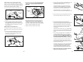
HOW TO USE THE EXERCISE CYCLE
HOW TO ADJUST THE SEAT FRAME
To adjust the seat
frame to the most
comfortable posi-
tion, first turn the
seat knob coun-
terclockwise to
loosen it. Next, lift
and hold the seat
knob while sliding
the seat frame
forward or back-
ward to the desired position. Release the seat knob,
and slide the seat frame slightly until you feel the seat
knob snap into one of the adjustment holes. Then,
retighten the seat knob.
HOW TO ADJUST THE PEDALING RESISTANCE
To increase the
pedaling resis-
tance as you
exercise, turn the
resistance control
counterclockwise;
to decrease the
resistance, turn
the control clock-
wise.
ADJUSTING THE HANDLEBAR
The handlebar
can be adjusted
to the position
that is the most
comfortable. To
adjust the handle-
bar, first open the
handlebar lever.
Pivot the handle-
bar to the desired
position, and then close the lever.
DESCRIPTION OF THE CONSOLE
The console features five modes that provide exercise
feedback during your workouts:
• Scan—Displays the time, speed, distance, and calo-
rie modes, for four seconds each, in a repeating
cycle.
• Time—Displays the elapsed time. Note: If you stop
pedaling, the time mode will pause.
• Speed—Displays your speed. Use the chart below
to convert between kilometres per hour and miles
per hour.
• Distance—Displays the distance you have pedaled.
Use the chart below to convert between kilometres
and miles.
• Calorie—Displays the approximate number of
Calories you have burned.
HOW TO OPERATE THE CONSOLE
Note: The console requires two 1,5 V batteries. Refer
to step 7 on page 5 for installation instructions.
1. To turn on the power, press the console button or
begin pedaling. The entire display will appear for
two seconds; the console will then be ready for
use.
2. Select one of the modes:
Scan mode—When the power is turned on, the
scan mode will automatically be selected. One
mode arrow will show that the scan mode is select-
ed, and a second mode arrow will show which
mode is displayed. Note: If a different mode is
selected, you can select the scan mode by repeat-
edly pressing the console button.
Seat
Frame
Seat
Knob
Resistance
Control
Handlebar
Lever
Time, speed, distance, or calorie mode—To select
one of these modes for continuous display, press the
console button until the desired mode is displayed.
Make sure that the scan mode is not selected.
3. To reset the display, press the console button for
three seconds.
4. To turn off the power, wait for about four minutes.
Note: The monitor has an “auto-off” feature. If
the pedals are not moved and the console button
is not pressed for four minutes, the power will
turn off automatically to conserve the batteries.
22
16
30
1
47
62
64
Welded
Tube
Bracket
7
-
 1
1
-
 2
2
-
 3
3
-
 4
4
-
 5
5
-
 6
6


Weslo WLEMEX1471 User manual
- Type
- User manual
- This manual is also suitable for
Ask a question and I''ll find the answer in the document
Finding information in a document is now easier with AI
Related papers
-
Weslo WLEVEX71209.0 User manual
-
Weslo WLEVEX19831 User manual
-
Weslo Pursuit 202 User manual
-
-
-
-
Weslo Pursuit 102 User manual
-
-
-
Other documents
-
ProForm PFEVEX6283 Owner's manual
-
-
-
-
NordicTrack NTEVEX99830 User manual
-
-
-
-
-