Page is loading ...

Manual
WAGO-I/O-SYSTEM 750 XTR
750-486/040-000
4AI 0/4
-20mA NE43 Ex i XTR
4
-channel analog input; 0/4 … 20 mA; NE43;
intrinsically safe; extreme
Version 1.0.0

2 WAGO-I/O-SYSTEM 750 XTR
750-486/040-000 4AI 0/4-20mA NE43 Ex i XTR
Manual
Version 1.0.0
© 2018 WAGO Kontakttechnik GmbH & Co. KG
All rights reserved.
WAGO Kontakttechnik GmbH & Co. KG
Hansastraße 27
D-32423 Minden
Phone: +49 (0) 571/8 87 – 0
Fax: +49 (0) 571/8 87 – 1 69
Web: http://www.wago.com
Technical Support
Phone: +49 (0) 571/8 87 – 5 55
Fax: +49 (0) 571/8 87 – 85 55
Every conceivable measure has been taken to ensure the accuracy and
completeness of this documentation. However, as errors can never be fully
excluded, we always appreciate any information or suggestions for improving the
documentation.
We wish to point out that the software and hardware terms as well as the
trademarks of companies used and/or mentioned in the present manual are
generally protected by trademark or patent.
WAGO is a registered trademark of WAGO Verwaltungsgesellschaft mbH.

WAGO-I/O-SYSTEM 750 XTR Table of Contents 3
750-486/040-000 4AI 0/4-20mA NE43 Ex i XTR
Manual
Version 1.0.0
Table of Contents
1 Notes about this Documentation ............................................................. 6
1.1 Validity of this Documentation................................................................. 6
1.2 Copyright ................................................................................................ 6
1.3 Symbols ................................................................................................. 7
1.4 Number Notation .................................................................................... 9
1.5 Font Conventions ................................................................................... 9
2 Important Notes ...................................................................................... 10
2.1 Legal Bases .......................................................................................... 10
2.1.1 Subject to Changes .......................................................................... 10
2.1.2 Personnel Qualifications .................................................................. 10
2.1.3 Use of the WAGO-I/O-SYSTEM 750 in Compliance with
Underlying Provisions ...................................................................... 10
2.1.4 Technical Condition of Specified Devices......................................... 11
2.1.4.1 Disposal ...................................................................................... 11
2.2 Safety Advice (Precautions) ................................................................. 12
3 Device Description .................................................................................. 14
3.1 View ..................................................................................................... 17
3.2 Connectors ........................................................................................... 18
3.2.1 Data Contacts/Local Bus .................................................................. 18
3.2.2 Power Jumper Contacts/Field Supply .............................................. 19
3.2.3 CAGE CLAMP
®
Connectors ............................................................. 20
3.3 Display Elements .................................................................................. 21
3.4 Operating Elements .............................................................................. 22
3.5 Schematic Diagram .............................................................................. 23
3.6 Technical Data ..................................................................................... 24
3.6.1 Device .............................................................................................. 24
3.6.2 Power Supply ................................................................................... 24
3.6.3 Inputs ............................................................................................... 25
3.6.4 Explosion Protection ........................................................................ 26
3.6.5 Communication ................................................................................ 26
3.6.6 Connection Type .............................................................................. 27
3.6.7 Mechanical Conditions ..................................................................... 27
3.6.8 Climatic Environmental Conditions ................................................... 27
3.7 Approvals ............................................................................................. 28
3.8 Standards and Guidelines .................................................................... 30
4 Process Image ......................................................................................... 36
4.1 Overview .............................................................................................. 37
4.2 Status Bytes ......................................................................................... 38
4.3 Process Data ........................................................................................ 39
4.3.1 Overview of Sensor Types ............................................................... 39
4.3.2 Standard Format (Two's Complement Representation) .................... 39
4.3.2.1 Sensor Type “0-20 mA” ............................................................... 39
4.3.2.2 Sensor Type “4-20 mA” ............................................................... 40
4.3.2.3 Sensor Typ “3,6-21 mA” (NAMUR NE43) .................................... 41
4.3.3 Special Format (Amount/Sign Format) ............................................. 42

4 Table of Contents WAGO-I/O-SYSTEM 750 XTR
750-486/040-000 4AI 0/4-20mA NE43 Ex i XTR
Manual
Version 1.0.0
4.3.3.1 Sensor Type “0-20 mA” ............................................................... 42
4.3.3.2 Sensor Type “4-20 mA” ............................................................... 43
4.3.3.3 Sensor Typ “3,6-21 mA” (NAMUR NE43) .................................... 44
5 Mounting .................................................................................................. 45
5.1 Mounting Sequence .............................................................................. 45
5.2 Inserting and Removing Devices .......................................................... 46
5.2.1 Inserting the I/O Module ................................................................... 46
5.2.2 Removing the I/O Module ................................................................ 47
6 Connect Devices ..................................................................................... 48
6.1 Connecting a Conductor to the CAGE CLAMP
®
................................... 48
6.2 Power Supply Concept ......................................................................... 49
6.2.1 Supplementary Power Supply Regulations ...................................... 52
6.3 Connection Examples ........................................................................... 55
7 Commissioning ....................................................................................... 57
7.1 Parameterization with WAGO-I/O-CHECK ............................................ 57
7.1.1 Parameterization Dialog ................................................................... 59
7.1.1.1 Title Bar ....................................................................................... 60
7.1.1.2 Main Menu .................................................................................. 60
7.1.1.3 Horizontal Tab Menu ................................................................... 61
7.1.1.3.1 ”File” Tab ................................................................................ 61
7.1.1.3.1.1 “Open” Menu Item .............................................................. 62
7.1.1.3.1.2 “Save” Menu Item ............................................................... 63
7.1.1.3.2 “Start” Tab............................................................................... 63
7.1.1.3.3 “Connection” Tab .................................................................... 64
7.1.1.4 Vertical Tab Menu ....................................................................... 64
7.1.1.4.1 “Module settings” Menu Item ................................................... 65
7.1.1.4.2 “Channel settings” Menu Item ................................................. 66
7.1.1.4.3 “Scaling” Menu Item ................................................................ 69
7.1.1.4.4 “Calibration” Menu Item........................................................... 71
7.1.1.4.5 “Monitoring” Menu Item ........................................................... 74
7.1.1.4.6 “Information” Menu Item .......................................................... 75
7.1.1.5 Application Area .......................................................................... 76
7.1.1.6 Status Messages ......................................................................... 76
7.1.1.7 Status Bar ................................................................................... 77
7.2 Calibrating Measured Values ................................................................ 78
7.2.1 Example of Determining Gain and Offset ......................................... 79
7.3 Scaling Measured Values ..................................................................... 80
8 Diagnostics.............................................................................................. 81
8.1 I/O Module Behavior in the Event of an Error ........................................ 81
9 Use in Hazardous Environments ........................................................... 84
9.1 Marking Configuration Examples .......................................................... 85
9.1.1 Marking for Europe According to ATEX and IECEx .......................... 85
9.1.2 Marking for America (NEC) and Canada (CEC) ............................... 89
9.2 Installation Regulations......................................................................... 92
9.2.1 Special Notes Regarding Explosion Protection ................................ 92
9.2.2 Special Notes Regarding ANSI/ISA Ex ............................................ 94

WAGO-I/O-SYSTEM 750 XTR Table of Contents 5
750-486/040-000 4AI 0/4-20mA NE43 Ex i XTR
Manual
Version 1.0.0
10 Appendix ................................................................................................. 95
10.1 Configuration and Parameterization via GSD for PROFIBUS DP and
PROFINET IO ...................................................................................... 95
10.1.1 Configuration 4AI 0/4-20 mA Ex i (NAMUR) ..................................... 95
10.1.1.1 PROFIBUS DP Fieldbus Coupler 750-333/040-000..................... 95
10.1.2 Parameterization 4AI 0/4-20 mA Ex i (NAMUR) ............................... 95
10.1.2.1 PROFIBUS DP Fieldbus Coupler 750-333/040-000..................... 96
List of Figures .................................................................................................. 97
List of Tables .................................................................................................... 99

6 Notes about this Documentation WAGO-I/O-SYSTEM 750 XTR
750-486/040-000 4AI 0/4-20mA NE43 Ex i XTR
Manual
Version 1.0.0
1 Notes about this Documentation
Always retain this documentation!
This documentation is part of the product. Therefore, retain the documentation
during the entire service life of the product. Pass on the documentation to any
subsequent user. In addition, ensure that any supplement to this documentation
is included, if necessary.
1.1 Validity of this Documentation
This documentation is only applicable to the I/O module 750-486/040-000
(4AI 0/4-20mA NE43 Ex i XTR).
The I/O module 750-486/040-000 shall only be installed and operated according
to the instructions in this manual, in the system description for the WAGO-I/O-
SYSTEM 750 XTR and in the manual for the used fieldbus coupler/controller.
Consider power layout of the WAGO-I/O-SYSTEM 750 XTR!
In addition to these operating instructions, you will also need the system
description “Design Notes XTR – Guidelines and Recommendations for
Increasing Operational Safety” and the manual for the used fieldbus
coupler/controller, which can be downloaded at www.wago.com
. There, you can
obtain important information including information on electrical isolation, system
power and supply specifications.
1.2 Copyright
This Manual, including all figures and illustrations, is copyright-protected. Any
further use of this Manual by third parties that violate pertinent copyright
provisions is prohibited. Reproduction, translation, electronic and phototechnical
filing/archiving (e.g., photocopying) as well as any amendments require the
written consent of WAGO Kontakttechnik GmbH & Co. KG, Minden, Germany.
Non-observance will involve the right to assert damage claims.

WAGO-I/O-SYSTEM 750 XTR Notes about this Documentation 7
750-486/040-000 4AI 0/4-20mA NE43 Ex i XTR
Manual
Version 1.0.0
1.3 Symbols
Personal Injury!
Indicates a high-risk, imminently hazardous situation which, if not avoided, will
result in death or serious injury.
Personal Injury Caused by Electric Current!
Indicates a high-risk, imminently hazardous situation which, if not avoided, will
result in death or serious injury.
Personal Injury!
Indicates a moderate-risk, potentially hazardous situation which, if not avoided,
could result in death or serious injury.
Personal Injury!
Indicates a low-risk, potentially hazardous situation which, if not avoided, may
result in minor or moderate injury.
Damage to Property!
Indicates a potentially hazardous situation which, if not avoided, may result in
damage to property.
Damage to Property Caused by Electrostatic Discharge (ESD)!
Indicates a potentially hazardous situation which, if not avoided, may result in
damage to property.
Important Note!
Indicates a potential malfunction which, if not avoided, however, will not result in
damage to property.

8 Notes about this Documentation WAGO-I/O-SYSTEM 750 XTR
750-486/040-000 4AI 0/4-20mA NE43 Ex i XTR
Manual
Version 1.0.0
Additional Information:
Refers to additional information which is not an integral part of this
documentation (e.g., the Internet).

WAGO-I/O-SYSTEM 750 XTR Notes about this Documentation 9
750-486/040-000 4AI 0/4-20mA NE43 Ex i XTR
Manual
Version 1.0.0
1.4 Number Notation
Table 1: Number Notation
Number Code
Example
Note
Decimal
100
Normal notation
Hexadecimal
0x64
C notation
Binary
'100'
'0110.0100'
In quotation marks, nibble separated
with dots (.)
1.5 Font Conventions
Table 2: Font Conventions
Font Type
Indicates
italic
Names of paths and data files are marked in italic-type.
e.g.: C:\Program Files\WAGO Software
Menu
Menu items are marked in bold letters.
e.g.: Save
>
A greater-than sign between two names means the selection of a
menu item from a menu.
e.g.: File > New
Input
Designation of input or optional fields are marked in bold letters,
e.g.:
Start of measurement range
“Value”
Input or selective values are marked in inverted commas.
e.g.: Enter the value “4 mA” under
Start of measurement range
.
[Button]
Pushbuttons in dialog boxes are marked with bold letters in square
brackets.
e.g.: [Input]
[Key]
Keys are marked with bold letters in square brackets.
e.g.: [F5]

10 Important Notes WAGO-I/O-SYSTEM 750 XTR
750-486/040-000 4AI 0/4-20mA NE43 Ex i XTR
Manual
Version 1.0.0
2 Important Notes
This section includes an overall summary of the most important safety
requirements and notes that are mentioned in each individual section. To protect
your health and prevent damage to devices as well, it is imperative to read and
carefully follow the safety guidelines.
2.1 Legal Bases
2.1.1 Subject to Changes
WAGO Kontakttechnik GmbH & Co. KG reserves the right to provide for any
alterations or modifications. WAGO Kontakttechnik GmbH & Co. KG owns all
rights arising from the granting of patents or from the legal protection of utility
patents. Third-party products are always mentioned without any reference to
patent rights. Thus, the existence of such rights cannot be excluded.
2.1.2 Personnel Qualifications
All sequences implemented on WAGO-I/O-SYSTEM 750 devices may only be
carried out by electrical specialists with sufficient knowledge in automation. The
specialists must be familiar with the current norms and guidelines for the devices
and automated environments.
All changes to the coupler or controller should always be carried out by qualified
personnel with sufficient skills in PLC programming.
2.1.3 Use of the WAGO-I/O-SYSTEM 750 in Compliance with
Underlying Provisions
Fieldbus couplers, fieldbus controllers and I/O modules found in the modular
WAGO-I/O-SYSTEM 750 receive digital and analog signals from sensors and
transmit them to actuators or higher-level control systems. Using programmable
controllers, the signals can also be (pre-) processed.
The devices have been developed for use in an environment that meets the IP20
protection class criteria. Protection against finger injury and solid impurities up to
12.5 mm diameter is assured; protection against water damage is not ensured.
Unless otherwise specified, operation of the devices in wet and dusty
environments is prohibited.
Operating the WAGO-I/O-SYSTEM 750 devices in home applications without
further measures is only permitted if they meet the emission limits (emissions of
interference) according to EN 61000-6-3. You will find the relevant information in
the section “Device Description” > “Standards and Guidelines” in the manual for
the used fieldbus coupler/controller.
Appropriate housing (per 2014/34/EU) is required when operating the
WAGO-I/O-SYSTEM 750 in hazardous environments. Please note that a

WAGO-I/O-SYSTEM 750 XTR Important Notes 11
750-486/040-000 4AI 0/4-20mA NE43 Ex i XTR
Manual
Version 1.0.0
prototype test certificate must be obtained that confirms the correct installation of
the system in a housing or switch cabinet.
The implementation of safety functions such as EMERGENCY STOP or safety
door monitoring must only be performed by the F-I/O modules within the modular
WAGO-I/O-SYSTEM 750. Only these safe F-I/O modules ensure functional
safety in accordance with the latest international standards. WAGO's
interference-free output modules can be controlled by the safety function.
2.1.4 Technical Condition of Specified Devices
The devices to be supplied ex works are equipped with hardware and software
configurations, which meet the individual application requirements. These
modules contain no parts that can be serviced or repaired by the user. The
following actions will result in the exclusion of liability on the part of WAGO
Kontakttechnik GmbH & Co. KG:
• Repairs,
• Changes to the hardware or software that are not described in the
operating instructions,
• Improper use of the components.
Further details are given in the contractual agreements. Please send your
request for modified and new hardware or software configurations directly to
WAGO Kontakttechnik GmbH & Co. KG.
2.1.4.1 Disposal
Recycle metals, plastics and packaging materials.
Automation components used in the professional sector (B2B) must be properly
disposed of once no longer in use in accordance with the respective national
guidelines (e.g., European Community Directive WEEE 2012/19/EU).
Packaging of all types must be disposed of in such a way that a high level of
recovery, reuse and recycling is possible. PPWD 94/62/EU and 2004/12/EU
packaging guidelines apply throughout Europe.

12 Important Notes WAGO-I/O-SYSTEM 750 XTR
750-486/040-000 4AI 0/4-20mA NE43 Ex i XTR
Manual
Version 1.0.0
2.2 Safety Advice (Precautions)
For installing and operating purposes of the relevant device to your system the
following safety precautions shall be observed:
Do not work on devices while energized!
All power sources to the device shall be switched off prior to performing any
installation, repair or maintenance work.
Install the device only in appropriate housings, cabinets or in electrical
operation rooms!
The WAGO-I/O-SYSTEM 750 and its components are an open system. As such,
install the system and its components exclusively in appropriate housings,
cabinets or in electrical operation rooms. Allow access to such equipment and
fixtures to authorized, qualified staff only by means of specific keys or tools.
Power from SELV/PELV power supply only!
All field signals and field supplies connected to this XTR I/O module
(750-486/040-000)
must be powered from SELV/PELV power supply(s)!
Do not touch hot surfaces!
The surface of the housing can become hot during operation. If the device was
operated at high ambient temperatures, allow it to cool off before touching it.
Replace defective or damaged devices!
Replace defective or damaged device/module (e.g., in the event of deformed
contacts), since the long-term functionality of device/module involved can no
longer be ensured.

WAGO-I/O-SYSTEM 750 XTR Important Notes 13
750-486/040-000 4AI 0/4-20mA NE43 Ex i XTR
Manual
Version 1.0.0
Protect the components against materials having seeping and insulating
properties!
The components are not resistant to materials having seeping and insulating
properties such as: aerosols, silicones and triglycerides (found in some hand
creams). If you cannot exclude that such materials will appear in the component
environment, then install the components in an enclosure being resistant to the
above-mentioned materials. Clean tools and materials are imperative for
handling devices/modules.
Clean only with permitted materials!
Clean housing and soiled contacts with propanol.
Do not use any contact spray!
Do not use any contact spray. The spray may impair contact area functionality in
connection with contamination.
Do not reverse the polarity of connection lines!
Avoid reverse polarity of data and power supply lines, as this may damage the
devices involved.
Avoid electrostatic discharge!
The devices are equipped with electronic components that may be destroyed by
electrostatic discharge when touched. Please observe the safety precautions
against electrostatic discharge per DIN EN 61340-5-1/-3. When handling the
devices, please ensure that environmental factors (personnel, work space and
packaging) are properly grounded.
Perform insulation tests with direct current (DC)!
Both the supply voltage and control voltage side are capacitively coupled to the
DIN rail. If the modules are mounted on the DIN rail, application of an AC voltage
between the two potentials can lead to the destruction of the device.
Use only direct current (DC) for insulation testing.
To avoid destroying the device, discharge the device completely before applying
the test voltage again.

14 Device Description WAGO-I/O-SYSTEM 750 XTR
750-486/040-000 4AI 0/4-20mA NE43 Ex i XTR
Manual
Version 1.0.0
3 Device Description
The I/O module 750-486/040-000 (4AI 0/4-20mA NE43 Ex i XTR) measures
currents with standardized values of 0 … 20 mA, 4 … 20 mA and 3.6 … 21 mA
(Namur NE43) from the field range. Up to 4 currents can be measured.
This I/O module connects to 2- and 3-wire sensors. 2-wire sensors are connected
via U
V
and AI and in 3-wire technic via U
V
, AI and 0 V.
The sensors are basically supplied from the I/O module's field-side power supply
The I/O module has 4 input channels for field signals. The sensors are connected
to the CAGE CLAMP
®
connectors AI 1 to AI 4.
The intrinsically safe supply of the transducer is done with a noninherently short-
circuit proof transmitter supply via the connections U
V
1 or U
V
4.
The channels have a common reference potential and a shield connection.
The shield connection is fed directly to the carrier rail and contact is made
automatically by snapping the module onto the rail.
The assignment of the connections is described in the “Connectors” section.
Connection examples are shown in section “Connect Devices” > … >
“Connection Example(s)”.
The Output signal is electrically isolated and will be transmitted with a resolution
of 12 bits.
The field voltage and the system voltage are electrically isolated from each other.
The operational readiness and the trouble-free local bus communication of the
channels are indicated via a green function LED.
A red error LED per channel indicates a wire break, a short circuit or that the
signal is outside the measuring range.
The meaning of the LEDs is described in the “Display Elements” section.
Power to the internal electronics is supplied via both the internal data bus and the
field supply.
The I/O module 750-486/040-000 (4AI 0/4-20mA NE43 Ex i XTR) receives the
24 V voltage supply for the field level from an upstream I/O module or from the
fieldbus coupler/controller via blade-formed power jumper contacts. It then
provides these potentials to subsequent I/O modules via spring-formed power
jumper contacts.
Ex i XTR I/O modules shall only be supplied via “Power Supply 24 VDC
Diagn for Ex I XTR Modules”
Ex i XTR I/O modules shall only be operated with a “Power Supply 24 VDC
Diagn for Ex I XTR Modules” 750-606/040-000.

WAGO-I/O-SYSTEM 750 XTR Device Description 15
750-486/040-000 4AI 0/4-20mA NE43 Ex i XTR
Manual
Version 1.0.0
Do not exceed maximum current via power contacts!
The maximum current available from the “Power Supply 24 VDC Diagn for Ex i
XTR Modules” 750-606/040-000 is 1 A. Greater currents can damage the power
contacts. When configuring the system, ensure that this current is not exceeded.
If exceeded, an additional 750-606/040-000 must be used.
With consideration of the power jumper contacts, the individual modules can be
arranged in any combination when configuring the fieldbus node.
An arrangement in groups within the group of potentials is not necessary.
The 750-486/040-000 module can be used with the fieldbus couplers and
controllers of the WAGO-I/O-SYSTEM 750 of the specified version or higher
listed in the “Compatibility list” table.
Table 3: Compatibility List 750-486/040-000
Bus system
Fieldbus couplers/
controllers
Item no.
Revision status
– firmware
PROFINET Fieldbus coupler
750-375
03
750-377
03
PROFIBUS
Fieldbus coupler
750-333
18
750-333/040-000
18
Controller
750-833
17
ETHERNET
Fieldbus coupler
750-342
18
750-352
04
750-352/040-000
04
Controller
750-841
20
750-842
19
750-843
03
750-852
01
750-871
08
750-872
04
750-873
04
750-880
04
750-880/040-00x
04
750-881
04
750-882
04
750-885
04
PFC200 controller
750-82xx
01
750-82xx/040-00x
01
DeviceNet
Fieldbus coupler
750-306
4L
ECO fieldbus coupler
750-346
11
Controller
750-806
11

16 Device Description WAGO-I/O-SYSTEM 750 XTR
750-486/040-000 4AI 0/4-20mA NE43 Ex i XTR
Manual
Version 1.0.0
Table 3: Compatibility List 750-486/040-000
Bus system
Fieldbus couplers/
controllers
Item no.
Revision status
– firmware
CANopen
Fieldbus coupler
750-337
20
750-338
20
750-338/040-000
20
ECO fieldbus coupler
750-347
10
750-348
10
Controller
750-837
15
750-838
15
750-838/040-000
15
MODBUS
Fieldbus coupler
750-315/300-000
01
750-316/300-000
01
Controller
750-815/300-000
01
750-816/300-000
01
EtherCat
Fieldbus coupler
750-354
03
sercos III
Fieldbus coupler
750-351
04
CC-Link
Fieldbus coupler
750-310
03
BACnet
Controller
750-831
03
KNX
Controller
750-889
07
Various I/O IPC
758-870/000-11x
08
758-874/000-11x
08
758-875/000-11x
08
758-876/000-11x
08
Other fieldbus couplers/controllers on request!

WAGO-I/O-SYSTEM 750 XTR Device Description 17
750-486/040-000 4AI 0/4-20mA NE43 Ex i XTR
Manual
Version 1.0.0
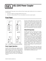
3.1 View
Figure 1: View
Table 4: Legend for Figure “View”
Pos.
Description
Details See Section
1
Marking possibility with Mini-
WSB
---
2
Status LEDs
“Device Description” > “Display Elements”
3
Data contacts
“Device Description” > “Connectors”
4
CAGE CLAMP
®
connectors
“Device Description” > “Connectors”
5
Power jumper contacts
“Device Description” > “Connectors”
6
Release tab
“Mounting” > “Inserting and Removing
Devices”

18 Device Description WAGO-I/O-SYSTEM 750 XTR
750-486/040-000 4AI 0/4-20mA NE43 Ex i XTR
Manual
Version 1.0.0
3.2 Connectors
3.2.1 Data Contacts/Local Bus
Communication between the fieldbus coupler/controller and the I/O modules as
well as the system supply of the I/O modules is carried out via the local bus. It is
comprised of 6 data contacts, which are available as self-cleaning gold spring
contacts.
Figure 2: Data Contacts
Do not place the I/O modules on the gold spring contacts!
Do not place the I/O modules on the gold spring contacts in order to avoid soiling
or scratching!
Ensure that the environment is well grounded!
The devices are equipped with electronic components that may be destroyed by
electrostatic discharge. When handling the devices, ensure that the environment
(persons, workplace and packing) is well grounded. Avoid touching conductive
components, e.g. data contacts.

WAGO-I/O-SYSTEM 750 XTR Device Description 19
750-486/040-000 4AI 0/4-20mA NE43 Ex i XTR
Manual
Version 1.0.0
3.2.2 Power Jumper Contacts/Field Supply
Risk of injury due to sharp-edged blade contacts!
The blade contacts are sharp-edged. Handle the I/O module carefully to prevent
injury.
The I/O module 750-486/040-000 has 2 self-cleaning power jumper contacts that
supply and transmit power for the field side. The contacts on the left side of the
I/O module are designed as blade contacts and those on the right side as spring
contacts.
Figure 3: Power Jumper Contacts
Table 5: Legend for Figure “Power Jumper Contacts”
Contact
Type
Function
1
Spring contact
Potential transmission (U
v
) for field supply
2
Spring contact
Potential transmission (0 V) for field supply
3
Blade contact
Potential feed-in (0 V) for field supply
4
Blade contact
Potential feed-in (U
v
) for field supply
Do not exceed maximum current via power contacts!
The maximum current available from the “Power Supply 24 VDC Diagn for Ex i
XTR Modules” 750-606/040-000 is 1 A. Greater currents can damage the power
contacts. When configuring the system, ensure that this current is not exceeded.
If exceeded, an additional 750-606/040-000 must be used.

20 Device Description WAGO-I/O-SYSTEM 750 XTR
750-486/040-000 4AI 0/4-20mA NE43 Ex i XTR
Manual
Version 1.0.0
3.2.3 CAGE CLAMP
®
Connectors
Figure 4: CAGE CLAMP
®
Connectors
Table 6: Legend for Figure “CAGE CLAMP
®
Connectors“
Channel
Designation
Connector
Function
1
U
V
1
1
Input AI 1: Sensor supply U
V
0 V
2
Input AI 1: Sensor supply 0 V
AI 1
3
Input AI 1: Signal voltage
S
4
Input AI 1: Shield connection
2
U
V
2
5
Input AI 2: Sensor supply U
V
0 V
6
Input AI 2: Sensor supply 0 V
AI 2
7
Input AI 2: Signal voltage
S
8
Input AI 2: Shield connection
3
U
V
3
9
Input AI 3: Sensor supply U
V
0 V
10
Input AI 3: Sensor supply 0 V
AI 3
11
Input AI 3: Signal voltage
S
12
Input AI 3: Shield connection
4
U
V
4
13
Input AI 4: Sensor supply U
V
0 V
14
Input AI 4: Sensor supply 0 V
AI 4
15
Input AI 4: Signal voltage
S
16
Input AI 4: Shield connection
Use shielded signal lines!
Only use shielded signal lines for analog signals and I/O modules which are
equipped with shield clamps. Only then can you ensure that the accuracy and
interference immunity specified for the respective I/O module can be achieved
even in the presence of interference acting on the signal cable.
/