Overview:
These Altronix Rack Mount CCTV Power Supplies provide 6-15VDC distributed via sixteen (16) fuse or PTC protected
outputs for powering CCTV Cameras, heaters and other video accessories.
Sixteen (16) Output Rack Mount Configuration Reference Chart:
R615DC416 4 amp 6-15VDC 16 - x 3.5 amp .9 amp
R615DC416CB 4 amp 6-15VDC 16 x - 2.5 amp .9 amp
R615DC616 6 amp 6-15VDC 16 - x 3.5 amp 1.5 amp
R615DC616CB 6 amp 6-15VDC 16 x - 2.5 amp 1.5 amp
R615DC1016 10 amp 6-15VDC 16 - x 3.5 amp 1.9 amp
R615DC1016CB 10 amp 6-15VDC 16 x - 2.5 amp 1.9 amp
Specifications:
• 2U rack mount chassis for use in standard EIA 19” rack. • Filtered and electronically regulated outputs.
• Removable terminal blocks with locking screw flange. • Short circuit and thermal overload protection.
• Power switch with built-in circuit breaker. • Unit maintains camera synchronization.
• Sixteen (16) individual power LED indicators. • Ease of installation saves time and eliminates costly labor.
Rack Dimensions:
3.25”H x 19.125”W x 8.5”D
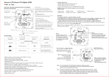
Installation Instructions:
1. Unit is factory set at 12VDC. To adjust the output voltage remove the bottom cover to access trimpot on the
power supply board
(Fig. 1B, pg. 3).
2. Mount unit in desired rack location (Space unit at least 3” from any video monitors).
3. Set power switch on back of unit to the OFF position
(Fig. 1E, pg. 3).
4. Plug power cord into grounded 115VAC 50/60 Hz receptacle (Fig. 1D, pg. 3).
5. Set power switch to the ON (RESET) position and measure output voltage before connecting devices
(
Fig. 1E, pg. 3). This helps avoid potential damage.
6. Set power switch on back of unit to the OFF position
(Fig. 1E, pg. 3).
7. Connect devices to removable terminal blocks marked [1P & 1N through 16P & 16N] (Fig. 1C, pg. 3).
When wiring is completed on ter
minal b
locks the
y can be lock
ed do
wn by tightening screw flanges.
All terminals with common suffix (P) “1P, 2P...” are the same polarity (positive).
All terminals with common suffix (N) “1N, 2N...” are the same polarity (negative).
8.
Upon completion of wiring, set power switch on back of unit to the ON (RESET) position
(F
ig. 1E, pg. 3)
.
9.
Green po
w
er LEDs on faceplate will illuminate when AC power is present. When an output is in a trouble condition
(blown fuse or tripped PTC) the corresponding LED will not be illuminated
(Fig. 1, pg. 3).
a. Blown fuse (R615DC416) - Set power switch on back of unit to the OFF position (
Fig. 1E, pg. 3).
Remove front faceplate to access fuses. Replace with fuses rated @ 3.5A/250VA (Altronix model # Fuse1).
b. Tripped PTC (R615DC416CB) - To reset PTC, set power switch on back of unit to the OFF position.
After appro
ximatel
y 30 secs. set po
w
er switch to the ON (RESET) position (
F
ig
. 1E, pg
. 3)
.
10. Power switch with b
uilt-in circuit breaker:
OFF position - Switch not Illuminated. Outputs not powered.
RESET (ON) position - Switch illuminated. Outputs powered.
Circuit breaker tripped - Switch not Illuminated. P
ower LEDs on faceplate are not illuminated. Outputs not powered.
To reset circuit breaker set power switch to the ON (RESET) position (
Fig. 1E, pg. 3).
- 2 -
Altronix
Model Number
Output Current
(max per output)
Total Output Current
(Power)
Output Voltage
115VAC
50/60Hz Input
Current
PTC Protected
Outputs
Fuse Protected
Outputs
Number of
Ouputs