Page is loading ...

PROFINET IO User Guide

TrademarkNotices
Comtrol,NS-Link,andDeviceMasterIndustrialGatewayaretrademarksofComtrolCorporation.
MicrosoftandWindowsareregisteredtrademarksofMicrosoftCorporation.
HyperTerminalisaregisteredtrademarkofHilgraeve,Inc.
PortionsofSocketServerarecopyrightedbyGoAheadSoftware,Inc.Copyright©2001.GoAheadSoftware,Inc.All
RightsReserved.
Otherproductnamesmentionedhereinmaybetrademarksand/orregisteredtrademarksoftheirrespectiveowners.
FirstEdition,August11,2017
Copyright©2017.ComtrolCorporation.
AllRightsReserved.
ComtrolCorporationmakesnorepresentationsorwarrantieswithregardtothecontentsofthisdocumentortothe
suitabilityoftheComtrolproductforanyparticularpurpose.Specificationssubjecttochangewithoutnotice.Some
softwareorfeaturesmaynotbeavailableatthetimeofpublication.Contactyourresellerforcurrentproduct
information.
Document Number: 2000639 Rev. A
Previous version: 2000484 Rev. E

DeviceMaster PNIO | UP User Guide: 2000639 Rev. A Table of Contents - 3
Table of Contents
Introduction............................................................................................................................ 7
Supported Models ..........................................................................................................................................7
Installation Overview ...................................................................................................................................7
Software and Documentation .....................................................................................................................8
Hardware Installation .......................................................................................................... 9
Product Name Change Notification ..........................................................................................................9
Installation Overview ...................................................................................................................................9
1-Port - Panel Mount (DB9) Installation.................................................................................................10
PNIO-2201: 1-Port DIN Rail (Terminal Block) Installation................................................................12
PNIO-2101: 1-Port DIN Rail (DB9) Installation.....................................................................................13
PNIO-2202 and PNIO-2402: 2-Port DIN Rail (Terminal Block) Installation...................................15
PNIO-2102 and PNIO-2302: 2-Port DIN Rail (DB9) Installation........................................................17
PNIO-2304: 4-Port DIN Rail (DB9) Installation.....................................................................................19
4-Port Panel Mount Installation...............................................................................................................20
Adding a Unit to an Existing Installation ..............................................................................................21
Replacing Hardware ...................................................................................................................................22
Preparing the DeviceMaster for Configuration ........................................................... 23
PortVision DX Overview ............................................................................................................................23
PortVision DX Requirements....................................................................................................................24
Installing PortVision DX ............................................................................................................................24
Configuring the Network Settings...........................................................................................................27
Checking the Protocol Firmware Version .............................................................................................30
Uploading Protocol-Specific Firmware on the DeviceMaster ..........................................................31
Customizing PortVision DX.......................................................................................................................33
Accessing DeviceMaster Documentation from PortVision DX .........................................................34
How to Download Documentation............................................................................................................ 34
How to Open Previously Downloaded Documents .................................................................................. 35
Connecting Serial Devices................................................................................................. 37
DB9 Connectors............................................................................................................................................38
DB9 Null-Modem Cables (RS-232)...........................................................................................................39
DB9 Null-Modem Cables (RS-422)...........................................................................................................39
DB9 Straight-Through Cables (RS-232/485) ...........................................................................................39
DB9 Loopback Plugs ................................................................................................................................. 40
Connecting DB9 Serial Devices................................................................................................................ 40
RJ45 Connectors ..........................................................................................................................................41
RJ45 Null-Modem Cables (RS-232) ......................................................................................................... 41
RJ45 Null-Modem Cables (RS-422) ......................................................................................................... 42
RJ45 Straight-Through Cables (RS-232/485) ..........................................................................................42
RJ45 Loopback Plugs................................................................................................................................ 42
RJ45 RS-485 Test Cable ........................................................................................................................... 42
Connecting RJ45 Devices ......................................................................................................................... 43

4 - Table of Contents DeviceMaster PNIO | UP User Guide: 2000639 Rev. A
Table of Contents
Four Screw Terminals ................................................................................................................................44
Serial Terminal (4) Connectors ................................................................................................................ 44
Serial Terminal (4) Null-Modem Cables (RS-232) ..................................................................................45
Serial Terminal (4) Null-Modem Cables (RS-422) ..................................................................................45
Serial Terminal (4) Straight-Through Cables (RS-232/485)................................................................... 45
Serial Terminal (4) Loopback Signals...................................................................................................... 46
Connecting Serial Devices ........................................................................................................................ 46
Eight Screw Terminals ...............................................................................................................................47
Screw Terminal (8) Connectors ................................................................................................................ 47
Screw Terminal (8) Null-Modem Cables (RS-232) .................................................................................. 48
Screw Terminal (8) Null-Modem Cables (RS-422) .................................................................................. 48
Screw Terminal (8) Straight-Through Cables (RS-232/485) .................................................................. 48
Screw Terminal (8) Loopback Signals ..................................................................................................... 49
Connecting Serial Devices ........................................................................................................................ 49
Nine Screw Terminals ................................................................................................................................50
Screw Terminal Connectors (9) ................................................................................................................ 50
Screw Terminal (9) Null-Modem RS-232 Cables .................................................................................... 50
Screw Terminal (9) Null-Modem RS-422 Cables .................................................................................... 51
Screw Terminal (9) RS-232/485 Straight-Through Cables ..................................................................... 51
Screw Terminal (9) Loopback Signals ..................................................................................................... 51
Connecting Serial Devices ........................................................................................................................ 52
Configuring a Serial Port .................................................................................................. 53
Configuring an Ethernet Device...................................................................................... 61
Configuring the DeviceMaster in TIA Portal................................................................ 69
Installing the GSD File ...............................................................................................................................69
Adding the DeviceMaster...........................................................................................................................69
IP Address Assignment...............................................................................................................................70
Assigning an IP Address Statically.......................................................................................................... 71
Assigning IP Address Statically Using the Web Page...................................................................... 71
Assigning IP Address Statically Using TIA Portal........................................................................... 72
Configuring TIA Portal Project Not to Set IP Address..................................................................... 73
Assigning an IP Address via DHCP......................................................................................................... 73
Assigning an IP Address via IO Controller ............................................................................................. 74
Special Considerations Regarding IP Assignment..................................................................................75
Device Name Assignment...........................................................................................................................75
Assigning the Device Name Using the Web Interface ............................................................................ 75
Assigning the Device Name in TIA Portal............................................................................................... 76
Configuring Device Name in TIA Portal Project..................................................................................... 77
Establishing A PROFINET IO Connection ............................................................................................78
Status LED Behavior...................................................................................................................................79
Configuring IO Modules .............................................................................................................................79
Inserting IO Modules and Submodules ................................................................................................... 79
Input and Output Submodule Data Format............................................................................................ 81

DeviceMaster PNIO | UP User Guide: 2000639 Rev. A Table of Contents - 5
Table of Contents
IO Data Handling................................................................................................................. 83
Input Data Handling ...................................................................................................................................83
Handling Input Data in PLC.................................................................................................................... 85
Setting the IO Cycle Update Time ...........................................................................................................85
Output Data Handling ................................................................................................................................86
Formatting an Output Packet.................................................................................................................. 86
Transmitting an Output Packet............................................................................................................... 86
Appending Delimiters...............................................................................................................................87
Project Example................................................................................................................... 89
Reading Input Data .....................................................................................................................................89
Writing Output Data ...................................................................................................................................92
Advanced Functions ........................................................................................................... 95
Handling Oversize Packets........................................................................................................................95
Sample PLC Program Handling Oversize Packets ................................................................................. 97
Enable Alarm for Oversize Packets ......................................................................................................... 98
Shared Device Functionality ....................................................................................................................99
Network Menu .................................................................................................................... 103
Configuration Page ...................................................................................................................................103
Password Page............................................................................................................................................105
Security Page ..............................................................................................................................................106
Keys/Certs Page..........................................................................................................................................107
Client Authentication ............................................................................................................................. 108
Changing Keys and Certificates............................................................................................................. 109
PROFINET IO Page ..................................................................................................................................109
Diagnostics Menu .............................................................................................................. 111
Communication Statistics Page .............................................................................................................112
Serial Log.....................................................................................................................................................116
Ethernet Log ...............................................................................................................................................117
System Log...................................................................................................................................................118
System Info..................................................................................................................................................119
System Menu....................................................................................................................... 121
Update Firmware.......................................................................................................................................121
Configuration File .....................................................................................................................................124
Saving a Configuration File ................................................................................................................... 124
Loading a Configuration File ................................................................................................................. 125
Device Snapshot .........................................................................................................................................125
Restore Defaults.........................................................................................................................................126
Reboot...........................................................................................................................................................126

6 - Table of Contents DeviceMaster PNIO | UP User Guide: 2000639 Rev. A
Table of Contents
Managing the DeviceMaster ........................................................................................... 127
Rebooting the DeviceMaster ...................................................................................................................127
Uploading Firmware to Multiple DeviceMasters...............................................................................128
Configuring Multiple DeviceMasters Network Addresses...............................................................129
Adding a New Device in PortVision DX................................................................................................129
Remote Using the IP Address ................................................................................................................ 129
Local Using the IP Address or MAC Address........................................................................................ 130
Changing the Bootloader Timeout ........................................................................................................131
Managing Bootloader................................................................................................................................132
Checking the Bootloader Version........................................................................................................... 132
Uploading Bootloader ............................................................................................................................. 132
Restoring Factory Defaults (Specific Models) ....................................................................................134
Accessing RedBoot Commands in Telnet/SSH Sessions (PortVision DX) ....................................135
RedBoot Procedures ......................................................................................................... 139
Accessing RedBoot Overview .................................................................................................................139
Establishing a Serial Connection...........................................................................................................140
Establishing a Telnet Connection..........................................................................................................141
Determining the Network Settings .......................................................................................................142
Configuring the Network Settings.........................................................................................................142
Changing the Bootloader Timeout ........................................................................................................143
Determining the Bootloader Version....................................................................................................143
Resetting the DeviceMaster ....................................................................................................................144
Configuring Passwords ............................................................................................................................144
RedBoot Command Overview.................................................................................................................145
External Power Supply Specifications......................................................................... 149
1-Port Panel Mount 5-30VDC Power Supply .......................................................................................149
PNIO-2101 and PNIO-2201: 1-Port DIN Rail Power Supply .............................................................150
PNIO-2202 and PNIO-2402: 2-Port (Serial Terminals) Power Supply ...........................................151
PNIO-2102 and PNIO-2302: 2-Port DB9 Power Supply (Bottom) ....................................................152
PNIO-2102 and PNIO-2302: 2-Port DB9 Power Supply (Top)...........................................................153
PNIO-2304: 4-Port DIN Rail Models Power Supply............................................................................154
4-Port Panel Mount Power Supply ........................................................................................................154
Troubleshooting and Technical Support..................................................................... 155
Troubleshooting Checklist .....................................................................................................................155
General Troubleshooting .........................................................................................................................157
Daisy-Chaining DeviceMaster 4-Port Units.........................................................................................158
DeviceMaster LEDs ...................................................................................................................................159
TX/RX LEDs ............................................................................................................................................ 159
Network and Device LEDs ..................................................................................................................... 159
Technical Support .....................................................................................................................................160

DeviceMaster PNIO | UP User Guide: 2000639 Rev. A Introduction - 7
Introduction
Supported Models
This User Guide supports the DeviceMaster Industrial Gateway, which includes
the following products:
• DeviceMaster UP 1-port panel mount
• DeviceMaster PNIO-2101and DeviceMaster PNIO-2201: 1-port DIN rail
models
• DeviceMaster UP all 2-port DIN rail models: DeviceMaster PNIO-2xx2 series
Note: DeviceMaster UP 2-port models have been renamed.
• DeviceMaster PNIO-2304: 4-port DIN rail
• DeviceMaster UP 4-port panel mount
Note: DeviceMaster Industrial Gateway products (DeviceMaster UP and PNIO-
2000 series) are typically referred to as DeviceMaster in this User Guide.
Installation Overview
This User Guide is organized to reflect the installation step order:
1. Install the hardware (Page 9).
2. Configure the IP address (Page 27).
3. If necessary, upload the latest firmware (Page 30).
4. Attach the serial device (Page 37).
5. Configure the serial port or ports (Page 53).
6. Configure the Ethernet device (Page 61).
7. Configure the DeviceMaster in TIA Portal (Page 69).
In addition, this User Guide also provides the following information:
• IO data handling (Page 83)
• Provides an example project (Page 89)
• Advanced functions (Page 95)
• Provides information about the DeviceMaster PNIO application web pages
(
Page 103)
• DeviceMaster Diagnostics web pages (Page 111)
• DeviceMaster maintenance and Redboot procedures (Page 127)
Old Product Name
New Model
Name
DeviceMaster UP 2-Port with 1 Ethernet port PNIO-2202
DeviceMaster UP 2-Port with 2 Ethernet port PNIO-2402
DeviceMaster UP 2-Port DB9 with 1 Ethernet port PNIO-2102
DeviceMaster UP 2-Port DB9 with 2 Ethernet ports PNIO-2302

8 - Introduction DeviceMaster PNIO | UP User Guide: 2000639 Rev. A
Introduction
Software and Documentation
You can access the appropriate firmware assembly, PortVision DX, and the
DeviceMaster documentation from the download site using the links in the
following tables.
DeviceMaster UP Software and Firmware Link
Bootloader
Bootloader, the operating system that runs on the DeviceMaster
hardware during the power on phase, which then starts the
default application, PROFINET IO.
PortVision DX
PortVision DX is the application for Windows that you use to
configure network settings and update the firmware.
Use PortVision DX to manage Comtrol Ethernet-attached
devices to:
• Scan the network for attached devices
• View networked devices in real-time
• Access product-specific network settings configurations
• Assign IP addresses and network settings to one or multiple
devices
• Upload the latest firmware or Bootloader
• Save and load configuration files
• Access DeviceMaster configuration web pages
• Access Telnet/SSH sessions
• Remotely reboot devices
• Download technical documentation
• Enable event logging to assist in monitoring and
troubleshooting
• Create shortcuts to quickly access your favorite applications
• Organize devices into folders and create multiple views
• Enter notes about a folder or device
PROFINET IO Firmware and Documentation Link
Firmware
PROFINET IO (.msi) contains the firmware and supporting
files. The firmware provides embedded configuration web
pages. You may need to update the DeviceMaster with the
latest version.
Depending on the model you purchased, the DeviceMaster
may or may not have the PROFINET IO firmware loaded.
Note: Models that have a protocol loaded on the
DeviceMasterare identified in PortVision DX and the
DeviceMaster is labeled accordingly.
Documentation This User Guide.

DeviceMaster PNIO | UP User Guide: 2000639 Rev. A Hardware Installation - 9
Hardware Installation
Product Name Change Notification
Comtrol has implemented a product name change for our DeviceMaster and
DeviceMaster UP 2-port DIN rail models to align with our new 1-port and 4-port
DIN rail model names.
Note: The DeviceMaster UP 2-port DIN rail PROFINET IO models also have new
part numbers.
Installation Overview
Use the links below to locate installation procedures for the following models:
Old Name/
Description
New Model
Name
Old Part
Number
New Part
Number
DeviceMaster UP
2-Port 1E
PROFINET IO
DeviceMaster
PNIO-2202
99531-9 99534-0
DeviceMaster UP
2-Port DB9 1E
PROFINET IO
DeviceMaster
PNIO-2102
99551-7 99628-6
DeviceMaster UP
2-Port 2E
PROFINET IO
DeviceMaster
PNIO-2402
99541-8 99544-9
DeviceMaster UP
2-Port DB9 2E
PROFINET IO
DeviceMaster
PNIO-2302
99561-6 99633-0
Ports
DeviceMaster or
DeviceMaster UP Model
Installation Procedure
1
DeviceMaster UP
DB9 serial port
Panel mount
1-Port - Panel Mount (DB9) Installation
on Page 10
1
DeviceMaster PNIO-2201
Screw terminal serial port
DIN rail
PNIO-2201: 1-Port DIN Rail (Terminal
Block) Installation on Page 12
1
DeviceMaster PNIO-2101
DB9 serial port
DIN rail
PNIO-2101: 1-Port DIN Rail (DB9)
Installation on Page 13
2
DeviceMaster PNIO-2202
DeviceMaster PNIO-2402
Screw terminal serial ports
DIN rail
PNIO-2202 and PNIO-2402: 2-Port DIN
Rail (Terminal Block) Installation on
Page 15
2
DeviceMaster PNIO-2102
DeviceMaster PNIO-2302
DB9 serial ports
DIN rail
PNIO-2102 and PNIO-2302:
2-Port DIN
Rail (DB9) Installation on Page 17

10 - Hardware Installation DeviceMaster PNIO | UP User Guide: 2000639 Rev. A
Hardware Installation
1-Port - Panel Mount (DB9) Installation
Use the following procedure to install the DeviceMaster 1-Port (panel mount).
1. Place the DeviceMaster 1-Port on a stable surface and skip to Step 2 or
optionally mount the DeviceMaster using the mounting flanges or DIN rail
adapters.
a. Pick up the DeviceMaster so that the front of the device is facing you.
b. Pick up a DIN rail clip. (The three tines should be on top
and the M4 label should face you.)
c. Slide the DIN rail clip behind the DeviceMaster and line
it up with one of the screw holes on the DeviceMaster.
d. Insert the M4 screw into the hole and tighten with a
Phillips screwdriver.
e. Repeat Steps b through d with the second DIN rail clip.
Make sure the screws on both DIN rail clips line up.
Note: If you need to remove the DeviceMaster from the
DIN rail, exert pressure on the backside of the
tabs at the bottom of both DIN rail clips.
f. Attach the DeviceMaster to the DIN rail.
Note: Do not connect multiple units until you have changed the default IP
address, see Preparing the DeviceMaster for Configuration on Page 23
2. Connect the DeviceMaster port labeled 10/100 ETHERNET to the same
Ethernet network segment as the PLC using a standard network cable.
3. Apply power to the DeviceMaster using the following procedure.
Note: See 1-Port Panel Mount 5-30VDC Power Supply on Page 149, if you
want to provide your own power supply.
4
DeviceMaster PNIO-2304
DB9 serial ports
DIN rail
PNIO-2304: 4-Port DIN Rail (DB9)
Installation on Page 19
4
DeviceMaster UP D
B9 serial ports
Panel mount
4-Port Panel Mount Installation
on Page
20
Ports
DeviceMaster or
DeviceMaster UP Model
Installation Procedure
M4
DIN Rail
Clip
Side
Press here
Front View
DeviceMaster

DeviceMaster PNIO | UP User Guide: 2000639 Rev. A Hardware Installation - 11
Hardware Installation
Observe proper ESD techniques when connecting and disconnecting
the DeviceMaster.
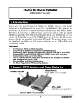
• Insert the earth ground wire into the earth ground screw terminal.
• Insert the DC positive wire into the
positive screw terminal and the DC
return wire into the return screw
terminal.
Refer to 1-Port Panel Mount 5-30VDC
Power Supply on Page 149 for detailed
power requirements.
• Use a small flat head screw to lock the
wires into place.
• Verify that each wire has been tightened
securely.
• Plug the screw terminal power
connector into the DeviceMaster.
Note: Align the plug properly. The scalloped side of
the screw terminal power connector should be
aligned with the scalloped side of the power
jack on the unit.
• Connect the power supply to a power source.
•Go to Step 4 to verify that the DeviceMaster is
functioning properly.
4. Verify that the Status LED has completed the boot cycle
and network connection for the DeviceMaster is functioning properly using the
table below.
Do not connect RS-422/485 devices until the IP address is configured
and an appropriate port interface type has been configured. The
default port setting is RS-232.
5. Go to Preparing the DeviceMaster for Configuration on Page 23 to install
PortVision DX, configure the network settings, and if necessary, upload the
appropriate protocol firmware on the DeviceMaster.
1-Port Enclosed LED Descriptions
Status
The amber Status LED on the device is lit, indicating you have power
and it has completed the boot cycle.
Note: The Status LED flashes while booting and it takes
approximately 15 seconds for the Bootloader to complete the
cycle. When the Bootloader completes the cycle, the LED
flashes rapidly for several times then stays off and blinks
approximately every 10 seconds when there is no PLC
connection.
Link/Act
If the red Link/Act LED is lit, it indicates a working Ethernet
connection.
Duplex If the red Duplex LED is lit, it indicates full-duplex activity.
100
If the red 100 LED is lit, it indicates a working 100 MB Ethernet
connection (100 MB network, only). If the LED is not lit, it indicates
a 10 MB Ethernet connection.
Note: For additional LED information, go to the Status LED table on Page 156.
Caution
Earth Gnd
Return
Positive
5-30VDC
+
-
Wire gauge:
AWG 12-22
Caution

12 - Hardware Installation DeviceMaster PNIO | UP User Guide: 2000639 Rev. A
Hardware Installation
PNIO-2201: 1-Port DIN Rail (Terminal Block) Installation
Use the following procedure to install PNIO-2201. See PNIO-2101: 1-Port DIN
Rail (DB9) Installation on Page 13 if the DeviceMaster has DB9 serial connectors.
1. Attach the PNIO-2201 1-Port to the DIN rail adapter.
2. Connect the power supply and apply power to the PNIO-2201 using the power
supply specifications on the product label and the following information.
Observe proper ESD techniques when connecting and disconnecting
the DeviceMaster.
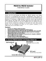
a. If the DIN rail is not connected to earth ground, insert the earth ground
wire into the chassis ground screw terminal.
Note: The chassis ground
connection is made
only if the DIN rail is
NOT connected to
earth ground.
b. Insert the DC positive
wire into the + screw
terminal and the DC
return wire into the -
screw terminal.
Refer to PNIO-2101 and
PNIO-2201: 1-Port DIN
Rail Power Supply on
Page 150 for detailed
power requirements.
c. Use a small flat head
screw driver to lock the wires into place.
d. Verify that each wire has been tightened securely.
e. Connect a UL Listed power supply and UL Listed power cord to a power
source to apply power.
Note: Do not connect multiple units until you have changed the default IP
address, see
Preparing the DeviceMaster for Configuration on Page 23
3. Connect the 10/100 port to the same Ethernet network segment as the host PC
using a standard network cable.
4. Verify that the Status LED has completed the boot cycle and network
connection for the PNIO-2201 is functioning using the following table.
Caution
PNIO-2201 LED Descriptions
STATUS
The STATUS LED on the device is lit, indicating you have power and it
has completed the boot cycle.
Note: The Status LED flashes while booting and it takes approximately
15 seconds for the Bootloader to complete the cycle. When the
Bootloader completes the cycle, the LED flashes rapidly for
several times then stays off and blinks approximately every 10
seconds when there is no PLC connection.
LINK
If the LINK (green) LED is lit, it indicates a working Ethernet
connection.
ACT If the ACT (yellow) LED flashes, it indicates network activity.
Note: For additional LED information, go to the Status LED table on Page 156.
† Wire gauge: AWG 12-22
PW1
PW2
Chassis
Ground†
Return†
Positive†Positive†
5-30VDC 5-30VDC

DeviceMaster PNIO | UP User Guide: 2000639 Rev. A Hardware Installation - 13
Hardware Installation
Do not connect RS-422/485 devices until the IP address is configured
and an appropriate port interface type has been configured. The
default port setting is RS-232.
5. Go to Preparing the DeviceMaster for Configuration on Page 23 for default
network settings and how to configure the DeviceMaster for use.
PNIO-2101: 1-Port DIN Rail (DB9) Installation
Use the following procedure to install a PNIO-2101.
1. Attach the PNIO-2101 to the DIN rail adapter.
2. Connect the power supply and apply power to the PNIO-2101 using the power
supply specifications on the product label and the following information.
Observe proper ESD techniques when connecting and disconnecting
the DeviceMaster.
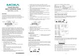
a. If the DIN rail is not
connected to earth
ground, insert the earth
ground wire into the
chassis ground screw
terminal.
Note: The chassis
ground
connection is
made only if the
DIN rail is NOT
connected to
earth ground.
b. Insert the DC positive
wire into one of the +
screw terminals and the
DC return wire into the
- screw terminal.
• A second redundant power supply can be connected to the unit by
inserting the DC positive wire into the other + screw terminal and the
DC return wire into the - screw terminal.
• The PNIO-2101 continues to operate if one of the two connected power
supplies should fail.
Refer to PNIO-2101 and PNIO-2201: 1-Port DIN Rail Power Supply on
Page 150 for detailed power requirements.
c. Use a small flat head screw driver to lock the wires into place.
d. Verify that each wire has been tightened securely.
e. Connect a UL Listed power supply and UL Listed power cord to a power
source to apply power.
Note: Do not connect multiple units until you have changed the default IP
address, see
Preparing the DeviceMaster for Configuration on Page 23
3. Connect the 10/100 port to the same Ethernet network segment as the host PC
using a standard Ethernet cable.
Caution
Caution
† Wire gauge: AWG 12-22
PW1
PW2
Chassis
Ground†
Return†
Positive†Positive†
5-30VDC 5-30VDC

14 - Hardware Installation DeviceMaster PNIO | UP User Guide: 2000639 Rev. A
Hardware Installation
4. Verify that the Status LED has completed the boot cycle and network
connection for the PNIO-2101 is functioning properly using the following
table.
Do not connect RS-422/485 devices until the IP address is configured
and an appropriate port interface type has been configured. The
default port setting is RS-232.
5. Go to Preparing the DeviceMaster for Configuration on Page 23 for default
network settings and how to configure the DeviceMaster for use.
PNIO-2101 LED Descriptions
STATUS
The STATUS LED on the device is lit, indicating you have power and
it has completed the boot cycle.
Note: The Status LED flashes while booting and it takes
approximately 15 seconds for the Bootloader to complete the
cycle. When the Bootloader completes the cycle, the LED
flashes rapidly for several times then stays off and blinks
approximately every 10 seconds when there is no PLC
connection.
LINK
If the LINK (green) LED is lit, it indicates a working Ethernet
connection.
ACT If the ACT (yellow) LED flashes, it indicates network activity.
Note: For additional LED information, go to the Status LED table on Page 156.
Caution

DeviceMaster PNIO | UP User Guide: 2000639 Rev. A Hardware Installation - 15
Hardware Installation
PNIO-2202 and PNIO-2402: 2-Port DIN Rail (Terminal Block) Installation
Use the following procedure to install DeviceMaster 2-port models (1E and 2E)
with serial screw terminal connectors. See
PNIO-2102 and PNIO-2302: 2-Port
DIN Rail (DB9) Installation on Page 17 if the DeviceMaster has DB9 serial
connectors.
1. Attach the DeviceMaster 2-Port to the DIN rail adapter.
2. Connect the power supply and apply power to the DeviceMaster using the
power supply specifications on the product label and the following
information.
Observe proper ESD techniques when connecting and disconnecting
the DeviceMaster.
a. If the DIN rail is not connected to earth ground, insert the earth ground
wire into the chassis ground screw terminal.
Note: The chassis ground
connection is made
only if the DIN rail
is NOT connected to
earth ground.
b. Insert the DC positive
wire into the + screw
terminal and the DC
return wire into the -
screw terminal.
Refer to PNIO-2202
and PNIO-2402: 2-Port
(Serial Terminals)
Power Supply on Page
151 for power
requirements.
c. Use a small flat head
screw driver to lock the
wires into place.
d. Verify that each wire has been tightened securely.
e. Connect a UL Listed power supply and UL Listed power cord to a power
source to apply power.
Note: Do not connect multiple units until you have changed the default IP
address, see
Preparing the DeviceMaster for Configuration on Page 23
3. Use the appropriate method for network attachment of the DeviceMaster.
• PNIO-2202: Connect the 10/100 port to the same Ethernet network
segment as the host PC using a standard network cable.
• PNIO-2402: Connect the DeviceMaster using either Ethernet port to the
same Ethernet network segment as the host PC using a standard Ethernet
cable. You can daisy-chain another DeviceMaster or Ethernet device to the
other Ethernet port.
Note: If your model provides two Ethernet ports, E1 is the first port and E2 is
the second port.
Caution
Signal
Ground†
Chassis
Ground†
Positive†
Return†
6-30VDC
† Wire gauge: AWG 12-22
Signal Ground is used to connect RS-232 devices
later in the installation.

16 - Hardware Installation DeviceMaster PNIO | UP User Guide: 2000639 Rev. A
Hardware Installation
4. Verify that the Status LED has completed the boot cycle and network
connection for the DeviceMaster is functioning properly using the following
table.
Do not connect RS-422/485 devices until the IP address is configured
and an appropriate port interface type has been configured. The
default port setting is RS-232.
5. Go to Preparing the DeviceMaster for Configuration on Page 23 for default
network settings and how to configure the DeviceMaster for use.
2-Port with Serial Terminal Connectors LED Descriptions
STATUS
The STATUS LED on the device is lit, indicating you have power and
it has completed the boot cycle.
Note: The Status LED flashes while booting and it takes
approximately 15 seconds for the Bootloader to complete the
cycle. When the Bootloader completes the cycle, the LED
flashes rapidly for several times then stays off and blinks
approximately every 10 seconds when there is no PLC
connection.
LINK
If the LINK (green) LED is lit, it indicates a working Ethernet
connection.
ACT If the ACT (yellow) LED flashes, it indicates network activity.
Note: For additional LED information, go to the Status LED table on Page 156.
Caution

DeviceMaster PNIO | UP User Guide: 2000639 Rev. A Hardware Installation - 17
Hardware Installation
PNIO-2102 and PNIO-2302: 2-Port DIN Rail (DB9) Installation
Use the following procedure to install DeviceMaster 2-port models (1E and 2E)
with DB9 connectors.
1. Attach the DeviceMaster 2-Port to the DIN rail adapter.
2. Connect the power supply and apply power to the DeviceMaster using the
power supply specifications on the product label and the following
information.
Observe proper ESD techniques when connecting and disconnecting
the DeviceMaster.
a. If the DIN rail is not connected to earth ground, insert the earth ground
wire into the chassis ground screw terminal.
Note: The chassis ground connection is made only if the DIN rail is NOT
connected to earth ground.
b. Insert the DC positive wire into one of the + screw terminals and the DC
return wire into the - screw terminal.
Type 1: 6-30VDC - serial number less than xxxx-030000.
Type 2: 5-30VDC - serial number greater than xxxx-030000.
A second redundant power supply can be connected to the unit by inserting
the DC positive wire into the other + screw terminal and the DC return
wire into the - screw terminal. The DeviceMaster continues to operate if one
of the two connected power supplies should fail.
Refer to the appropriate subsection for detailed power requirements.
• PNIO-2102 and PNIO-2302: 2-Port DB9 Power Supply (Bottom) on
Page 152
• PNIO-2102 and PNIO-2302: 2-Port DB9 Power Supply (Top) on Page
153
c. Use a small flat head screw driver to lock the wires into place.
d. Verify that each wire has been tightened securely.
e. Connect a UL Listed power supply and UL Listed power cord to a power
source to apply power.
Note: Do not connect multiple units until you have changed the default IP
address, see Preparing the DeviceMaster for Configuration on Page 23.
Caution
PW1 PW2
Return†
Positive†Positive†
Chassis
Ground†
† Wire gauge: AWG 12-22
Type 1 DeviceMaster:
Power Terminal - Bottom of Unit
PW1
PW2
Chassis
Ground†
Return†
Positive†Positive†
Type 2 DeviceMaster:
Power Terminal - Top of Unit
6-30VDC 6-30VDC
5-30VDC 5-30VDC

18 - Hardware Installation DeviceMaster PNIO | UP User Guide: 2000639 Rev. A
Hardware Installation
3. Use the appropriate method for network attachment of your DeviceMaster 2-
port:
• PNIO-2102: Connect the 10/100 port to the same Ethernet network
segment as the host PC using a standard network cable.
• PNIO-2302: Connect either 10/100 port to the same Ethernet network
segment as the host PC using a standard network cable. You can daisy-
chain another DeviceMaster or Ethernet device to the other Ethernet port.
Note: If your model provides two Ethernet ports, E1 is the first port and E2 is
the second port.
4. Verify that the Status LED has completed the boot cycle and network
connection for the DeviceMaster is functioning using the following table.
Do not connect RS-422/485 devices until the IP address is configured
and an appropriate port interface type has been configured. The
default port setting is RS-232.
5. Go to Preparing the DeviceMaster for Configuration on Page 23 for default
network settings and how to configure the DeviceMaster for use.
2-Port with DB9 Connectors LED Descriptions
STATUS
The STATUS LED on the device is lit, indicating you have power and
it has completed the boot cycle.
Note: The Status LED flashes while booting and it takes
approximately 15 seconds for the Bootloader to complete the
cycle. When the Bootloader completes the cycle, the LED
flashes rapidly for several times then stays off and blinks
approximately every 10 seconds when there is no PLC
connection.
LINK
If the LINK (green) LED is lit, it indicates a working Ethernet
connection.
ACT If the ACT (yellow) LED flashes, it indicates network activity.
Note: For additional LED information, go to the Status LED table on Page 156.
Caution

DeviceMaster PNIO | UP User Guide: 2000639 Rev. A Hardware Installation - 19
Hardware Installation
PNIO-2304: 4-Port DIN Rail (DB9) Installation
Use the following procedure to install PNIO-2304.
1. Attach the DeviceMaster to the DIN rail adapter.
2. Connect the power supply and apply power to the DeviceMaster using the
power supply specifications on the product label and the following
information.
Observe proper ESD techniques when connecting and disconnecting
the DeviceMaster.
a. If the DIN rail is not
connected to earth
ground, insert the earth
ground wire into the
chassis ground screw
terminal.
Note: The chassis ground
connection is made
only if the DIN rail is
NOT connected to
earth ground.
b. Insert the DC positive
wire into one of the +
screw terminals and the
DC return wire into the
- screw terminal.
• A second redundant
power supply can be connected to the unit by inserting the DC positive
wire into the other + screw terminal and the DC return wire into the -
screw terminal.
• The DeviceMaster continues to operate if one of the two connected
power supplies should fail.
Refer to PNIO-2304: 4-Port DIN Rail Models Power Supply on Page 154 for
detailed power requirements.
c. Use a small flat head screw driver to lock the wires into place.
d. Verify that each wire has been tightened securely.
e. Connect a UL Listed power supply and UL Listed power cord to a power
source to apply power.
Note: Do not connect multiple units until you have changed the default IP
address, see
Preparing the DeviceMaster for Configuration on Page 23
3. Connect one of the 10/100 ports to the same Ethernet network segment as the
host PC using a standard Ethernet cable. You can daisy-chain another
DeviceMaster or Ethernet device to the other port using a standard Ethernet
cable.
Note: This model provides two Ethernet ports, E1 is the first port and E2 is
the second port.
Caution
† Wire gauge: AWG 12-22
PW1
PW2
Chassis
Ground†
Return†
Positive†Positive†
5-30VDC 5-30VDC

20 - Hardware Installation DeviceMaster PNIO | UP User Guide: 2000639 Rev. A
Hardware Installation
4. Verify that the Status LED has completed the boot cycle and network
connection for the DeviceMaster is functioning properly using the following
table.
Do not connect RS-422/485 devices until the IP address is configured
and an appropriate port interface type has been configured. The
default port setting is RS-232.
5. Go to Preparing the DeviceMaster for Configuration on Page 23 for default
network settings and how to configure the DeviceMaster for use.
4-Port Panel Mount Installation
Use the following procedure to install the DeviceMaster 4-port.
1. Optionally, attach the mounting brackets using the screws provided in the kit
(6-32 1/4” flathead machine) or place the DeviceMaster on a stable surface.
Failure to use the correct screws can damage the PCB and void the
warranty. Do NOT use screws that exceed the length of the screws
provided with the mounting bracket kit.
Note: If you ordered the DeviceMaster Rackmount Shelf Kit accessory, use the
document that accompanied that kit or download the document to
mount the DeviceMaster on the shelf.
2. Connect the DeviceMaster to the same Ethernet network segment as the PLC.
If the DeviceMaster serial number is below xxxx-030000 use one of the
following methods to connect the cable. Serial numbers above xxxx-030000,
the Ethernet port are interchangeable.
• Ethernet hub or switch (10/100Base-T): Connect to the port labeled UP
on the DeviceMaster using a standard Ethernet cable.
• Server NIC (10/100Base-T): Connect to the port labeled DOWN on the
DeviceMaster using a standard Ethernet cable.
• Daisy-chaining DeviceMaster units: Connect the port labeled DOWN on
the first DeviceMaster to the port labeled UP on the second DeviceMaster
or other device using a standard Ethernet cable. Refer to
Daisy-Chaining
DeviceMaster 4-Port Units on Page 158.
Note: Your model provides two Ethernet ports, UP is the first port and DOWN
is the second port.
Note: Do not connect multiple units until you have changed the default IP
address, see
Preparing the DeviceMaster for Configuration on Page 23
PNIO-2304 LED Descriptions
STATUS
The STATUS LED on the device is lit, indicating you have power and it
has completed the boot cycle.
Note: The Status LED flashes while booting and it takes approximately
15 seconds for the Bootloader to complete the cycle. When the
Bootloader completes the cycle, the LED flashes rapidly for
several times then stays off and blinks approximately every 10
seconds when there is no PLC connection.
LINK
If the LINK (green) LED is lit, it indicates a working Ethernet
connection.
ACT If the ACT (yellow) LED flashes, it indicates network activity.
Note: For additional LED information, go to the Status LED table on Page 156.
Caution
Caution
/