Page is loading ...

It is of vital importance, before attempting to
operate your engine, to read the general
'SAFETY INSTRUCTIONS AND WARNINGS'
section on pages 2-5 of this booklet and to strictly
adhere to the advice contained therein.
●
Also, please study the entire contents of this
instruction manual, so as to familiarize yourself
with the controls and other features of the
engine.
Keep these instructions in a safe place so that
you may readily refer to them whenever
necessary.
It is suggested that any instructions supplied
with the vehicle, radio control equipment, etc.,
are accessible for checking at the same time.
●
●

CONTENTS
SAFETY INSTRUCTIONS AND
WARNINGS ABOUT YOUR O.S. ENGINE
INTRODUCTION, BASIC ENGINE PARTS
INSTALLATION
NOTES CONCERING
THE RECOIL STARTER
GLOWPLUG
TOOLS, ACCESSORIES, etc.
CARBURETTOR CONTROLS
STARTING & INITIAL
RUNNING-IN('Breaking-in)
2
~
5
6
7
7
~
8
8
~
9
9
~
10
12
~
13
13
13
~
15
15
~
16
16
17
18
19
20
ADJUSTMENT
CARE AND MAINTENANCE
O.S. GENUINE PARTS &
ACCESSORIES
THREE VIEW DRAWING
ENGINE EXPLODED VIEW
ENGINE PARTS LIST
CARBURETTOR EXPLODED VIEW &
PARTS LIST
11
IF THE ENGINE FAILS TO START
1

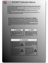
Remember that your engine is not a "toy", but a highly efficient internal-
combustion machine whose power is capable of harming you, or others, if it is
misused.
As owner, you, alone, are responsible for the safe operation of your engine, so act
with discretion and care at all times.
If at some future date, your O.S. engine is acquired by another person, we would
respectfully request that these instructions are also passed on to its new owner.
SAFETY INSTRUCTIONS AND WARNINGS ABOUT YOUR O.S. ENGINE
The advice which follows applies basically to ALL MODEL ENGINES and is
grouped under two headings according to the degree of damage or danger
which might arise through misuse or neglect.
WARNINGS
NOTES
These cover events which
might involve serious (in
extreme circumstances, even
fatal) injury.
These cover the many other
possibilities, generally less obvious
sources of danger, but which, under
certain circumstances, may also
cause damage or injury.
2

WARNINGS
Model engine fuel is poison-
ous. Do not allow it to come into
contact with the eyes or mouth.
Always store it in a clearly
marked container and out of the
reach of children.
Model engine fuel is also highly
flammable. Keep it away from
open flame, excessive heat,
sources of sparks, or anything
else which might ignite it. Do
not smoke or allow anyone else
to smoke, near to it.
Never operate your engine in an en-
closed space. Model engines, like auto-
mobile engines, exhaust deadly carbon-
monoxide. Run your engine only in an
open area.
Model engines generate
considerable heat. Do not
touch any part of your engine
until it has cooled. Contact
with the muffler (silencer),
cylinder head or exhaust
header pipe, in particular,
may result in a serious burn.
•
•
•
•
Never touch, or allow any
object to come into contact
with, the rotating propeller and
do not crouch over the engine
when it is running.
•
3

This engine was designed for model boats.
Do not attempt to use it for any other purpose.
Mount the engine in your model securely,
following the manufacturers' recommenda-
tions, using appropriate screws and lock-
nuts.
Fit an effective silencer (muffler). Frequent
close exposure to a noisy exhaust
(especially in the case of the most powerful
high-speed engines) may eventually impair
your hearing and such noise is also likely to
cause annoyance to others over a wide area.
Take care that the glowplug clip or battery
leads do not come into contact with the
propeller or any other rotating parts. Also
check that the linkage to the throttle arm is
secure.
If your engine does not have a built-in recoil
starter, use an electric starter. The wearing
of safety glasses is also strongly
recommended.
When handling the boat immediately prior to
launching, be especially cautious.
Keep the propeller and other rotating parts
away from you.
NOTES
•
•
•
•
•
•
For their safety, keep all onlookers
(especially small children) well back (at
least 20 feet or 6 meters) when preparing
your model for running.
•
4

Adjust the throttle linkage so that the
engine stops when the throttle stick and
trim lever on the transmitter are fully
retarded. Alternatively, the engine may be
stopped by cutting off the fuel supply.
Never try to stop the engine physically.
Warning! Immediately after a glowplug-
ignition engine has been run and is still
warm, conditions sometimes exist whereby
it is just possible for the engine to abruptly
restart if it is rotated over compression
WITHOUT the glowplug battery being
reconnected.
NOTES
•
•
•
•
If your engine is fitted with a recoil starter,
pull the operating handle straight out when
starting the engine, so that the cord does
not rub against the hull or engine.
This will help prevent the cord from being
damaged by abrasion or engine heat.
•
Do not extend the starter cord more than
45cm (18"). Do not abruptly release the
operating handle.
Allow the cord to rewind smoothly while still
holding the handle.
Do not attempt to disassemble the recoil
starter (if fitted). If you do so, the very
strong spring inside will be suddenly
ejected. This can be very dangerous.
5

The O.S. MAX-32SX-MX is a high-perfor-
mance water-cooled marine engine for small
radio-controlled boats, especially scale and
sport type hulls. The MAX-32SX-MX incor-
porates a recoil starter system which pro-
vides easy, positive starting, while eliminat-
ing the need for an electric starter and star-
ter-battery.
With this engine, the piston will feel tight
at the top of its stroke when the engine is
cold.
This is normal. The piston and cylinder
are designed to achieve a perfect running
clearance when they reach their normal
running temperatures. We do not
recommend running your boat on the sea,
or in any other saltwater environment.
Under such conditions, it is difficult to
prevent the engine from becoming
corroded and, eventually, inoperative.
NOTE
•
•
INSTALLING THE GLOWPLUG
Install the washer on the
glowplug and insert carefully
into cylinder-head, making
sure that it is not cross-
threaded before tightening
firmly.
BASIC ENGINE PARTS
Glow plug
Washer
Carburettor Type 20C
Water Cooled Head
Starter Handle
Recoil Starter
Assembly No.4
Beam Mount
Crankcase
Flywheel No.2D
Flywheel
Assembly
6

INSTALLATION
Make sure that the engine mounting beams in the
hull are parallel, with their top surfaces in the same
plane. If they are not, the engine will not rest firmly
as the engine mounting faces (undersides of the
mounting lugs) are precision machined to be flat
and in the same plane. Poor installation may not
only cause vibration, erratic running and loss of
performance, but may also damage the engine
itself by deforming the crankcase, cylinder, etc.
The mounting beams and adjacent hull structure
should be as rigid as possible so that the engine
may develop its full performance. Use 3mm steel
screws, such as Allen socket-head type, with
locknuts, for bolting the engine to the mounting
beams.
If the holes in the mounting beams do not align
exactly with the engine's mounting lugs, enlarge
them slightly with a needle file so that the mounting
screws pass through the holes smoothly without
being forced.
1.
2.
3.
Chamfer inside edges of bearers.
NOTES CONCERNING THE RECOIL STARTER
REMINDER!
◆
Do not attempt to disassemble the recoil
starter. If you do so, the very strong spring
inside will be suddenly ejected. This can be
very dangerous.
◆
Do not extend the starter cord more than
45cm(18"). Do not abruptly release the
operating handle. Allow the cord to rewind
smoothly while still holding the handle.
◆
Pull the operating handle straight out when
starting the engine, so that the cord does not
rub against the vehicle body or engine.This
will help prevent the cord from being damaged
by abrasion or engine heat.
7

◆
◆
NOTE: Because, in the interests of personal
safety, dismantling of the starter mechanism
isstrongly discouraged, the Recoil Starter is
available for replacement only as a pre-
assembled unit. However, some related parts,
such as Starting Shaft and Rear Adaptor, are
obtainable separately. (See Parts List.)
Try to avoid spilling fuel over the starter unit
and its cord. Some fuels have a detrimental
effect on these parts.
The starter prevents the engine from being
rotated in the wrong direction. The unit will be
damaged if you attempt to force the flywheel
in the opposite direction (i.e. clockwise when
viewed from the crankshaft end).
GLOWPLUG
Since the compatibility of the glowplug and fuel can
have a marked effect on performance and reliability, it
is suggested that the user selects the R/C type plug
found most suitable after practical experiments.
Generally, for a fuel containing about 30%
nitromethane, a medium heat range glowplug will be
suitable.
The role of the glowplug
With a glowplug engine, ignition is initiated by the
application of a 1.5-volt power source. When the
battery is disconnected, the heat retained within the
combustion chamber remains sufficient to keep the
plug filament glowing, thereby continuing to keep the
engine running. Ignition timing is 'automatic': under
reduced load, allowing higher rpm, the plug becomes
hotter and, appropriately, fires the fuel/air charge
earlier; conversely, at reduced rpm, the plug become
cooler and ignition is retarded.
For higher nitro fuel, a cold rated plug may be
required, whereas, for lower nitro fuel, a hot rated
plug may be best. However, the O.S. No.8 glowplug
may be employed irrespective of the nitro content of
the fuel.
Glowplug life
Install a plug suitable for the engine.
¡
¡
Particularly in the case of very high performance
engines, glowplugs must be regarded as expendable
items. However, plug life can be extended and engine
performance maintained by careful use, i.e.:
Use fuel containing a moderate percentage of
nitromethane unless more is essential for racing events.
8

¡
When to replace the glowplug
Filament surface has roughened and turned white.
¡
¡
Engine tends to cut out when idling.
¡
Apart from when actually burned out, a plug may
need to be replaced because it no longer delivers its
best performance, such as when:
Do not run the engine too lean and do not leave the
battery connected while adjusting needle.
Foreign matter has adhered to filament or plug
body has corroded.
Filament coil has become distorted.
Starting qualities deteriorate.
¡
¡
TOOLS, ACCESSORIES, etc.
The following items are necessary for operating the
engine.
FUEL
Generally, it is suggested that the user selects a fuel
that is commercially available for model two-stroke
engines and contains between 10% and 30%
nitromethane. As a starting point, we recommend a
fuel containing 10% nitromethane, changing to a fuel
containing more nitro if necessary.
When the brand of fuel is changed, or the nitro
content increased, it is advisable to repeat the
running-in procedure referred to in the RUNNING-IN
paragraphs. For consistent performance and long
engine life, it is essential to use a good quality fuel
containing NOT LESS THAN 18% lubricant. Please
note that with high-nitro fuels, although power may be
increased for competition purposes, glowplug
elements do not last as long and engine life will be
shortened.
REMINDER!
Model engine fuel is poisonous. Do not
allow it to come into contact with the eyes
or mouth. Always store it in a clearly
marked container and out of the reach of
children.
Model engine fuel is also highly flammable.
Keep it away from open flame, excessive
heat, sources of sparks, or anything else
which might ignite it. Do not smoke or allow
anyone else to smoke, near to it.
9

PROPELLER
Use well balanced propellers only. As the ideal
diameter, pitch and shape vary according to the size,
weight and type of model, final selection can be made
after practical experiment. As a starting point,
suggested propeller diameter is 42-45mm with a
pitch/dia ratio of 1.0-1.1 for Vee type hulls.
Never touch, or allow any object to come
into contact with, the rotating propeller and
do not crouch over the engine when it is
running.
REMINDER!
GLOWPLUG BATTERY
The power source for heating the glowplug may be
either a large, heavy-duty 1.5-volt cell, or a 2-volt
rechargeable lead-acid cell with extended leads (or a
resistance) to reduce the applied voltage to
approximately 1.5-v.
BATTERY LEADS
LONG SOCKET WRENCH
These are used to conduct current from the battery to
the glowplug. For convenience, special leads with a
suitable clip to fit the glowplug terminal, are
commercially available.
Recommended for easy removal and replacement of
the deeply recessed glowplug, the O.S. Long Socket
Wrench incorporates a special grip.(See Parts List)
FUEL BOTTLE OR PUMP
For filling the fuel tank, a simple, polyethylene
"squeeze" bottle, with a suitable spout, is required.
Alternatively, one of the purpose-made manual or
electric fuel pomps may be used to transfer fuel
directly from your fuel container to the fuel tank.
FUEL CAN FILTER
SILICONE FUEL LINE
Fit a filter to the outlet tube of your refueling container
to prevent entry of foreign matter into the fuel tank.
O.S. 'Super-Filters' (large and small) are available as
optional extras.
This is required for the connection between the fuel
tank and engine, also for the water-cooling system.
10

CARBURETTOR CONTROLS
The Needle Valve:
When set to produce maximum power at full throt-
tle, this establishes the basic fuel/air mixture
strength. This is then maintained by the carburet-
tor's automatic mixture control system to cover the
engine's requirements at reduced throttle settings.
The Mixture Control Valve (Mixture Control Screw):
For adjusting the mixture strength at part-throttle
and idling speeds, to obtain steady idling and
smooth acceleration to medium speeds. The Mix-
ture Control Valve has been factory set for the ap-
proximate best result. First, run the engine as re-
ceived, and re-adjust the Mixture Control Valve only
when necessary.
Two adjustable controls are provided on this carburettor.
●
●
Needle-Valve
Mixture Control Valve (Mixture Control Screw)
Throttle Lever
Rotor Guide Screw
■
REALIGNMENT OF MIXTURE CONTROL VALVE
In the course of making carburettor adjustments, it is
just possible that the Mixture Control Valve may be
inadvertently screwed in or out too far and thereby
moved beyond its effective adjustment range.
Its basic setting can be reestablished as follows :
Nozzle
Throttle Rotor Hole
Mixture Control Valve
(Mixture Control Screw)
The basic ( factory ) setting is
as shown in the main sketch, i.
e. with the shoulder portion 'A'
exactly at a tangent to the throt-
tle rotor hole. To return the Mix-
ture Control Valve to its original
position, first screw in the Mix-
ture Control Valve, while look-
ing into the rotor hole.
Then gradually unscrew the
Mixture Control Valve until 'A' is
precisely tangential to the rotor
hole (i.e. so that 'A' and 'B' are
superimposed) as in the main
sketch.
11

STARTING & INITIAL RUNNING-IN('Breaking-in')
For long life and high perfomance, every engine
needs to be 'run-in' or 'broken-in'. With care, running-
in of the MAX-32SX-MX can be carried out with it in-
stalled in the boat. Be sure to use a muffler-pressu-
rized fuel system.
The following procedure is suitable for this engine
when the O.S. E-3030 silencer and a fuel containing
up to 5~10% nitromethane are used.
Use the same fuel as is to be employed for all initial
running and containing NOT LESS THAN 18%
lubricant.
◆
Temporarily remove the glow-
plug to check that it glows bright
red when energized.
◆
Open the Needle-Valve 1 1/2
turns from the fully closed
position.
◆
◆
Switch on the transmitter and
receiver and set the throttle
very slightly opened from the
idling position.
Needle-Valve
Close
Open
It is vitally important to
set the throttle at the
correct position before
starting the engine. If the
engine is allowed to run
with the throttle too far
open under ''no load''
conditions (i.e. with the
hull out of the water,) it
will rapidly over-heat and
may be seriously damaged.
Attention:
2mm
Pull the starter handle
briskly straight out several
times to start the engine.
◆
Starter handle
◆
When the engine is brand new it may be started
out of the water, but must be run on a very rich
needle-valve setting for the first few minutes. This
will provide extra lubrication and avoid overheating.
12

30˚
The position of the needle-valve
when starting the engine.
Needle
◆
Next restart the engine, disconnect the glowplug
battery and lower the boat into the water, gradually
opening the throttle sufficiently to prevent the
engine from stalling as the propeller takes up the
load. If the engine stops due to being over-rich,
close the needle-valve 30˚ and try again.
◆
Check that cooling water is being discharged(most
important) then release the boat and run it under
radio-control until one tank of fuel has been
consumed. Now close the needle-valve
approximately 30˚ and run the craft for another full
tank of fuel.Repeat this procedure until a total of 5
tanks has been consumed. If the engine stops at
medium speed, close the mixture control screw 45˚
to 90˚ and try again. The completion of this stage
marks the conclusion of the initial running-in period.
To stop the engine, close the throttle to idling
speed, then shut it off completely with the trim lever
of the transmitter or pinch the fuel delivery line.
◆
IF THE ENGINE FAILS TO START
Check the following:
Glowplug battery discharged or glowplug defunct.
Fuel not reaching carburettor.
◆
◆
◆
Engine flooded. Do not over-prime.(This could also
cause a hydraulic lock and damage the engine on
application of the electric starter.) Remove glow-
plug, close needle-valve and apply starter to pump
out surplus fuel.
ADJUSTMENT
Open the throttle slightly from the idling position
and start the engine, following the procedure de-
scribed previously.
Lower the boat into the water, gradually open the
throttle and run the boat straight ahead for 20 to 30
meters at full throttle. Now return the model and
close the needle-valve 20 to 30˚. Repeat the run,
taking note of the improvement in speed.
Continue with further runs, gradually closing the
needle-valve (20 to 30˚at a time) until no further in-
crease in speed is obtained.
◆
◆
◆
13

◆
If the needle-valve is closed beyond the optimum
setting, the model will slow down, accompanied by
visibly diminished exhaust smoke. In this case, im-
mediately throttle down and return the model to
shore. Re-open the needle-valve approximately
one-half turn and repeat the runs until the optimum
needle setting is found.
◆
◆
◆
◆
Aim to have the model achieving its highest perfor-
mance after the engine has consumed about one
quart of fuel. Having found the optimum needle-
valve setting, make a note of the number of turns
necessary to re-establish this from the closed posi-
tion.
With the engine run-in and the optimum needle-
valve setting determined, the mixture control valve
should be checked as follows:
Launch the boat and gradually open the throttle to its
fullest extent. If at this point, the engine puffs out a
good deal of smoke and does not accelerate smoothly
and rapidly, it is a sign that the idling mixture is too
rich.Therefore, turn the mixture control screw clock-
wise 45 to 60
˚
. Repeat the run and recheck the result.
◆
If, on the other hand, the idling mixture is too lean,
the engine is likely to speed up momentarily, then
cut out abruptly when the throttle is re-opened. In
this case, first turn the mixture control screw coun-
ter-clockwise 90˚ to make sure that the mixture has
become richer, then make incremental adjust-
ments, each way, until an acceptable balance be-
tween rich and lean settings is achieved. Carry out
these adjustments patiently under actual running
conditions, until the engine responds quickly and
positively to throttle movements. Use a small
screwdriver to adjust the mixture control valve via
its slotted screwhead in the center of the outer end
of the throttle rotor.
With the optimum mixture control valve position,
light smoke is visible during high-speed running
and engine rpm increases smoothly during acceler-
ation. Remember that, if the engine is operated
with the fuel/air mixture slightly too lean, it will over-
heat and run unevenly or cut out. As with all en-
gines, it is wise to set both valves a liitle on the rich
side of the best rpm setting, as a safety measure.
14

◆
When the best balance of mixture adjustments has
been determined and, especially as the engine be-
comes fully run-in, it will probably be found that the
idling speed has increased.
Readjust the throttle opening by means of the trim
lever on the transmitter, so that the lowest idling
speed, without risk of stalling the engine, may be
obtained.
CARE AND MAINTENANCE
To ensure that you obtain long life and peak
performance from your engine, observe the follow
ing.
As previously observed, foreign matter in the fuel
can cause problems. Therefore:
rinse out the fuel tank with methanol or fuel before
installing it.
Install a fuel filter to the fuel delivery tube between
tank and carburettor.
Install a fuel filter to the outlet of your squeeze
bottle, or to the pump inlet if you use a manual or
electric pump. *
do not leave your fuel container open needlessly.
●
1
O.S. 'Super-Filters' (large and small) are available,
as optional extras,to deal with this problem.
One of these filters, fitted to the outlet tube inside
your refuelling container, will prevent the entry of
foreign material into the fuel tank.
Do not forget to clean the filters regularly to
remove dirt and lint that accumulate on the filter
screens. Also, clean the carburettor itself
occasionally.
2
At the end of each operating session, drain out
any fuel that may remain in the fuel tank.
Afterwards, energize the glowplug and try to re-
start the engine, to burn off any fuel that may re-
main inside the engine. Repeat this procedure un-
til the engine fails to fire. Leaving fuel residues
within the engine can result in difficult starting after
a period of storage. It may also cause corrosion.
To reduce such risks, it is helpful to inject some
corrosion inhibiting oil into the engine's air intake.
Rotate the engine many times to distribute the oil
to all the working parts.
3
●
●
●
15
✽

Drain the water remaining in the water cooling
head, and wash out with methanol, then inject cor-
rosion-inhibiting or moisture-displacing oil.
When cleaning the exterior of the engine, use me-
thanol or kerosene. Do not use gasoline or any
solvent that might damage the silicone fuel tubing
or any plastic parts of the boat hull.
When the engine is not in use remove the glow-
plug and rinse out the interior with kerosene (not
gasoline), by rotating the crankshaft. Shake out re-
sidue, then inject light machine-oil through the plug
hole again rotating the shaft to distribute the pro-
tective oil to all working parts.
4
5
6
(71521000)
(
L
)
■
■
(72403050)
(23325020)
(71608001)
No.8
■
■
■
(72113000)
883
Universal Silencer
O.S. Glow Plug
Long Socket Wrench
With Plug Grip
O.S. GENUINE PARTS & ACCESSORIES
E-3030 Silencer
Super Filter
16

15
4-
φ
3.3
38
35
16
19
58
30.5
15.3
24.5
41.785.7
18
30.6
45
Displacement
Bore
Stroke
Practical r.p.m.Range
Output
Weight
5.23 cc/0.319 cu. in
19.5 mm/0.768 in
17.5 mm/0.689 in
2,500
~
21,000 r.p.m.
1.1 bhp / 17,000 r.p.m.
423g/14.92 oz.
■
■
■
■
■
■
Dimensions (mm)
SPECIFICATIONS
THREE VIEW DRAWING
17

1
1
-1
2
3
4
5
-1
5
6
7
8
9
0
5
-2
6
-1
-
=
q
w
e
r
r
-1
r
-2
t
C.M2.6X18
EXPLODED VIEW
Type of screw C
…
Cap Screw M
…
Oval Fillister-Head Screw
F
…
Flat Head Screw N
…
Round Head Screw S
…
Set Screw
✽
18

The specifications are subject to alteration for improvement without notice.
No.
t
2 2913 030
r
-2
7 2801 102
r
-1
7 3201 100
r
7 3201 000
e
2 7381 210
w
2 2921 110
q
2 2921 210
=
2 3414 000
-
2 3402 010
0
2 3430 000
9
2 3401 000
8
2 2831 000
7
7 1802 020
6
-1
2 2442 102
6
2 2442 009
5
-2
2 3081 706
5
-1
2 2615 000
5
2 3481 000
4
2 3405 000
3
2 3406 000
2
2 3403 000
1
2 3441 000
1
-1
2 4025 923
7 1608 001
Screw Set
One-way Clutch
Recoil Starter Body
Recoil Starter Assembly No.2
Starting Shaft Bearing
Rear Housing
Starting Shaft
Gasket Set
Crankshaft
Crankshaft Ball Bearing(Rear)
Crankcase
Crankshaft Ball Bearing(Front)
Flywheel No.2D
Joint Ball(4.0mm)
Universal Joint Assembly(4.0mm)
Carburettor Retaining Screw(2pcs.)
Carburettor Rubber Gasket
Carburettor Complete(Type 20C)
Connecting Rod
Piston Pin
Cylinder & Piston Assembly
Water Cooled Head Assembly
Description
Nipple No.2
Glowplug No.8
Code No.
ENGINE PARTS LIST
19
/