
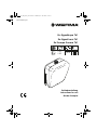
Ex-Signalhupe 761
Ex-Signal horn 761
Ex-Trompe Sonore 761
Betriebsanleitung
Instructions for use
Mode d’emploi
1500
g
IP 65
+50°C
-40°C
max.
105 dB
II 2G
II 2D
ATEX
310.761.008.0618_AA
310_761_008_0618_AA.fm Seite 1 Mittwoch, 27. Juni 2018 10:12 10

2
Inhaltsverzeichnis
1 Grundlegende Hinweise .......................................................... 3
2 Funktion ...................................................................................... 3
3 Konformität ................................................................................ 3
4 Sicherheitshinweise ................................................................... 3
5 Technische Daten ..................................................................... 4
6 Montage .................................................................................... 5
7 Inbetriebnahme ........................................................................ 5
8 Wartung ..................................................................................... 5
9 Reinigung ................................................................................... 5
10 Entsorgung ................................................................................. 5
Contents
1 Basic Remarks ............................................................................ 5
2 Function ..................................................................................... 5
3 Conformity ................................................................................. 6
4 Safety instructions ..................................................................... 6
5 Technical specifications ........................................................... 7
6 Mounting .................................................................................... 7
7 Commissioning .......................................................................... 7
8 Servicing ..................................................................................... 7
9 Cleaning .................................................................................... 7
10 Disposal ...................................................................................... 8
Sommaire
1 Informations fondamentales ................................................... 8
2 Fonctionnement ........................................................................ 8
3 Conformité ................................................................................. 8
4 Consignes de sécurité .............................................................. 8
5 Données techniques ................................................................ 9
6 Montage .................................................................................. 10
7 Mise en service ........................................................................ 10
8 Maintenance ........................................................................... 10
9 Nettoyage ............................................................................... 10
10 Réglementation concernant les déchets ............................ 10
11 Zeichnungen / Drawings / Dessins ........................................ 11
12 Anhang / Appendix / Annexes ..............................................13
310_761_008_0618_AA.fm Seite 2 Mittwoch, 27. Juni 2018 10:12 10

Funktion
3
1 Grundlegende Hinweise
1.1 Zweck dieses Dokuments
Diese Betriebsanleitung ist Voraussetzung zum sicheren und nutzungsgerech-
ten Gebrauch des Geräts. Sie muss deshalb vor Inbetriebnahme, vom Mon-
tage- und Wartungspersonal sorgfältig durchgelesen und beachtet werden.
Diese Anleitung leicht zugänglich und griffbereit aufbewahren.
1.2 Sicherheitssymbole
Dieses Symbol bedeutet eine möglicherweise gefährliche Situation.
Das Nichtbeachten der so gekennzeichneten Hinweise kann schwere
gesundheitsschädliche Auswirkungen zur Folge haben oder zu Sachbeschädi-
gungen führen.
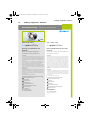
2 Funktion
Das Gerät wurde zum Warnen, Rufen und Melden in explosionsgefährdeten
Bereichen mit Gefährdung durch Gas oder Staub entwickelt. Die Geräteg-
ruppe II Kategorie 2 erlaubt den Einsatz in nahezu allen Gas- und Staub- Ex-
Zonen, in denen sich Personen aufhalten. Der Gas-Explosionsschutz wird durch
die Zündschutzarten Vergusskapselung „m“ und Erhöhte Sicherheit „e“ im
Anschlussbereich erreicht. Der Staub-Explosionsschutz wird durch das
Gehäuse IP65 T70 °C realisiert. Geeignet zum Einsatz in Bereichen mit brenn-
baren Stäuben mit einer Mindestzündenergie > 1 mJ.
3 Konformität
Das Gerät entspricht folgenden Richtlinien und Normen:
• 2014/34/EU (ATEX), 2014/30/EU (EMV), 2011/65/EU (RoHS)
• IEC/EN 60079-0, IEC/EN 60079-7, IEC/EN 60079-18, IEC/ EN 60079-31,
IEC/EN 60947-5-1, EN 50581
Normendatum laut EU-Konformitätserklärung
4 Sicherheitshinweise
• Das Gerät ist ausschließlich zur bestimmungsgemäßen Verwendung wie
unter „Funktion“ beschrieben vorgesehen. Andere Anwendungen sind ver-
boten, da bei sachwidrigem Gebrauch Gefahren auftreten können.
• Die nationalen Sicherheits- und Unfallvorschriften sind zu beachten.
• Wenn durch einen Ausfall des Signalgeräts eine Gefährdung von Men-
schen oder Beschädigung von Betriebseinrichtungen möglich ist, muss dies
durch zusätzliche Sicherheitsmaßnahmen verhindert werden.Die Hupe
schaltet bei Überhitzung durch zu langen Dauerbetreib ab und wird erst
nach Abkühlung wieder automatisch eingeschaltet.
• Das Gerät darf ausschließlich von Fachpersonal montiert und gewartet
werden, welches mit den geltenden Vorschriften und Bestimmungen ver-
traut ist.
• Der Anschluss der externer Zuleitung erfolgt unter Verwendung der Kabel-
verschraubung (M16 x 1,5)und im Anschlussraum unter dem Deckel (siehe
Zeichnungen ab Seite 11). Wenn die Kabelverschraubung Kunststoff ist, so
ist diese gegen Schlag geschützt zu montieren! Wenn die Kabelverschrau-
bung Metall ist, maximale Schlüsselweite 19 mm verwenden! Die Hinweise
D
310_761_008_0618_AA.fm Seite 3 Mittwoch, 27. Juni 2018 10:12 10

Technische Daten
4
und technischen Daten der Kabelverschraubung ebenfalls beachten! Die
Anschlussleitung fest verlegen sofern eine ungeschützte oder flexible Lei-
tung verwendet wird. Jeder Hupe als Kurzschlussschutz eine ihrem
Nennstrom entsprechende Sicherung vorschalten (siehe « Elektrische
Daten »).
• Vor Anschluss und bei Beschädigung des Geräts Versorgungs- bzw. Netz-
spannung abschalten und gegen unbeabsichtigtes Wiedereinschalten
sichern.
• Gerät nur in komplett montiertem, unbeschädigten Zustand betreiben.
ACHTUNG Gefahr durch Elektrostatik, deshalb gilt für IIG:
Reinigung nur mit feuchtem Tuch
• Nennspannung beachten.
• Sicherung gemäß Tabelle 5.2 vorschalten.
• Der Schalldruck kann bei geringem Abstand das Gehör schädigen.
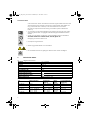
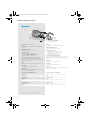
5 Technische Daten
5.1 Allgemeine Daten
5.2 Elektrische Daten
Material PC, schwarz
Maße 178 mm x 207 mm x 104 mm
Gewicht 1500 g
Schalldruck max. 105 dB
Einsatz-Temperaturbereich -40 °C ... + 50 °C
Einschaltdauer ED 70%
Schutzart nach IEC 60529 IP 65
Kennzeichnung für Gas
II 2G Ex eb mb IIC T5 Gb
Kennzeichnung für Staub
II 2D Ex tb IIIC T70°C Db
Prüfbescheinigung BVS 03 ATEX E 118X
Typ Nennspannung Spannungs-
bereich
Nenn-
strom
Vorzuschaltende
Sicherung,
761 000 55 24 V= 21,6 ... 26,4 V 350 mA F 0,5 A
761 000 65 24 V~, 50 Hz 21,6 ... 26,4 V 450 mA F 0,63 A
761 000 66 42 V - 48 V~, 50 Hz 37,8 ... 52,8 V 220 mA F 0,315 A
761 000 67 115 V~, 50/60 Hz
120 V~, 60 Hz
102,5 ... 126,5 V
108 ... 131 V
205 mA
220 mA
F 0,315 A
761 000 68 230 V~, 50 Hz 208 ... 250 V 70 mA F 0,125 A
OFF
NENNSPANNUNG
NOMINAL VOLTAGE
TENSION NOMINALE
max. 105 dB
310_761_008_0618_AA.fm Seite 4 Mittwoch, 27. Juni 2018 10:12 10

Montage
5
6 Montage
Abmessungen und Montage siehe “Zeichnungen / Drawings / Dessins” ab
Seite 11.
7 Inbetriebnahme
Vor der Inbetriebnahme sicherstellen, dass:
• das Gerät vorschriftsmäßig montiert wurde,
• der elektrische Anschluss ordnungsgemäß ausgeführt wurde,
• die richtige Sicherung lt. Pkt. 5.2 vorgeschaltet wurde,
• das Gerät nicht beschädigt ist.
8 Wartung
Das Gerät ist wartungsfrei
9 Reinigung
Zone 1:
• Reinigung nur mit einem feuchten Tuch, dazu Wasser oder milde, nicht
scheuernde, nicht kratzende Reinigungsmittel verwenden. Niemals aggres-
sive Reinigungsmittel oder Lösungsmittel verwenden.
Zone 21:
• Reinigung mit einem Tuch, Besen, Staubsauger o.a. Bei feuchter Reinigung
Wasser oder milde, nicht scheuernde, nicht kratzende Reinigungsmittel ver-
wenden. Niemals aggressive Reinigungsmittel oder Lösungsmittel verwen-
den.
10 Entsorgung
Bei der Entsorgung sind die nationalen Abfallbeseitigungsvorschriften zu
beachten!
1 Basic Remarks
1.1 Purpose of the document
This operating manual is necessary for the safe and appropriate use of the
appliance, and as such must be read carefully by assembly and mainte-
nance staff before commissioning, and observed in all respects. This manual
must be kept read to hand in an easily accessible place.
1.2 Safety symbols
This symbol indicates a possibly dangerous situation.
The disregard of indicated hazards can result in serious harm to health or lead
to material damage.
2 Function
The appliance was developed as a signalling device for warning in hazardous
areas where flammable dust or gas is present. The device group II category 2
permits use in almost all gas and dust Ex zones in which persons are present.
GB
310_761_008_0618_AA.fm Seite 5 Mittwoch, 27. Juni 2018 10:12 10

Conformity
6
The gas explosion protection is achieved by casting compound protection
“m” as well as increased safety “e” in the area of the electrical connection.
The dust explosion protection is achieved through the housing IP65 T70 °C.
Suitable for use in areas with flammable dust with a minimum firing power
>1mJ.
3 Conformity
The appliance meets the following directives and standards:
• 2014/34/EU (ATEX), 2014/30/EU (EMC), 2011/65/EU (RoHS)
• IEC/EN 60079-0, IEC/EN 60079-7, IEC/EN 60079-18, IEC/ EN 60079-31,
IEC/EN 60947-5-1, EN 50581
Normdates as detailed in declaration of conformity
4 Safety instructions
• The appliance is exclusively intended for the designated use described in
article 2 “Function”. Other applications are prohibited, as inappropriate
use can result in dangerous situations.
• National safety and accident regulations must be observed.
• In case of equipment failure, additional safety precautions should be taken
to avoid possible danger to persons.
• Should the horn overheat due to excessively long operation it will shut
down and automatically restart once it has cooled down.
• Wiring must be carried out by a qualified electrician. Adhere to relevant
regulations!
• The connection to external supply lines must be carried out using a
screwed cable gland (M16 x 1,5) in the terminal box under the cover (see
drawings from page 11). If a plastic screwed cable gland is used, it must be
mounted with impact protection! If a metal screwed cable gland is used,
the maximum spanner size is 19 mm! Respect instructions and technical
data for the screwed cable gland! Install a fixed connection cable if an
unprotected or flexible cable is used. Each horn only to be operated with
short circuit protection connected in series, i.e. with a fuse corresponding
to its rated current (ref. « Electrical data »).
• Turn off the power supply and take steps to ensure against further acciden-
tal use:
- Before connection.
- In the event of damage
• Only operate the appliance when completely assembled.
ATTENTION Danger due to electrostatics, therefore condition IIG applies:
Cleaning only with a damp cloth
• Observe the nominal voltage.
• Install the right fuse in accordance with 5.2.
OFF
NENNSPANNUNG
NOMINAL VOLTAGE
TENSION NOMINALE
310_761_008_0618_AA.fm Seite 6 Mittwoch, 27. Juni 2018 10:12 10

Technical specifications
7
• The sound pressure can cause damage to hearing when used at close
quarters.
5 Technical specifications
5.1 General data
5.2 Electrical data
6 Mounting
For dimensions and mounting see “Zeichnungen / Drawings / Dessins”
page 11.
7 Commissioning
Before commissioning make sure that:
• the appliance has been mounted according to instructions,
• the electrical connections have been carried out correctly,
• the right fuse in accordance with 5.2 has been installed,
• the appliance is not damaged in any way.
8 Servicing
The appliance is maintenance-free
9 Cleaning
• Zone 1: Clean only with a damp cloth using water or mild non-chafing,
non-scratching cleaning fluid. Never use aggressive substances or solvents
when cleaning.
Material PC, black
Dimensions 178 mm x 207 mm x 104 mm
Weight 1500 g
Sound pressure max. 105 dB
Temperature range -40 °C ... + 50 °C
Duty cycle 70%
Protection type according to IEC 60529 IP 65
Explosion protection for gas
II 2G Ex eb mb IIC T5 Gb
Explosion protection for dust
II 2D Ex tb IIIC T70°C Db
Test certificate BVS 03 ATEX E 118X
Type Rated current Voltage range Current
consumption
Fuse to be
connected in series
761 000 55 24 V= 21,6 ... 26,4 V 350 mA F 0,5 A
761 000 65 24 V~, 50 Hz 21,6 ... 26,4 V 450 mA F 0,63 A
761 000 66 42 V - 48 V~, 50 Hz 37,8 ... 52,8 V 220 mA F 0,315 A
761 000 67 115 V~, 50/60 Hz
120 V~, 60 Hz
102,5 ... 126,5 V
108 ... 131 V
205 mA
220 mA
F 0,315 A
761 000 68 230 V~, 50 Hz 208 ... 250 V 70 mA F 0,125 A
max. 105 dB
310_761_008_0618_AA.fm Seite 7 Mittwoch, 27. Juni 2018 10:12 10

Disposal
8
• Zone 21: Clean with a cloth, brush, vacuum-cleaner or similar. For wet
cleaning use water or mild non-chafing, non-scratching cleaning fluid.
Never use aggressive substances or solvents when cleaning.
10 Disposal
Observe national waste disposal regulations when disposing of the appliance!
1 Informations fondamentales
1.1 Objectif de ce document
Cette notice d’utilisation est garante d’une utilisation conforme et sûre de
l’appareil. Elle doit, pour cette raison, avoir été lue consciencieusement avant
la mise en service de l’appareil par les personnels de montage et de mainte-
nance qui se doivent de la respecter. Cette notice doit toujours se trouver à
portée de la main dans un endroit facilement accessible.
1.2 Symboles de sécurité
Ce symbole indique une situation potentiellement dangereuse.
Ce symbole indique une situation potentiellement dangereuse.
Le non-respect des notes marquées de ce symbole peut avoir des consé-
quences graves pour la santé ou conduire à des dommages matériels.
2 Fonctionnement
L'appareil a été développé pour l'avertissement, l'appel et la signalisation
dans les environnements exposés aux risques d'explosion. Cet appareil appar-
tient au Groupe II Catégorie 2 et peut être utilisé pour la signalisation dans
pratiquement tous les environnements explosibles « Ex », dans lesquels sont
présents des individus. La protection antidéflagrante « gaz » est assurée par
l'encapsulage «m» et par la mesure de sécurité renforcée « e » dans la zone
des branchements électriques. La protection antidéflagrante « poussière » est
assurée par le boîtier IP65 T70°C. Cet appareil convient pour utilisation dans
des zones à risque de poussière inflammables >1mJ.
3 Conformité
L’appareil répond aux normes et directives suivantes :
• 2014/34/EU (ATEX), 2014/30/EU (CEM), 2011/65/EU (RoHS)
• IEC/EN 60079-0, IEC/EN 60079-7, IEC/EN 60079-18, IEC/ EN 60079-31,
IEC/EN 60947-5-1, EN 50581
Dates de normes selon la déclaration de conformité de l'UE
4 Consignes de sécurité
• L’appareil est uniquement destiné à l’utilisation décrite au point
« fonctionnement ». Toute autre utilisation est interdite du fait des dangers
pouvant provenir d’une utilisation non-conforme.
• Les directives nationales de sécurité et de protection contre les accidents
doivent être respectées.
• Si une panne ou un défaut de l’avertisseur présentait un danger pour le
F
310_761_008_0618_AA.fm Seite 8 Mittwoch, 27. Juni 2018 10:12 10

Données techniques
9
personnel ou les installations, des mesures de sécurité supplémentaires
doivent être mises en place pour prévenir celui-ci.
• En cas d’une surchauffe due à un fonctionnement continu, l’avertisseur
s’éteindra pour redémarrer automatiquement.
• Branchement à effectuer par un électrotechnicien confirmé. Respecter les
instructions spécifiques.
• Le branchement du câble externe se fait par passe-câble à vis (M16 x 1,5)
et est réalisé dans le bornier sous le couvercle (voir les dessins à partir de la
page 11). Lorsque le passe-câble à vis est en plastique, le montage de
celui-ci doit être fait de manière à la protéger des décharges électriques !
Lorsque le passe-câble à vis est métallique, utiliser une clef de largeur maxi-
mum 19 mm. Respecter également les indications et les caractéristiques
techniques concernant le vissage du câble ! Si un câble souple ou non
blindé est utilisé, le fixer. Chaque avertisseur doit fonctionner avec une pro-
tection de court-circuit montée en série avec un fusible approprié au cou-
rant nominal (voir les « Caractéristiques électriques »).
• Avant de connecter l'appareil et en cas de défaut de celui-ci, couper la
tension du réseau. Prendre des mesures de sécurité pour éviter toute
remise en marche accidentelle.
• N’employer l’appareil que lorsqu’ il est complètement monté.
ATTENTION Danger dû à l'électrostatique, donc la condition IIG s'applique:
Nettoyage uniquement avec un chiffon humide.
• Respecter la tension nominale indiquée.
• Installer le fusible selon le tableau 5.2.
• La puissance sonore peut nuire à l'ouïe en cas de trop grande proximité.
5 Données techniques
5.1 Caractéristiques générales
Matériaux PC, noir
Dimension 178 mm x 207 mm x 104 mm
Poids 1500 g
Puissance sonore max. 105 dB
Plage thermique d’utilisation -40 °C ... +50 °C
Facteur de marche 70%
Fusible selon IEC 60529 IP 65
Classe d’appareil pour fonctionnement
en zone explosible « gaz »
II 2G Ex eb mb IIC T5 Gb
OFF
NENNSPANNUNG
NOMINAL VOLTAGE
TENSION NOMINALE
max. 105 dB
310_761_008_0618_AA.fm Seite 9 Mittwoch, 27. Juni 2018 10:12 10

Montage
10
5.2 Caractéristiques électriques
6 Montage
Dimensions et montage, voir « Zeichnungen / Drawings / Dessins » à partir de
la page 11.
7 Mise en service
Avant la mise en service, s’assurer que :
• l’appareil soit correctement monté,
• le branchement électrique ait été réalisé dans les règles,
• le fusible correct selon 5.2. a été installé,
• l’appareil ne soit pas endommagé.
8 Maintenance
L’appareil est sans entretien
9 Nettoyage
Zone 1:
• Nettoyez uniquement avec un chiffon humide en utilisant de l’eau ou du
détergent doux non corrosif pour éviter les rayures. N‘utilisez jamais de pro-
duits agressifs ou de solvants pour le nettoyage.
Zone 21:
• Nettoyez avec un chiffon, une brosse, un aspirateur ou autre ustensile simi-
laire. Pour un nettoyage humide, utilisez de l’eau ou du détergent doux
non corrosif pour éviter les rayures. N‘utilisez jamais de produits agressifs ou
de solvants pour le nettoyage.
10 Réglementation concernant les déchets
Lors de l’élimination de l’appareil, respecter la législation nationale en vigueur
sur l’élimination des déchets!
Classe d’appareil pour fonctionnement
en zone explosible « poussières »
II 2D Ex tb IIIC T70°C Db
Certificat BVS 03 ATEX E 118X
Type Tension normale Tolérance Consommation
moyenne
Fusible de à monter
en série.
761 000 55 24 V= 21,6 ... 26,4 V 350 mA F 0,5 A
761 000 65 24 V~, 50 Hz 21,6 ... 26,4 V 450 mA F 0,63 A
761 000 66 42 V - 48 V~, 50 Hz 37,8 ... 52,8 V 220 mA F 0,315 A
761 000 67 115 V~, 50/60 Hz
120 V~, 60 Hz
102,5 ... 126,5 V
108 ... 131 V
205 mA
220 mA
F 0,315 A
761 000 68 230 V~, 50 Hz 208 ... 250 V 70 mA F 0,125 A
310_761_008_0618_AA.fm Seite 10 Mittwoch, 27. Juni 2018 10:12 10

Zeichnungen / Drawings / Dessins
11
11 Zeichnungen / Drawings / Dessins
1a)
1b)
2, 3)
max.
Ø6,5 mm
0.26”
178 mm
7.01”
22 mm
0.87”
160 mm
6.30”
207 mm
8.15”
130 mm
5.12”
104 mm
4.10”
oben
top
en haut
unten
bottom
en bas
max. 90°
max. 90°
max. 90°
Boden oder Wandmontage - Gerät niemals mit
Schallaustritt nach oben montieren.
Surface or wall mounting - never install the appli-
ance with sound exit upwards.
Montage sur fond plat ou équerre: ne jamais
monter l‘appareil avec la sortie sonore vers le
haut.
1.
2.
3.
7mm
0.28”
1,5mm²
AWG 18-14
£
Ø 6,5-9,5 mm
0.22”-0.37”
2 Adern
2 Wires
2 Conduct.
35mm
1.38”
£
IP65!
Kabelverschraubung montieren und gut festziehen.
Mount cable gland and screw tightly into place.
Monter le passe-câble à vis et le
visser fermement.
M16 x 1,5
M16x1,5 (-40 °C)
IIG/IID
310_761_008_0618_AA.fm Seite 11 Mittwoch, 27. Juni 2018 10:12 10

Zeichnungen / Drawings / Dessins
12
4a, b)
5)
6)
2.
1.
br
bl
(L)
(N)
br
bl
+-
+
-
761 000 55
761 000 65
761 000 66
761 000 67
761 000 68
IP 65!
Überwurfmutter gut festziehen.
Screw nut firmly into place.
Visser fermement l'écrou-raccord.
IP54
3.
1.
2.
Gerät darf ohne mitgelieferte Dichtung nicht
betrieben werden.
Do not use appliance without seal included in
assembly.
Ne pas faire fonctionner l’appareil sans le joint
fourni pour le montage.
310_761_008_0618_AA.fm Seite 12 Mittwoch, 27. Juni 2018 10:12 10

Anhang / Appendix / Annexes
13
12 Anhang / Appendix / Annexes
Betriebsanleitung · Operating instructions
0102
PTB 11 ATEX 1007X
blueglobe
®
HT Ex e
Messing vernickelt/blank und
Edelstahl
Für Kabel- und Leitungseinführungen (KLE)
der Zündschutzart „Erhöhte Sicherheit – Ex „e“
Anwendung:
Die Kabel- und Leitungseinführungen (KLEs) blueglobe
®
HT Ex e die-
nen zur Einführung von fest verlegten Kabeln und Leitungen in einen
Anschlussraum oder in ein Gehäuse eines explosionsgeschützten elek-
trischen Betriebsmittels der Gerätegruppe II und der Kategorien 2 G/D
und 3 G/D.
Der Anschlussraum oder das Gehäuse muss der Zündschutzart „Er-
höhte Sicherheit – Ex „e“nach den Normen EN 60079-0:2012 +
A11:2013, EN 60079-7:2015, EN 60079-31:2014 entsprechen.
Die KLE ist für Betriebsmittel mit dem Grad der mechanischen Gefahr
„hoch“ nach EN 60079-0 geeignet. Bei ordnungsgemäßer Montage
der KLE kann die Schutzart IP 66/68 nach IEC 529 oder EN 60529
erreicht werden.
Kennzeichnung:
Die Kabel- und Leitungseinführungen blueglobe
®
HT Ex e entsprechen
den Normen EN 60079-0:2012 + A11:2013, EN 60079-7:2015, EN
60079-31:2014. Sie sind von der Physikalisch-Technischen Bundes-
anstalt (PTB) einer EG-Baumusterprüfung nach EG-Richtlinie 94/9/EG
unterzogen worden.
Sie sind deshalb wie folgt gekennzeichnet:
Kennzeichnung Zulassungsnummer und Kennzeichen der Prüfstelle:
` PTB 11 ATEX 1007X xx C 0102
Kennzeichnung Gas:
` II 2G Ex e IIC Gb
Kennzeichnung Staub:
` II 2D Ex tb IIIC Db IP 66/68
Kennzeichnung extrem kleiner Bauteile:*
` II 2G/II 2D C 0102
Weitere Zertifikate:
IECEx – IECEx PTB 11.0019X
EAC – RU C-DE.M
ॆ06.B.00002
PTB 11 ATEX 1007X
blueglobe
®
HT Ex e
brass nickel-plated, brass and stain-
less steel
For cable glands and cable entry systems (CG/CES) of the
ignition protective class Ex “e”
Application:
The cables glands and cable entry systems (CG/CES) blueglobe
®
HT Ex
e are used to insert permanently laid lines and cables into a connection
space or housing of an explosion-protected electrical operating ma-
terial of the appliance group II and categories 2 G/D and 3 G/D. The
connection space or housing must conform to the ignition protective
class “Increased safety – Ex e” in accordance with the standards EN
60079-0:2012 + A11:2013, EN 60079-7:2015 and EN 60079-31:2014.
The CG/CES is suitable for operating material with the degree of me-
chanical risk “high” as per EN 60079-0. In selecting the material for the
sealing insert, the ambient, surface and operating temperature at the
installation point is to be observed. With proper assembly of the KLE,
the protective class IP 66/68 according to IEC 529 or EN 60529 can be
attained.
Designation:
The cable glands and cable entry systems (CG/CES) blueglobe
®
HT Ex e
conform with the standards EN 60079-0:2012 + A11:2013, EN 60079-
7:2015, EN 60079-31:2014. They were subjected to an EC design test
in accordance with EC directive 94/9/EC by the Physical-Technical Fed-
eral Institute (PTB).
They are therefore designated as follows:
ID of approval no. and ID of testing authority:
` PTB 11 ATEX 1007X xx C 0102
Designation gas:
` II 2G Ex e IIC Gb
Designation dust:
` II 2D Ex tb IIIC Db IP 66/68
Designation of extremely small components:*
` II 2G/II 2D C 0102
ID of Approval IECEx:
IECEx – IECEx PTB 11.0019X
EAC – RU C-DE.M
ॆ06.B.00002
*Designation on cable gland
310_761_008_0618_AA.fm Seite 13 Mittwoch, 27. Juni 2018 10:12 10

Anhang / Appendix / Annexes
14
2 · Betriebsanleitung 1007X bg HT Ex-e/Operating instruction 1007X bg HT Ex-e
*Kennzeichnung auf Kabelverschraubung
Montage
Als Montagewerkzeug kann der PFLITSCH Steckschlüssel M28 verwen-
det werden.
Einsatztemperaturbereich:
Temperaturbereich Silikon: -55 °C bis +160 °C
Mindestwandstärken
· beim Einbau in Geräten mit Gewindebohrungen:
s = 5,0 mm (Kunststoff); 3,0 mm (Metall)
· beim Einbau in Geräten mit Durchgangsbohrungen:
s = 2,0 mm (Kunststoff); 1,0 mm (Metall)
Hinweis zur Zugentlastung der Kabelverschraubung:
Die KLE ist nur für fest verlegte Leitungen und Kabel geeignet. Der
Betreiber muss in diesem Fall für geeignete Maßnahmen sorgen, um
eine Zugentlastung zu gewähren.
Wichtig:
Dichtringe dürfen nicht mit dem Messer ausgeschnitten werden!
Demontage:
Die Demontage erfolgt in umgekehrter Reihenfolge.
Instandhaltung:
Die Blindstopfen sind in die Kontrollen bei der Inspektion und Wartung
der elektrischen Betriebsmittel einzubeziehen.
Assembly
The PFLITSCH socket spanner M28 can be used as a tool
Application temperature range:
Temperature range silicone: -55 °C bis +160 °C
Minimum wall thicknesses
· for installation in appliances with threaded holes:
s = 5.0 mm (plastic); 3.0 mm (metal)
· for installation in appliances with throughholes:
s = 2.0 mm (plastic); 1.0 mm (metal)
Pointer for strain relief of the cable gland:
The CG/CES are only suitable for permanently laid lines and cables.
In this case, the operator must adopt appropriate measures to ensure
strain relief.
Important:
Sealing rings must not be cut out with a knife!
Disassembly:
Disassembly is carried out in the reverse order.
Maintenance:
The CG/CES are to be included in the inspection and maintenance of
the electrical operating material.
Kabel
cable
Druckschraube
pressure screw
Dichteinsatz 2-tlg.
Two-part sealing
insert
Doppelnippel
double nippel
O-Ring
o-ring
Anzugsmomente: Tightening torques:
Gewinde/Thread
M12 M16 M20 M25 M32 M40
Nm
5 8 10151520
Mechanische Festigkeit: Mechanical strength:
Gewinde/Thread
M12 M16 M20 M25 M32 M40
Joule
777777
Anschlussmaße für Durchgangsbohrungen: Connection dimensions for throughholes:
Metrisch/metric
M12 M16 M20 M25 M32 M40
d [mm] 0/+ 0,3
12,0 16,0 20,0 25,0 32,0 40,0
l
l
l
l
l
l
310_761_008_0618_AA.fm Seite 14 Mittwoch, 27. Juni 2018 10:12 10

Anhang / Appendix / Annexes
15
Betriebsanleitung 1007X bg HT Ex-e/Operating instruction 1007X bg HT Ex-e · 3
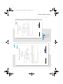
EU-Konformitätserklärung
ausgestellt von:
PFLITSCH GmbH & Co. KG
'TPUV2ƃKVUEJ5VTC»G
)
0QTF
&*ØEMGUYCIGP
2TQFWMVDG\GKEJPWPI Kabel- und Leitungseinführung aus Messing und Messing vernickelt
Kabel- und Leitungseinführung aus Edelstahl
Zubehör Blindstopfen, Erweiterungen und Reduzierungen aus Metall
6[RGPDG\GKEJPWPI Art.-Gr.: UNI Ex* Gewinde: Metrisch/Pg/NPT/Zoll PTB 14 ATEX 1011X
Art.-Gr.: UNI Ex Klemm* Gewinde: Metrisch/Pg/NPT/Zoll PTB 14 ATEX 1012
Art.-Gr.: UNI Ex* Silikon Gewinde: Metrisch/Pg/NPT/Zoll PTB 15 ATEX 1001X
Art.-Gr.: Zubehör Ex-e Gewinde: Metrisch/Pg PTB 09 ATEX 1002
Art.-Gr.: blueglobe
®
HT Ex-e Gewinde: Metrisch PTB 11 ATEX 1007X
Art.-Gr.: blueglobe
®
Ex-e Gewinde: Metrisch PTB 06 ATEX 1036X
Das bezeichnete Produkt erfüllt die Bestimmungen der Richtlinie:
'7
d4KEJVNKPKGFGU'WTQRÀKUEJGP2CTNCOGPVUWPFFGU4CVGUXQO(GDTWCT\WT*CTOQPKUKGTWPIFGT4GEJVUXQTUEJTKHVGPFGT/KVINKGF-
UVCCVGPHØT)GTÀVGWPF5EJWV\U[UVGOG\WTDGUVKOOWPIUIGOÀ»GP8GTYGPFWPIKPGZRNQUKQPUIGHÀJTFGVGP$GTGKEJGP0GWHCUUWPIp
$CUKULeitfaden der ATEX-Richtlinie Übergang von 94/9/EC zu 2014/34/EU
Die Übereinstimmung des bezeichneten Produktes mit den Bestimmungen der Richtlinie wird durch die vollständige Einhaltung folgender Normen
nachgewiesen:
EN 60079-0:2012 + A11:2013
EN 60079-7:2015
EN 60079-31:2014
Die Physikalisch Technische Bundesanstalt (EU-Kenn-Nr.: 0102), Bundesallee 100, 38116 Braunschweig, hat das Produkt geprüft und zertifiziert.
Die EG-Baumusterprüfbescheinigungen berechtigten zum Führen des Zeichens der PTB.
Hückeswagen, 21.11.2016
(Ort, Datum) (Rechtsverbindliche Unterschrift des Ausstellers, Ex-Beauftragter)
Dieses Schreiben ist per EDV erstellt und hat auch ohne eigenständige Unterschrift für uns rechtsverbindlichen Charakter.
Betriebsanleitung_1007X_blueglobe_HT_ex_e_95811/Stand: 07.2017 · PFLITSCH GmbH & Co. KG
Irrtümer und technische Änderungen vorbehalten.
Errors and technical alterations are reserved.
PFLITSCH GmbH & Co. KG
$QMRS/×HSRBG2SQ@¦D
)
Nord 1
D-42499 Hückeswagen
Telefon: +49 2192 911-0
Fax: +49 2192 911-220
$,@HK HMENO×HSRBGCD
(MSDQMDS VVVO×HSRBGCD
EU Declaration of Conformity
issued by:
PFLITSCH GmbH & Co. KG
'TPUV2ƃKVUEJ5VTC»G
)
0QTF
&*ØEMGUYCIGP
Product: Cable and conduit entry made of brass and brass nickel plated
Cable and conduit entry made of stainless steel
Accessories blind plugs, reducers and extensions made of metal
Type designation: Art. gr.: UNI Ex* Connection thread: metric/Pg/NPT/Inch PTB 14 ATEX 1011X
Art. gr.: UNI Ex Clamping* Connection thread: metric/Pg/NPT/Inch PTB 14 ATEX 1012
Art. gr.: UNI Ex* Silicone Connection thread: metric/Pg/NPT/Inch PTB 15 ATEX 1001X
Art. gr.: Accessories Ex-e Connection thread: metric/Pg PTB 09 ATEX 1002
Art. gr.: blueglobe
®
HT Ex-e Connection thread: metric PTB 11 ATEX 1007X
Art. gr.: blueglobe
®
Ex-e Connection thread: metric PTB 06 ATEX 1036X
The designated product is in conformity with the European Directive:
2014/34/EU
Guideline of the European Parliament and of the council of 26 February 2014 on the harmonisation of the laws of the Member States
relating to equipment and protective systems intended for use in potentially explosive atmospheres (recast).
Basis: Guidance document on the ATEX directive transition from 94/9/EC to 2014/34/EU
Full compliance with the standards listed below proves the conformity of the designated product with the provisions of the above mentioned directive:
EN 60079-0:2012 + A11:2013
EN 60079-7:2015
EN 60079-31:2014
The „Physikalisch Technische Bundesanstalt“ (EU-Kenn- Nr.: 0102 ), Bundesallee 100, 38116 Braunschweig, has tested and certified the
product granting the PTB Marks Licence for the mark(s).
Hückeswagen, 21.11.2016
(Place, date) (Legally binding signature of the issuer, Ex representative)
This Letter is prepared by EDP and has a legally binding character for us also without an independent signature.
310_761_008_0618_AA.fm Seite 15 Mittwoch, 27. Juni 2018 10:12 10

Anhang / Appendix / Annexes
16
EU-Konformitätserklärung
EU Declaration of Conformity
311.761.001
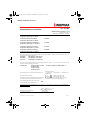
2018-03-19/ 311.761.001-01AF.docx 1/1 QM65-96
WERMA Signaltechnik GmbH + Co. KG
Dürbheimer Straße 15
78604 Rietheim-Weilheim / Germany
Ex-Signalhupe WM Dauerton 24VDC / 761 000 55
Ex Signal horn WM Contin. tone 24VDC
Ex-Signalhupe WM Dauerton 24VAC / 761 000 65
Ex Signal horn WM Contin. tone 24VAC
Ex-Signalhupe WM Dauerton 42-48VAC / 761 000 66
Ex Signal horn WM Contin. tone 42-48VAC
Ex-Signalhupe WM Dauerton 115VAC / 761 000 67
Ex Signal horn WM Contin. tone 115VAC
Ex-Signalhupe WM Dauerton 230VAC / 761 000 68
Ex Signal horn WM Contin. tone 230VAC
Wir erklären in alleiniger Verantwortung, dass die o.g. Produkte mit den folgenden Europäischen Richt-
linien übereinstimmen. / We declare under our sole responsibility that above named products are in con-
formity with the following directives.
2014/30/EU EMV Richtlinie / EMC Directive
2014/34/EU Atex-Richtlinie / Atex Dirctive
2011/65/EU RoHS Richtlinie / RoHS Directive
Dies wird nachgewiesen durch die Einhaltung folgender Normen. / This is documented by the ac-
cordance with the following standards:
EN 50581:2012 EN 60079-0:2012:+A11:2013 EN 60947-5-1:2004+Cor.:2005+A1:2009, 7.3
EN 60079-7:2015
EN 60079-18:2015
EN 60079-31:2014
Bescheinigungsnr. / Examination certification No:
BVS 03 ATEX E118 X,
1. Supplement , 2. Supplement , 3. Supplement, 4.
Supplement
Kennzeichnung / Marking:
0102
II 2G Ex eb mb IIC T5 Gb
II 2D Ex tb IIIC T70°C Db
Die benannte Stelle für Fertigungsüberwachung ist/
The notified body responsible for monitoring is:
PTB (Registriernummer/Identification-no: 0102)
Bundesallee 100, D-38116 Braunschweig
Jahr der Erstanbringung des CE-Zeichens:
Year of Qualification for the CE-mark
2004
Die Hinweise der Montageanleitung sind zu beachten. / The advice contained in the installation instruc-
tion is to be observed.
Rietheim, den 12.09.2017
ppa. Höhler
Ort, Datum der Ausstellung
Place and date of issue
Entwicklungsleiter
Research and Development Director
310_761_008_0618_AA.fm Seite 16 Mittwoch, 27. Juni 2018 10:12 10

310_761_008_0618_AA.fm Seite 17 Mittwoch, 27. Juni 2018 10:12 10

310_761_008_0618_AA.fm Seite 18 Mittwoch, 27. Juni 2018 10:12 10

310_761_008_0618_AA.fm Seite 19 Mittwoch, 27. Juni 2018 10:12 10

310_761_008_0618_AA.fm.27.6.18.www.krea-team.de
Technische Änderungen vorbehalten
Subject to technical modifications
Sous réserve de modifications techniques
310.761.008.0618_AA
© D
310_761_008_0618_AA.fm Seite 20 Mittwoch, 27. Juni 2018 10:12 10
-
 1
1
-
 2
2
-
 3
3
-
 4
4
-
 5
5
-
 6
6
-
 7
7
-
 8
8
-
 9
9
-
 10
10
-
 11
11
-
 12
12
-
 13
13
-
 14
14
-
 15
15
-
 16
16
-
 17
17
-
 18
18
-
 19
19
-
 20
20


werma 761 000 66 Instructions For Use Manual
- Type
- Instructions For Use Manual
- This manual is also suitable for
Ask a question and I''ll find the answer in the document
Finding information in a document is now easier with AI
in other languages
- français: werma 761 000 66
- Deutsch: werma 761 000 66
Other documents
-
IFM EVC04A Operating instructions
-
KILLARK R & RE Series Reducers Installation guide
-
Pulsar AWO604 Operating instructions
-
Woods WPF-100 Series Technical Manual
-
Chalmit lighting NexLED ATEX-IEC Installation guide
-
Eaton Crouse-Hinds GHG 960 1944 R Series Operating Instructions Manual
-
Parkside PDM 300 C3 Digital Auto-Range Multimeter User manual
-
Gossen MetraWatt KINAX HW730 Operating instructions
-
SEVERIN BC 7055 Owner's manual
-
Rittal KEL 9416 Assembly And Operating Instructions Manual