Elenco EP130 Owner's manual

Type
Owner's manual
Copyright © 2015, 2009 by Elenco
®
Electronics, Inc. All rights reserved. REV-C Revised 2015 753039
No part of this book shall be reproduced by any means; electronic, photocopying, or otherwise without written permission from the publisher.
ELECTRONIC
PLAYGROUND
TM
and LEARNING CENTER
MODEL EP-130
ELENCO
®
Wheeling, IL, USA
EP-130_62315RevC.qxp_EP-130_062812 6/23/15 11:16 AM Page 1
-2-
TABLE OF CONTENTS
Before We Begin Page 4
Installing the Batteries 4
Making Wire Connections 5
Components 5
Building Your First Project 9
Troubleshooting 10
Helpful Suggestions 10
I. PLAYGROUND OF ELECTRONIC CIRCUITS 11
1. Woodpecker 12
2. Police Siren 13
3. Metronome 14
4. Grandfather Clock 15
5. Harp 16
6. Tweeting Bird 17
7. Meowing Cat 18
8. Calling’ Fish 19
9. Strobe Light 20
10. Sound Effects for Horror Movies 21
11. Machine Gun Oscillator 22
12. Motorcycle Mania 23
13. Vision Test 24
14. Patrol Car Siren 25
II. BASIC ELECTRONICS CIRCUITS
26
A MAJOR CHANGE 27
15. Dimming the Light 28
16. Flip Flopping 29
17. Capacitor Discharge Flash 30
18. Transistor Action 31
19. Series and Parallel Capacitors 32
20. Transistor Switching 33
21. Series and Parallel Resistors 34
22. Amplify the Sound 35
III. LED DISPLAY CIRCUITS 36
23. LED Display Basics 37
24.
Digital Display Circuit for the Seven-Segment LED
38
25. LED Display with CdS and Transistor 39
26.
Switching the LED Display Using Transistor Control
40
IV. WELCOME TO DIGITAL CIRCUITS 41
27. “Flip-Flop” Transistor Circuit 42
28. “Toggle Flip-Flop” Transistor 43
29. “AND” Diode Transistor Logic with LED Display 44
30. “OR” DTL Circuit with Display 45
31. “NAND” DTL Circuit with Display 46
32. “NOR” Transistor Circuit with Display 47
33. “Exclusive OR” DTL Circuit 48
V. MORE FUN WITH DIGITAL CIRCUITS 49
34. “BUFFER” GATE using TTL 50
35. “INVERTER” GATE using TTL 51
36. “AND” GATE using TTL 52
37. “OR” GATE using TTL 53
38. “R-S Flip-Flop” using TTL 54
39. “Triple-Input AND” Gate using TTL 55
40. “AND” Enable Circuit using TTL 56
41. “NAND” Enable Circuit using TTL 57
42. “NOR” Enable Circuit using TTL 58
43. “NAND” Gate Making a Toggle Flip-Flop 59
44. “Exclusive OR” GATE using TTL 60
45. “OR” Enable Circuit using TTL 61
46. Line Selector using TTL 62
47. Data Selector using TTL 63
I
mportant: If you encounter any problems with this kit, DO NOT RETURN TO RETAILER. Call toll-free (800) 533-
2441 or e-mail us at: [email protected]. Customer Service • 150 Carpenter Ave. • Wheeling, IL 60090 U.S.A.
Do not short circuit the battery
terminals.
Never throw batteries in a fire or
attempt to open its outer casing.
Use only 1.5V AA” type, alkaline
batteries (not included).
Insert batteries with correct polarity.
Do not mix alkaline, standard (carbon-
zinc), or rechargeable (nickel-
cadmium) batteries.
Non-rechargeable batteries should not
be recharged. Rechargeable batteries
should only be charged under adult
supervision, and should not be
recharged while in the product.
Do not mix old and new batteries.
Remove batteries when they are used
up.
Batteries are harmful if swallowed, so
keep away from small children.
WARNING: Always check your wiring before
t
urning on a circuit. Never leave a circuit
unattended while the batteries are installed.
Never connect additional batteries or any
other power sources to your circuits.
WARNING:
CHOKING HAZARD - Small parts.
Not for children under 3 years.
Conforms to all applicable U.S. government
requirements.
Batteries:
!
EP-130_62315RevC.qxp_EP-130_062812 6/23/15 11:16 AM Page 2
-3-
V
I. MEET TRANSISTOR-TRANSISTOR LOGIC
64
48. Blinking LEDs 65
49. Machine Sound 66
50. Astable Multivibrator Using TTL 67
51. Tone Generator 68
52. Monster Mouth 69
53. Dark Shooting 70
54. A One-Shot TTL 71
55. Transistor Timer Using TTL 72
56. LED Buzzing 73
57. Another LED Buzzing 74
58. Set/Reset Buzzer 75
59. Another Set/Reset Buzzer 76
VII. OSCILLATOR APPLICATION CIRCUITS
77
60. Ode to the Pencil Lead Organ 78
61. Double-Transistor Oscillator 79
62. Decimal Point Strobe Light 80
63. “The Early Bird Gets the Worm” 81
64. Adjustable R-C Oscillator 82
65. Heat-Sensitive Oscillator 83
66. Pulse Alarm 84
67. Pushing & Pulling Oscillator 85
68. Slow Shut-off Oscillator 86
69. Electronic Organ Detector 87
VIII. MEET THE OPERATIONAL AMPLIFIER 88
70. Operational Amplifier Comparator 89
71. Changing Input Voltage 90
72. Non-inverting Dual Supply Op Amp 91
73. Inverting Dual Supply Op Amp 92
74. Non-inverting Amplifier 93
75. Dual-Supply Differential Amplifier 94
76. Miller Integrating Circuit 95
77. Stable-Current Source 96
78. Operational Amplifier Blinking LED 97
79. LED Flasher 98
80. Double LED Blinker 99
81. Single Flash Light 100
82. Introducing the Schmitt Trigger 101
83. Initials on LED Display 102
84. Logic Testing Circuit 103
85. Voice-Controlled LED 104
86. Buzzing’ with the Op Amp 105
87. Sweep Oscillator 106
88. Falling Bomb 107
89. Alert Siren 108
90. Crisis Siren 109
91. Op Amp Metronome 110
92. Burglar Buzzer 111
93. LED Initials 112
94. Wake Up Siren 113
95. Voice Activated LED 114
96. Logic Tester 115
IX. MORE FUN WITH OPERATIONAL AMPLIFIERS
116
97. Voice Power Meter 117
98. Reset Circuit 118
99. RC Delay Timer 119
100. Listen To Alternating Current 120
101. Pulse Frequency Multiplier 121
102.
White Noise Maker
122
103. Light-Controlled Sound 123
104. DC-DC Converter 124
105. Super Sound Alarm 125
106. Op Amp Three-Input “AND” Gate 126
107. Timer 127
108. Cooking Timer 128
X. RADIO AND COMMUNICATION CIRCUITS 129
109. Operational Amplifier AM Radio 130
110. AM Code Transmitter 131
111. AM Radio Station 132
112. Crystal Set Radio 133
113. Two-Transistor Radio 134
114. Morse Code Oscillator With Tone Control 135
XI. TEST AND MEASUREMENT CIRCUITS 136
115. Water Level Warning 137
116. Water Level Alarm 138
117. Audio Signal Hunter 139
118. RF Signal Tracer 140
119. Square Wave Oscillator 141
120. Sawtooth Oscillator 142
121. Audio Continuity Tester 143
122. Audio Rain Detector 144
123. Audio Metal Detector 145
124. Water Level Buzzer 146
125. Pule Tone Generator 147
126. Resistance Tester 148
127.
Transistor Tester
149
128. Sine Wave Oscillator 150
129. Sine Wave Oscillator With Low Distortion 151
130. Twin-T Oscillator 152
INDEX 153
PARTS LIST 155
DEFINITION OF TERMS 156
IDENTIFYING RESISTOR VALUES 159
IDENTIFYING CAPACITOR VALUES 159
METRIC UNITS AND CONVERSIONS 159
EP-130_62315RevC.qxp_EP-130_062812 6/23/15 11:16 AM Page 3
Welcome to the thrilling world of electronics! Now
t
hat you have your Elenco
®
E
P-130 Electronic
Playground Kit, you can learn about electronics while
doing 130 fun experiments. In this kit we have
included everything you will need to start off on this
electronics adventure, well except the batteries that
is J.
As you go through this manual and do the
experiments, you will notice that we have arranged
the experiments, as well as information, into a logical
progression. We will start off with easy circuits and
then work toward the more intricate ones. Take your
time and be sure to have some fun!
Each electronic component in the kit is connected to
springs, so you can do all the circuit assembly
without having to solder. To build a working project,
all you have to do is connect the wires to the
terminals as shown in each wiring sequence. There
is no danger when doing these projects because you
are using low voltage batteries, not the standard AC
voltages.
Our simple instructions will show you how to operate
the circuit for each experiment. A schematic diagram
is also included, to help you learn how the circuit
works. A schematic is simply a blueprint that shows
how different parts are wired together. An image or
symbols for each of the components in your kit are
printed next to each piece.
As you will notice we refer to a Volt / Ohm Meter
(
VOM) for making measurements. A VOM or
multimeter is a instrument that measures voltage,
current (amperes or amps), and resistance (ohms-
W). You will learn more about these in the upcoming
pages. If you really want to learn about electronic
circuits, it is vital that you learn how to measure
circuit values - for only then will you really
understand electronic circuitry.
You do not have to have or use a VOM to do the
experiments but you will find that it helps to better
grasp how the circuits work. The VOM is a good
investment if you plan to stay interested in electricity
and electronics.
-4-
BEFORE YOU START THE FUN!
This kit requires six (6) “AA” batteries. To install the
batteries to the back of your kit make sure to install
them in the corresponding compartments. Put the +
end and the – end correctly into the kit, the + end for
the battery is the side that has the metal cap.
Remember: Never leave a dying battery or dead
battery in your kit. Even if they are “leak-proof”, they
still have the potential to leak damaging chemicals.
INSTALLATION OF BATTERIES
+
+
+
+
+
+
+
+
+
+
+
+
EP-130_62315RevC.qxp_EP-130_062812 6/23/15 11:16 AM Page 4
-5-
Provided in your kit are spring terminals and pre-cut
wires, make the wires snap together for your use in
the numerous projects. To join a wire to a spring
t
erminal, just directly bend the spring over to one
side and then install the wire into the opening.
When you have to join to two or three wires into a
single spring terminal, be sure that the first wire does
not come loose when you attach the second and
third wires. The simplest way to do this is to place the
spring onto the opposing side where you have
connected the first wire.
Only insert the exposed or shiny part of the wire into
the spring terminal. The electrical connection will not
be made if the plastic part of the wire is inserted into
t
he terminal. Removing the wire from the spring
terminals is simply just bending each terminal and
then pulling the wires out of it.
If the exposed metal ends of some of the wires break
off due to great use, you should just simply remove
3/8” if the insulation from the wire of the broken end
and then simply twist the strands together. To
remove the installation you can use either a wire-
stripper tool or a simple penknife. Be extremely
careful when doing this because penknives are
remarkably sharp.
WIRING CONNECTIONS
This kit has more than 30 distinct components. If this
happens to be your first time with electronics don’t
fret over not knowing the difference between a
resistor or a transistor, because the general purpose
of each component will be described. The following
explanations will help you comprehend what each
component does and you will also gain more
knowledge of each component as you do each
experiment. There is also a parts list in the back of
this manual, that way you can compare the parts in
your kit with those recorded in the back.
Resistors: Why is the water pipe that goes to the
kitchen faucet in your house smaller than the one
from the water company? And why is the pipe
smaller than the main water line that disburses the
water to your entire town? Because you don’t need a
lot of water. The pipe size controls the water flow to
what you really need. Electricity works in the same
manner, except that the wires have a minimal
resistance that they would have to be particularly thin
to limit the electricity flow. They would be solid
enough to handle and break effortlessly. However,
the flow of water through a large pipe could be
restricted to by filling a part of the pipe with rocks (a
COMPONENTS
EP-130_62315RevC.qxp_EP-130_062812 6/23/15 11:16 AM Page 5
fine screen would keep rocks from falling over),
which would prolong the flow of water but not stop it
completely. Like rocks are for water, resistors work in
a
similar way. They regulate how much electric
current flows. The resistance, is expressed in ohms
(W, named in honor of George Ohm), kilohms (kW,
1,000 ohms) or megohms (MW, 1,000,000 ohms) is
a determination of how much resistor resists the flow
of electricity. The water through a pipe can be
increased by an increase in water pressure or the
removal of rocks. In a similar way you can increase
the electric current in a circuit by increasing the
voltage or by the use of a lower value resistor (this
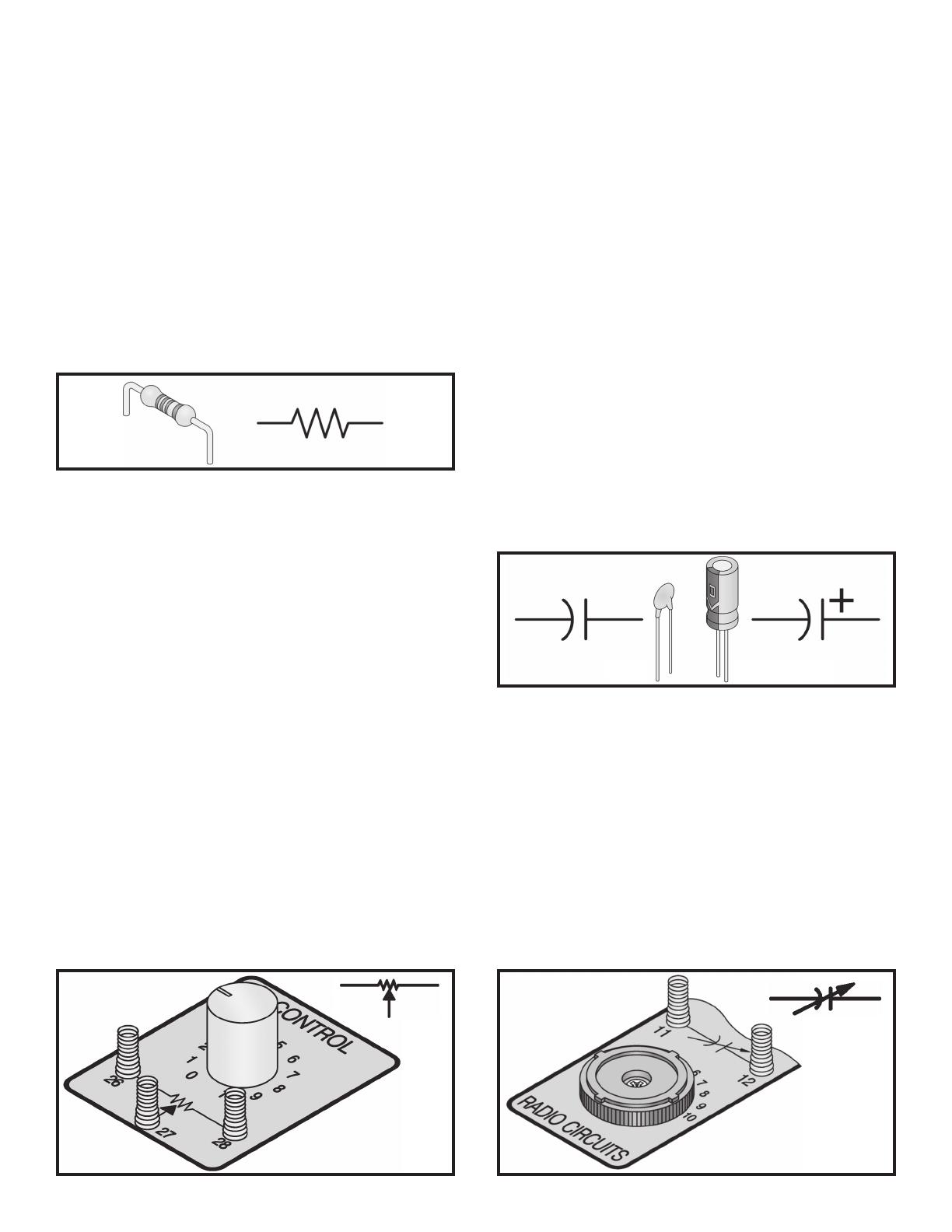
will be shown in a moment). Below the symbol for the
resistor is shown.
Resistor Color Code: The method for marking the
value of resistance on a part is by using colored
bands on each resistor. The representation of the
first ring is the digit of the value of the resistor. The
second ring is a representation of the second digit of
the resistors value. The third ring means that you to
which power of ten to multiply by, ( or the amount of
zeros to add). The fourth and final ring is a
representation of the construction tolerance. A
majority of resistors have a gold band that
represents 5% tolerance. Simply this means that the
resistor value is guaranteed to be 5% of the valued
marked. See the color chart on page 159.
Variable Resistor (Control): The variable resistor
is simply a control and this is required in many
electric circuits. The variable resistor can be used as
a light dimmer, volume control, and in many other
circuits when you are wanting to change resistance
easily and quickly. A normal resistor is shown, this
contains an additional arm contact that moves along
the resistive material and can tap off the resistance
desired.
Capacitors: Capacitors move alternating current
(AC) signals while prohibiting direct current (DC)
signals to pass. They store electricity and can
f
unction as filters to smooth out signals that pulsate.
Capacitors that are small are traditionally used in
high-frequency applications such as radios,
transmitters, or oscillators. Larger capacitors
ordinarily reserve electricity or act as filters. The
capacitance (capacity for storing electricity) of a
capacitor is expressed in a unit known as farad. An
extremely large amount of electricity defines the
farad. Most of the value of capacitors is
predetermined in millionths-of-a-farad or
microfarads.
Electrolytic - Electrolytic are the four largest
capacitors. They are marked with an “–”. There is
only one-way to connect them to the circuit, the +
and the – wires must always go into the correct
terminals.
Note - For safety, the electrolytic capacitors used in
the EP-130 are nonpolarized
type.
Disc - Unlike the electrolytic above, these capacitors
have no polarity and can be connected in either way.
Tuning Capacitor: Ever wonder what that knob that
changes the stations on your radio is? It’s a tuning
capacitor. When the knob is rotated, the capacitance
is changed. This alters the frequency of the circuit,
letting through only one frequency and blocking out
the rest.
-6-
Disc Electrolytic
EP-130_62315RevC.qxp_EP-130_062812 6/23/15 11:16 AM Page 6
Diodes: Are like one-way streets. They allow the
current to flow in only one direction. There are three
of these in your kit. Your kit contains one silicon diode
(
marked Si) as well as two germanium diodes
(marked Ge).
Transistors: Three transistors can be found in your
kit. The part that makes each transistor work is a tiny
chip, which is made of either germanium or silicon.
There are a total of three connections points on each
transistor. They are B, which stands for base, C,
which stands for collector, and E, which stands for
emitter. Mainly transistors are used to amplify weak
signals. Transistors can also be used as switches to
connect or disconnect other components as well as
oscillators to permit signals to flow in pulses.
LEDs (Light Emitting Diodes): These are special
diodes because they give off light whenever
electricity passes through them. (The current can
only pass through in one direction—similar to
“regular” diodes).
LED Digital Display: Seven Light Emitting Diodes
are arranged to create an outline that can show most
letters of the English alphabet and all the numbers.
An additional LED is added to represent a decimal
point.
The “8” LED display is mounted on a board and to
prevent burning out the display with excess current,
permanent resistors have been wired in.
Integrated Circuit: The transistor was invented in
the 1940’s and after that the next big break through
in electronics was in the 1960’s with the invention
integrated circuit or the ICs. The advantage of this
that the equivalent of hundreds or even thousands of
transistors, diodes and even resistors can be placed
into one small package.
Two types of ICs are used in this kit. They are the
quad two-input NAND and the dual-operational
amplifier, and you will have the chance to learn more
about these in a bit.
Simple ICs will help you to understand enough to
grasp the basic theories of more advanced ICs.
Cadmium Sulfide (CdS) Cell: This is what is known
as a semiconductor, which practically resists
electricity while it conducts. The resistance changes
by the amount of light that is shined upon it.
-7-
PNP
NPN
EP-130_62315RevC.qxp_EP-130_062812 6/23/15 11:16 AM Page 7
-8-
Antenna: This cylindrical component with a coil of
fine wire wrapped around it is a radio antenna. If
you’re wondering what the dark colored rod is, it’s
a
ctually mostly powdered iron. It’s also known as a
“Ferrite Core”, which is efficient for antennas, and
used in almost all transistor radios.
Transformer: Did you know that if you were to wrap
two wires from different circuits around different ends
of an iron bar, and if you were to add current in the
first circuit, it will magnetically create current in the
second circuit? That’s exactly what a transformer is!
Transformers are used to isolate parts of a circuit, to
keep them from interfering with each other.
If the iron bar in a transformer were allowed to rotate,
it would become a motor. However, if a magnet
within a coil is rotating then an electrical current is
made; this is called a generator. Those two ideas
may not seem important but they are the foundation
of the present society. Pretty much all of the
electricity used in this world is generated by huge
generators, which are propelled by water pressure or
steam. Wires transport energy to homes and
businesses where it will be used. Motors are used to
convert the electricity back into mechanical form so
that it can be used to drive machinery and
appliances.
Speaker: Did you know that electrical energy is
converted into sound through a speaker? By using the
energy from an AC electrical signal it creates
mechanical vibration. Sound waves, which are
created by variations of vibrations and then travel
a
cross the room. When you hear a sound it is actually
your ears feeling the pressure from the air vibrations.
To operate a speaker a high current and a low voltage
are needed, so the transformer will also be used with
the speaker. (A transformer can convert a high-
voltage/low current to a low-voltage/high current).
Similar to the speaker, is the earphone. It is movable
and more sensitive than the speaker, otherwise they
are the same. The earphone you will be using is
efficient as well as lightweight and can be used
without taking away too much electrical energy from
the circuit. Sound wise you will be using the
earphone for weak sounds and for louder sounds the
speaker will be used.
Batteries: The battery holders that are used in this
kit are constructed to hold six (6) “AA” batteries.
These batteries will be the supplier of all the power
used in your experiments. When you connect the
wires to the batteries make sure that you only
connect the batteries to terminals noted. Terminals
119 and 120 provide 3 volts while terminals 119 and
121 provide 4.5 volts. Be aware that parts can be
damaged (burned out) if you connect too much
voltage (you can get up to 9 volts from the
connections to the batteries) Be sure to make battery
connections the right way.
Caution: Make sure your wiring uses the correct
polarity (the “+” and “-” sides of the component)!
Some parts can be permanently damaged if you
reverse polarity.
EP-130_62315RevC.qxp_EP-130_062812 6/23/15 11:16 AM Page 8
-9-
Switch: You know what a switch is – you use
switches every day. When you slide (or flip) to the
proper position, the circuit will be completed,
allowing current to flow through. In the other position
a break is made, causing the circuit to be “off”. The
switch that we will be using is a double-pole, double-
throw switch. You will learn about that later on.
Key: The key is a simple switch—you press it and
electricity is allowed to flow through the circuit. When
you release it, the circuit is not complete because a
b
reak is caused in the circuit’s path. The key will be
used in most circuits often times in signaling circuits
(you can send Morse code this way as well as other
things).
Terminals:
Two terminals will be used in some
projects (terminals 13 and 14). They will be used to
make connections to external devices such as an
earphone, antenna or earth ground connection,
special sensor circuits and so forth.
Wires: Wires will be used to make connections to
the terminals.
Your parts and spring terminals are mounted on the
colorful platform. You can see how the wires are
connected to the parts and their terminals if you look
under the platform.
YOUR FIRST PROJECT
A simple wiring sequence is listed for each project.
Connect the wires with appropriate length between
each grouping of terminals listed. When doing the
experiment use the shortest wire that possibly gets
the job done. New groupings will be separated by a
comma, connect the terminals in each group.
As an example, here is the project 1 wiring
sequence:
1-29, 2-30, 3-104-106, 4-28-124, 5-41-105, 27-88,
75-87-103-40, 115-42-119, 76-116, 121-22.
Connect a wire between 1 and 29, another wire
between 2 and 30, another between 3 and 104 and
then another wire between 104 and 106. Continue
until all connections are made.
Caution: The last connection in each wiring
sequence is an important power wire; this is
deliberate. It is important that you make this
connection your LAST connection. Damage can
occur if one part of the circuit is completed before
another. Therefore follow the wiring sequence
exactly.
EP-130_62315RevC.qxp_EP-130_062812 6/23/15 11:16 AM Page 9
-10-
SUGGESTIONS TO HELP
Keep a Notebook
As you’re about to find out, you are going to learn
many things about electronics by using this kit. As
you learn, many of the things you discover in the
easy projects will be built upon in later projects. We
suggest using a notebook to help you organize the
data you will be collecting.
This notebook does not have to be like the one you
use in school. Think of it more as a fun notebook,
that way you can look back on the all the projects
you have done once you finish.
Wiring Sequence Marking
When you are wiring a project, especially those with
lots of connections, you will find it helpful to mark off
each terminal number as you connect the wires to it.
Use a pencil and make light marks so that you can
go back multiple times and re-read the sequence.
Collecting Components
You should start to make your own collection of
electronic parts and therefore have your own scrap
box of electronic parts. You can build your own
circuits in or on top of a framework, box or container.
You could use your circuit as a Science Fair project
at school and even make a major research project
from it.
TROUBLESHOOTING
You should have no problem with the projects
w
orking properly if you follow the wiring instructions.
However, if you do encounter a problem you can try
a
nd fix it by using the following troubleshooting
steps. These steps are comparable to those steps
that electronic technicians use to troubleshoot
complex electronic equipment.
1. Are the batteries being used new? If they are not,
this may be your problem because the batteries
could be too weak to power the project.
2. Is the project assembled properly? Check all the
wiring connections to make sure that you have all
the terminals wired correctly. Sometimes having
someone else look at it helps to find the problem.
3. Are you following the schematic diagram and the
e
xplanation of the circuit? As your understanding
and knowledge expands of electronics, you will be
a
ble to troubleshoot by following only a schematic,
and once you add the description of the circuit you
will be able to figure out your own problems.
4. If you have VOM, try taking some measurements
of the voltage and current. You might be surprised
just how handy a VOM really is.
5. Try building project 24 (Digital Display Circuit for
the Seven-Segment LED). This is a very simple
circuit that lights part of the LED display using only
2 wires.
Contact Elenco
®
if you still need help.
EP-130_62315RevC.qxp_EP-130_062812 6/23/15 11:16 AM Page 10
-11-
I. PLAYGROUND OF ELECTRONIC CIRCUITS
EP-130_62315RevC.qxp_EP-130_062812 6/23/15 11:16 AM Page 11
-12-
For your first experiment you are going to make a
c
ircuit that sounds like a woodpecker chirping.
F
ollow the wiring sequence carefully and observe
the drawings. Don’t forget to make all the proper
connections and have fun!
The simple circuit shown here does not have a key
or a switch, but you can easily add one. Replace
connection 124-28 with connections 124-137 and
138-28 to connect the key. Or, you can hook the
switch up by replacing 124-28 with connections
124-131 and 132-28. Now you can easily turn off
and on the circuit. Go outside and see if you can
attract birds with it.
Want a different sound? Try varied combinations of
capacitance and resistance in place of the 100mF
capacitor and the 1kW resistor. To change the
100mF capacitor to 470µF, disconnect terminal 116
and transfer to terminal 118. Then, reconnect the
wire from 115 to connect to 117. Your “bird” might
sound like a cricket, or a bear!
Also, you can try using the 3V power supply.
Disconnect terminal 119 and connect it to terminal
123. Now your bird might sound like an English
sparrow. Feel free to experiment. Just don’t replace
the 47kW resistor with anything below 10kW,
because it might damage the transistor.
Notes:
EXPERIMENT #1: WOODPECKER
Wiring Sequence:
o 1-29
o 2-30
o 3-104-106
o 4-28-124
o 5-41-105
o 27-88
o 75-87-103-40
o 115-42-119
o 76-116
o 121-122
Schematic
EP-130_62315RevC.qxp_EP-130_062812 6/23/15 11:16 AM Page 12
-13-
H
ere is the first siren you are going to do – don’t be
shocked if this experiment becomes the most
famous circuit in this kit.
This siren sounds like a real siren on a police car!
After the wiring is competed press the key. The tone
you eventually hear gets higher after pressing the
key. When you release the key, the tone gets lower
and then fades out.
Try some of these modifications:
1. If you change the 10mF capacitor to a 100mF or a
470mF it will give a very long delay for both turn
off and turn on.
2. Change the circuit to remove the delays by
temporarily disconnecting the 10mF capacitor.
3. Change out the 0.02mF capacitor to a 0.01mF
capacitor, and then to a 0.05mF capacitor.
N
otes:
EXPERIMENT #2: POLICE SIREN
Wiring Sequence:
o 1-29
o 2-30
o 3-103-109
o 4-119-137
o 5-47-110
o 46-104-90
o 114-48-120
o 85-138
o 86-89-113
Schematic
EP-130_62315RevC.qxp_EP-130_062812 6/23/15 11:16 AM Page 13
-14-
L
earning to play a musical instrument? Then you
might find this experiment helpful. This is an
electronic version of the metronome, used by
m
usical students and musical geniuses alike,
worldwide.
If you press the key, you hear a repeating sound
from the speaker. Turn the control knob to the right
and you’ll hear the sound “get faster” as the time
between sounds shortens.
Try swapping out the 4.7kW resistor with different
one. Also, you might want to try a different capacitor
in place of the 100mF capacitor too see what effect
it will have. Are you still keeping notes?
If you would like to hear the difference that a
stronger capacitor makes, try connecting the 470mF
capacitor to the batteries. Connect terminal 117 to
119 and terminal 118 to terminal 120. You might
need to adjust the control to maintain the same
pulse rate.
N
otes:
EXPERIMENT #3: METRONOME
Wiring Sequence:
o 1-29
o 2-30
o 3-104-116
o 4-28-138
o 5-41-103
o 27-80
o 40-115-79
o 42-119
o 120-137
Schematic
EP-130_62315RevC.qxp_EP-130_062812 6/23/15 11:16 AM Page 14
-15-
D
oes your home lack a grandfather clock? Well not
any longer, with this experiment you will make your
own electronic grandfather clock.
This circuit will produce clicks at approximately one-
second intervals. The sound and timing together
might remind you of an old grandfather clock. If you
would like for it to go faster or slower then you can
change out the 100kW resistor.
The steady ticking can put animals (and people) into
a sleepy state of mind. If you have ever traveled on
a train, you remember how sleepy you get from
hearing the clicking sound of the wheels.
Ever scare a clock out of ticking? Shout directly into
the speaker. You can briefly stop the clock! The
speaker acts like a microphone as well. The sound
of your voice vibrates the speaker and disturbs the
electrical balance of the circuit, briefly.
N
otes:
EXPERIMENT #4: GRANDFATHER CLOCK
Wiring Sequence:
o 1-29
o 2-30
o 3-104-116
o 4-90-120
o 5-41-103
o 40-72
o 42-119
o 71-89-115
Schematic
EP-130_62315RevC.qxp_EP-130_062812 6/23/15 11:16 AM Page 15
-16-
H
ave you ever wanted to make music just by
waving your hand? Well that is just what you are
going to be doing. How does this magic work? Well,
t
he tones change based upon the amount of light
that gets to the CdS cell. With a bright light the tone
is higher but, if you cover the CdS with your hand,
the sound gets lower.
Since the early days of vacuum-tube circuitry, this
method of creating musical sound has been used.
Leon Theremin was the inventor of this type of
instrument, thus the instrument has been named
the Theremin in his honor.
After the wiring has been completed press the key
and then wave your hand over the CdS cell. You will
soon be able to play music with this magical
electronic instrument after just a bit of practice. Most
importantly HAVE FUN!
N
otes:
EXPERIMENT #5: HARP
Wiring Sequence:
o 1-29
o 2-30
o 3-16-41-109
o 4-120
o 5-106-110
o 15-87
o 40-105-88
o 42-137
o 119-138
Schematic
EP-130_62315RevC.qxp_EP-130_062812 6/23/15 11:16 AM Page 16
-17-
In this experiment you are going to make a circuit
t
hat sounds like the mockingbird.
Follow the wiring sequence and observe the
drawings. Don’t forget to make all the proper
connections and have fun!
To finish the circuit below, slide the switch to the A
position to turn on the power. No sound will come
from the speakers yet. When you press the key you
will hear a sound quite like a bird singing from the
speaker. When you release the key, you will still be
able to hear the chirping sound but eventually it will
slow down and stop. The first transistor “Q1” is
dropped off from the battery when the key is
released. Transistor “Q2” still produces the bird
sound until the controlling current from transistor
“Q1” stops.
Try using a different value capacitor instead of the
10mF and the 100mF capacitors. These capacitors
control the amount of electricity reaching the
transistors. Listen for the difference. Make sure to
start keeping notes on your experiments.
Notes:
EXPERIMENT #6: TWEETING BIRD
Wiring Sequence:
o 1-29
o 2-30
o 3-106-110
o 4-41-131-138
o 5-44-109
o 40-114-91-75
o 42-85
o 43-105-86-77
o 119-45-115-113-92
o 76-137
o 78-116
o 120-132
Schematic
EP-130_62315RevC.qxp_EP-130_062812 6/23/15 11:16 AM Page 17
-18-
A
re you bothered by mice, do you not have a
mousetrap? You should try this next experiment to
help you instead—see if the sound of this cat can
k
eep the pests out of your life.
Just follow the drawing below and the wiring
sequence. To start the experiment switch the set to
B. Press down on the key and release it
immediately. You will hear the meow from the cat
coming from the speaker. If you adjust the control
knob while the cat’s meow is fading away, what
effect on the circuit operation does it have? Now set
the switch to A and try it once more. Now it sounds
as if the cat is begging for a dish of milk in a low,
long sounding tone.
To produce a variety of sounds try experimenting
with this circuit. Whatever you do just don’t change
the value of the 0.05mF capacitor to more than 10mF
or reduce the value of the 10kW resistor— or else
the transistor could get damaged.
N
otes:
EXPERIMENT #7: MEOWING CAT
Wiring Sequence:
o 1-29
o 2-30
o 3-41-109
o 4-72-82-132-114
o 5-106-110
o 27-40-105
o 115-113-42-119
o 71-138
o 81-28
o 116-131
o 120-137
Schematic
EP-130_62315RevC.qxp_EP-130_062812 6/23/15 11:16 AM Page 18
-19-
D
id you know that many marine animals
communicate to each other using sound? I bet you
have heard that dolphins and whales use sound for
c
ommunication, but what you probably don’t know
is that they are not the only ones. Due to research
we are able to find out that some fish are attracted
to certain sounds. Making this circuit, will allow you
do to some research of your own.
Once you make the last connection you are turning
on the power. You should be able to hear pulses of
sound coming from the speaker. The sound
changes by turning the control. This circuit is a type
of audio oscillator circuit, which you will learn more
about later in this book.
If you have a fish tank at home or at school you
should place your kit near the glass to see if the fish
are attracted to the sound. Are they?
If you like to fish, you should try this out while
fishing. What you need to do is attach another
speaker to terminals 1 and 2 using long lengths of
insulated wire. Wrap the speaker carefully in a
waterproof plastic bag or place it in a tightly sealed
jar. Make sure that no water is able to reach the
speaker. Lower the speaker into the water, cast your
fishing line, and see if you catch anything.
N
otes:
EXPERIMENT #8: CALLING’ FISH
Wiring Sequence:
o 1-29
o 2-30
o 3-93-100-110
o 4-120
o 5-41-109
o 27-94
o 28-40-99
o 42-119
Schematic
EP-130_62315RevC.qxp_EP-130_062812 6/23/15 11:16 AM Page 19
-20-
I
n this experiment you will be creating an oscillator
circuit that doesn’t make sound using a speaker or
an earphone. Instead the circuit will produce light
w
ith an LED. This will give you an idea of how
larger strobe lights work. When you press the key,
watch LED 1. At certain intervals the light turns on
and off. With the 50kW control you can control the
rate of blinking.
Try substituting a capacitor with a lower value for
the 100mF capacitor to see how an oscillator works.
Make a prediction about what you think will
happen? Were you correct?
N
otes:
EXPERIMENT #9: STROBE LIGHT
Wiring Sequence:
o 3-115
o 4-27-138
o 5-31
o 28-80
o 33-47
o 79-116-112-46
o 111-48-121
o 119-137
Schematic
EP-130_62315RevC.qxp_EP-130_062812 6/23/15 11:16 AM Page 20
  • Page 1 1
  • Page 2 2
  • Page 3 3
  • Page 4 4
  • Page 5 5
  • Page 6 6
  • Page 7 7
  • Page 8 8
  • Page 9 9
  • Page 10 10
  • Page 11 11
  • Page 12 12
  • Page 13 13
  • Page 14 14
  • Page 15 15
  • Page 16 16
  • Page 17 17
  • Page 18 18
  • Page 19 19
  • Page 20 20
  • Page 21 21
  • Page 22 22
  • Page 23 23
  • Page 24 24
  • Page 25 25
  • Page 26 26
  • Page 27 27
  • Page 28 28
  • Page 29 29
  • Page 30 30
  • Page 31 31
  • Page 32 32
  • Page 33 33
  • Page 34 34
  • Page 35 35
  • Page 36 36
  • Page 37 37
  • Page 38 38
  • Page 39 39
  • Page 40 40
  • Page 41 41
  • Page 42 42
  • Page 43 43
  • Page 44 44
  • Page 45 45
  • Page 46 46
  • Page 47 47
  • Page 48 48
  • Page 49 49
  • Page 50 50
  • Page 51 51
  • Page 52 52
  • Page 53 53
  • Page 54 54
  • Page 55 55
  • Page 56 56
  • Page 57 57
  • Page 58 58
  • Page 59 59
  • Page 60 60
  • Page 61 61
  • Page 62 62
  • Page 63 63
  • Page 64 64
  • Page 65 65
  • Page 66 66
  • Page 67 67
  • Page 68 68
  • Page 69 69
  • Page 70 70
  • Page 71 71
  • Page 72 72
  • Page 73 73
  • Page 74 74
  • Page 75 75
  • Page 76 76
  • Page 77 77
  • Page 78 78
  • Page 79 79
  • Page 80 80
  • Page 81 81
  • Page 82 82
  • Page 83 83
  • Page 84 84
  • Page 85 85
  • Page 86 86
  • Page 87 87
  • Page 88 88
  • Page 89 89
  • Page 90 90
  • Page 91 91
  • Page 92 92
  • Page 93 93
  • Page 94 94
  • Page 95 95
  • Page 96 96
  • Page 97 97
  • Page 98 98
  • Page 99 99
  • Page 100 100
  • Page 101 101
  • Page 102 102
  • Page 103 103
  • Page 104 104
  • Page 105 105
  • Page 106 106
  • Page 107 107
  • Page 108 108
  • Page 109 109
  • Page 110 110
  • Page 111 111
  • Page 112 112
  • Page 113 113
  • Page 114 114
  • Page 115 115
  • Page 116 116
  • Page 117 117
  • Page 118 118
  • Page 119 119
  • Page 120 120
  • Page 121 121
  • Page 122 122
  • Page 123 123
  • Page 124 124
  • Page 125 125
  • Page 126 126
  • Page 127 127
  • Page 128 128
  • Page 129 129
  • Page 130 130
  • Page 131 131
  • Page 132 132
  • Page 133 133
  • Page 134 134
  • Page 135 135
  • Page 136 136
  • Page 137 137
  • Page 138 138
  • Page 139 139
  • Page 140 140
  • Page 141 141
  • Page 142 142
  • Page 143 143
  • Page 144 144
  • Page 145 145
  • Page 146 146
  • Page 147 147
  • Page 148 148
  • Page 149 149
  • Page 150 150
  • Page 151 151
  • Page 152 152
  • Page 153 153
  • Page 154 154
  • Page 155 155
  • Page 156 156
  • Page 157 157
  • Page 158 158
  • Page 159 159
  • Page 160 160

Elenco EP130 Owner's manual

Type
Owner's manual

Ask a question and I''ll find the answer in the document

Finding information in a document is now easier with AI