Allied Telesis AlliedWare Plus AT-GS980M/52 Installation guide
- Category
- Network switches
- Type
- Installation guide
This manual is also suitable for

613-002638 Rev. B
GS980M Series
Gigabit Ethernet Switches
AlliedWare Plus™
AT-GS980M/52
AT-GS980M/52PS
Installation Guide

Copyright 2019 Allied Telesis, Inc.
All rights reserved. No part of this publication may be reproduced without prior written permission from Allied Telesis, Inc.
Allied Telesis, VCStack, and the Allied Telesis logo are trademarks of Allied Telesis, Incorporated. All other product names, company
names, logos or other designations mentioned herein are trademarks or registered trademarks of their respective owners.
Allied Telesis, Inc. reserves the right to make changes in specifications and other information contained in this document without prior
written notice. The information provided herein is subject to change without notice. In no event shall Allied Telesis, Inc. be liable for
any incidental, special, indirect, or consequential damages whatsoever, including but not limited to lost profits, arising out of or related
to this manual or the information contained herein, even if Allied Telesis, Inc. has been advised of, known, or should have known, the
possibility of such damages.

3
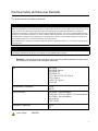
Electrical Safety and Emissions Standards
This product meets the following standards.
U.S. Federal Communications Commission
Radiated Energy
Note: This equipment has been tested and found to comply with the limits for a Class A digital device pursuant to Part 15
of FCC Rules. These limits are designed to provide reasonable protection against harmful interference when the
equipment is operated in a commercial environment. This equipment generates, uses, and can radiate radio frequency
energy and, if not installed and used in accordance with this instruction manual, may cause harmful interference to radio
communications. Operation of this equipment in a residential area is likely to cause harmful interference in which case
the user will be required to correct the interference at his own expense.
Note: Modifications or changes not expressly approved of by the manufacturer or the FCC, can void your right to operate
this equipment.
Industry Canada
This Class A digital apparatus complies with Canadian ICES-003.
Cet appareil numérique de la classe A est conforme à la norme NMB-003 du Canada.
Warning: In a domestic environment this product may cause radio interference in which case
the user may be required to take adequate measures.
EMC EN 55024
EN 55032 Class A
EN 61000-3-2
EN 61000-3-3
FCC Part 15 (CFR 47) Class A
VCCI Class A
CISPR 22 Class A
ICES-003
Environmental Compliance RoHS
WEEE
Electrical Safety EN 60950-1 (second edition)
CAN/CSA-C22.2 No. 60950-1-07 (second edition)
UL 60950-1 (second edition)
cULus Mark
TUV-T-Mark
Regulatory Compliance RCM
CE
Laser Safety EN60825

4
Translated Safety Statements
Important: Safety statements that have the symbol are translated into multiple languages in the
Translated Safety Statements document at www.alliedtelesis.com/library.
Remarque: Les consignes de sécurité portant le symbole sont traduites dans plusieurs langues
dans le document Translated Safety Statements, disponible à l'adresse www.alliedtelesis.com/
library

5
Preface ...............................................................................................................................................................................11
Document Conventions .......................................................................................................................................................12
Contacting Allied Telesis .....................................................................................................................................................13
Chapter 1: Overview ........................................................................................................................................................ 15
Front and Rear Panels ........................................................................................................................................................16
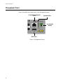
Management Panel .............................................................................................................................................................18
Features ..............................................................................................................................................................................19
GS980M Models...........................................................................................................................................................19
10/100/1000Mbps Twisted Pair Ports ..........................................................................................................................19
100Mbps or 1Gbps SFP Transceiver Ports..................................................................................................................19
Power Over Ethernet....................................................................................................................................................20
LEDs.............................................................................................................................................................................20
Installation Options.......................................................................................................................................................20
Management Software and Interfaces .........................................................................................................................20
Console Port.................................................................................................................................................................20
USB Port ......................................................................................................................................................................21
Management Methods..................................................................................................................................................21
Power Conservation.....................................................................................................................................................21
MAC Address Table .....................................................................................................................................................21
10/100/1000Mbps Twisted Pair Ports..................................................................................................................................22
Connector Type............................................................................................................................................................22
Speed...........................................................................................................................................................................22
Duplex Mode................................................................................................................................................................22
Maximum Distance.......................................................................................................................................................22
Cable Requirements.....................................................................................................................................................22
Automatic MDIX Detection ...........................................................................................................................................23
LEDs.............................................................................................................................................................................23
Power Over Ethernet on the AT-GS980M/52PS Switch......................................................................................................26
PoE Standards.............................................................................................................................................................26
Powered Device Classes .............................................................................................................................................26
Power Budget...............................................................................................................................................................27
Port Priorities................................................................................................................................................................27
Wiring Implementation..................................................................................................................................................28
SFP Transceiver Ports.........................................................................................................................................................29
SFP Transceivers.........................................................................................................................................................29
LEDs.............................................................................................................................................................................29
Fault and Power LEDs.........................................................................................................................................................31
eco-friendly Button...............................................................................................................................................................32
USB Port..............................................................................................................................................................................33
USB Port LED ..............................................................................................................................................................33
Console Port........................................................................................................................................................................34
Power Supply and Fan ........................................................................................................................................................35
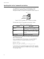
Specifying Ports in the Command Line Interface.................................................................................................................36
Chapter 2: Beginning the Installation ............................................................................................................................37
Reviewing Safety Precautions.............................................................................................................................................38
Installation Options..............................................................................................................................................................42
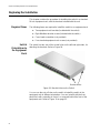
Choosing a Site for the Switch ............................................................................................................................................43
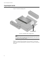
Unpacking the Switch..........................................................................................................................................................44
Contents

Contents
6
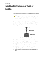
Chapter 3: Installing the Switch on a Table or Desktop ...............................................................................................47
Chapter 4: Installing the Switch in an Equipment Rack ...............................................................................................51
Beginning the Installation.................................................................................................................................................... 52
Required Items............................................................................................................................................................ 52
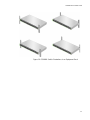
Switch Orientations in the Equipment Rack................................................................................................................. 52
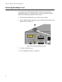
Removing the Bumper Feet................................................................................................................................................ 54
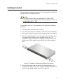
Installing the Switch............................................................................................................................................................ 55
Chapter 5: Installing the Switch on a Wall .....................................................................................................................57
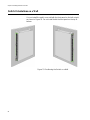
Switch Orientations on a Wall............................................................................................................................................. 58
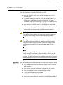
Installation Guidelines......................................................................................................................................................... 59
Tools and Material....................................................................................................................................................... 59
Plywood Base..................................................................................................................................................................... 61
Installing a Plywood Base................................................................................................................................................... 63
Installing the Switch on a Plywood Base ............................................................................................................................ 64
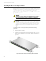
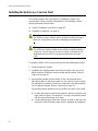
Installing the Switch on a Concrete Wall............................................................................................................................. 66
Chapter 6: Cabling the Networking Ports and Powering On the Switch ....................................................................69
Cabling Twisted Pair Ports.................................................................................................................................................. 70
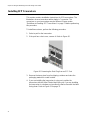
Guidelines to Handling SFP Transceivers.......................................................................................................................... 71
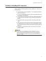
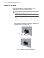
Installing SFP Transceivers................................................................................................................................................ 72
Powering On the Switch...................................................................................................................................................... 76
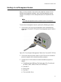
Starting a Local Management Session............................................................................................................................... 79
Verifying the Switch with AlliedWare Plus Commands....................................................................................................... 81
Chapter 7: Troubleshooting
............................................................................................................................................83
Appendix A: Technical Specifications ...........................................................................................................................87
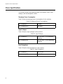
Physical Specifications ....................................................................................................................................................... 88
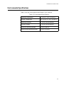
Environmental Specifications.............................................................................................................................................. 89
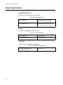
Power Specifications........................................................................................................................................................... 90
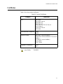
Certificates.......................................................................................................................................................................... 91
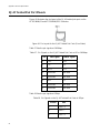
RJ-45 Twisted Pair Port Pinouts......................................................................................................................................... 92
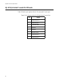
RJ-45 Style Serial Console Port Pinouts ............................................................................................................................ 94

7
Figure 1: Front Panels of the GS980M Series Switches ......................................................................................................16
Figure 2: Back Panels ..........................................................................................................................................................17
Figure 3: Management Panel ...............................................................................................................................................18
Figure 4: LEDs for the Twisted Pair Ports on the AT-GS980M/52 Switch............................................................................23
Figure 5: LEDs for the Twisted Pair Ports on the AT-GS980M/52PS Switch.......................................................................24
Figure 6: SFP Transceiver Port LEDs ..................................................................................................................................29
Figure 7: Fault and Power LEDs...........................................................................................................................................31
Figure 8: eco-friendly Button ................................................................................................................................................32
Figure 9: USB Port and LED ................................................................................................................................................33
Figure 10: PORT Parameter in the Command Line Interface...............................................................................................36
Figure 11: Installation Options..............................................................................................................................................42
Figure 12: GS980M Switch Shipping Box.............................................................................................................................44
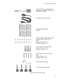
Figure 13: Accessory Kit Items.............................................................................................................................................45
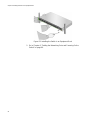
Figure 14: Parts of the Bumper Feet....................................................................................................................................47
Figure 15: Inset the Rivet Housing into the Bumper Foot.....................................................................................................48
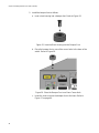
Figure 16: Place the Bumper Foot on a Base Corner Hole..................................................................................................48
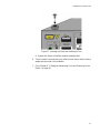
Figure 17: Inserting the Rivet into the Bumper Foot.............................................................................................................49
Figure 18: Bracket Holes on the Switch................................................................................................................................52
Figure 19: GS980M Switch Orientations in an Equipment Rack..........................................................................................53
Figure 20: Removing the Bumper Feet.................................................................................................................................54
Figure 21: Example of Attaching the Brackets to the Switch................................................................................................55
Figure 22: Installing the Switch in an Equipment Rack.........................................................................................................56
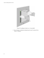
Figure 23: Positioning the Switch on a Wall .........................................................................................................................58
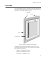
Figure 24: Switch on a Wall with a Plywood Base................................................................................................................61
Figure 25: Steps to Installing the Switch with a Plywood Base ............................................................................................62
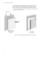
Figure 26: Bracket Positions for Installing Switch on a Wall.................................................................................................64
Figure 27: Securing the Switch to the Plywood Base.............................................................................
..............................65
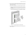
Figure 28: Marking the Locations of the Bracket Holes on a Concrete Wall ........................................................................67
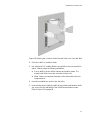
Figure 29: Installing the Switch on a Concrete Wall.............................................................................................................68
Figure 30: Removing the Dust Plug from an SFP Port.........................................................................................................72
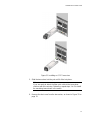
Figure 31: Installing an SFP Transceiver..............................................................................................................................73
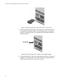
Figure 32: Removing the Dust Cover from an SFP Transceiver ..........................................................................................74
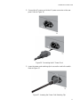
Figure 33: Positioning the SFP Handle in the Upright Position ............................................................................................74
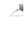
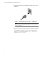
Figure 34: Connecting a Fiber Optic Cable to an SFP Transceiver......................................................................................75
Figure 35: Installing the Power Cord Retaining Clip.............................................................................................................76
Figure 36: Connecting the AC Power Cord ..........................................................................................................................77
Figure 37: Lowering the Power Cord Retaining Clip.............................................................................................................77
Figure 38: Connecting the Power Cord to an AC Power Source..........................................................................................78
Figure 39: Connecting the Management Cable to the Console RS-232 Port.......................................................................79
Figure 40: User Exec Mode Prompt .....................................................................................................................................80
Figure 41: Pin Layout for the RJ-45 Twisted Pair Ports (Front View)...................................................................................92
Figures

Figures
8

9
Tables
Table 1: Basic Features .......................................................................................................................................................19
Table 2: LEDS for the Twisted Pair Ports on the AT-GS980M/52 Switch ...........................................................................23
Table 3: LEDs for the Twisted Pair Ports on the AT-GS980M/52PS Switch .......................................................................25
Table 4: IEEE Powered Device Classes ..............................................................................................................................26
Table 5: LEDS for the SFP Transceiver Ports .....................................................................................................................29
Table 6: Fault and Power LEDS ..........................................................................................................................................31
Table 7: USB LED ...............................................................................................................................................................33
Table 8: PORT Parameter Format .......................................................................................................................................36
Table 9: Product Dimensions ...............................................................................................................................................88
Table 10: Product Weights ..................................................................................................................................................88
Table 11: Ventilation Requirements .....................................................................................................................................88
Table 12: Environmental Specifications ...............................................................................................................................89
Table 13: Maximum Power Consumptions ..........................................................................................................................90
Table 14: Input Voltages ......................................................................................................................................................90
Table 15: Heat Dissipations .................................................................................................................................................90
Table 16: Product Certificates .............................................................................................................................................91
Table 17: Pin Signals on the RJ-45 Twisted Pair Ports at 10 or 100Mbps .........................................................................92
Table 18: Pin Signals on the RJ-45 Twisted Pair Ports at 1Gbps .......................................................................................92
Table 19: Pin Signals of the RJ-45 Style Serial Console Port .............................................................................................94

Tables
10


Preface
12
Document Conventions
This document uses the following conventions:
Note
Notes provide additional information.
Caution
Cautions inform you that performing or omitting a specific action
may result in equipment damage or loss of data.
Warning
Warnings inform you that performing or omitting a specific action
may result in bodily injury.

GS980M Series Installation Guide
13
Contacting Allied Telesis
If you need assistance with this product, you can contact Allied Telesis
technical support by going to the Support & Services section of the Allied
Telesis web site at www.alliedtelesis.com/support. You can find links for
the following services on this page:
24/7 Online Support — Enter our interactive support center to
search for answers to your product questions in our knowledge
database, to check support tickets, to learn about RMAs, and to
contact Allied Telesis technical experts.
USA and EMEA phone support — Select the phone number that
best fits your location and customer type.
Hardware warranty information — Learn about Allied Telesis
warranties and register your product online.
Replacement Services — Submit a Return Merchandise
Authorization (RMA) request via our interactive support center.
Documentation — View the most recent installation and user
guides, software release notes, white papers, and data sheets for
your products.
Software Downloads — Download the latest software releases for
your managed products.
For sales or corporate information, go to www.alliedtelesis.com/contact
and select your region.

Preface
14

15
Chapter 1
Overview
This chapter contains the following sections:
“Front and Rear Panels” on page 16
“Management Panel” on page 18
“Features” on page 19
“10/100/1000Mbps Twisted Pair Ports” on page 22
“Power Over Ethernet on the AT-GS980M/52PS Switch” on page 26
“SFP Transceiver Ports” on page 29
“Fault and Power LEDs” on page 31
“eco-friendly Button” on page 32
“USB Port” on page 33
“Console Port” on page 34
“Power Supply and Fan” on page 35
“Specifying Ports in the Command Line Interface” on page 36

Chapter 1: Overview
16
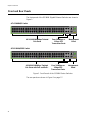
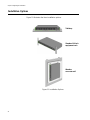
Front and Rear Panels
The front panels of the GS980M Gigabit Ethernet Switches are shown in
Figure 1.
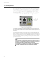
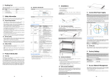
Figure 1. Front Panels of the GS980M Series Switches
The rear panels are shown in Figure 2 on page 17.
AT-GS980M/52PS Switch
48 10/100/1000Mbps Twisted
Pair Ports
Management
Panel
AT-GS980M/52 Switch
Four 100Mbps or
1Gbps SFP
Transceiver Ports
48 10/100/1000Mbps Twisted
Pair Ports with PoE and PoE+
Management
Panel
Four 100Mbps or
1Gbps SFP
Transceiver Ports

GS980M Series Installation Guide
17
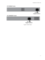
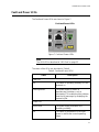
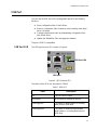
Figure 2. Back Panels
AC Power
Supply Connector
AT-GS980M/52PS Switch
AT-GS980M/52 Switch
AC Power
Supply Connector


GS980M Series Installation Guide
19
Features
The following sections review the hardware features of the Gigabit
Ethernet switches in the GS980M Series.
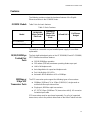
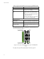
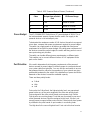
GS980M Models Table 1 lists the basic features.
The switches come with one pre-installed power supply. It is not field-
replaceable.
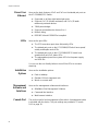
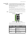
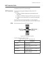
10/100/1000Mbps
Twisted Pair
Ports
The forty eight twisted pair ports on the AT-GS980M/52 and AT-GS980M/
52PS Switches have these features:
10/100/1000Mbps operation
100 meters (328 feet) maximum operating distance per port
Half or full-duplex mode
Auto-Negotiation for speed and duplex mode
Port Link/Activity (L/A) LEDs
Automatic MDIX detection at 10 or 100Mbps.
100Mbps or
1Gbps SFP
Transceiver Ports
The SFP transceiver ports support the following types of transceivers:
100Mbps (100Base-FX) or 1Gbps (1000SX/LX) single-mode or
multi-mode fiber optic transceivers
Single-port, BiDi fiber optic transceivers
AT-SPTX 1Gbps (1000Base-TX) transceiver with RJ-45 connector
for twisted pair cable
SFP transceivers must be purchased separately. For a list of supported
transceivers, refer to the product data sheet on the Allied Telesis web site.
Table 1. Basic Features
Model
10/100/1000
Mbps Twisted
Pair Ports
100Mbps or
1Gbps SFP
Transceiver
Ports
PoE and PoE+
PoE Power
Budget
AT-GS980M/52 48 4 No -
AT-GS980M/52PS 48 4 Yes 740W

Chapter 1: Overview
20
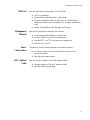
Power Over
Ethernet
Here are the basic features of PoE and PoE+ on the twisted pair ports on
the AT-GS980M/52PS Switch:
Supported on all forty eight twisted pair ports
Supports PoE (15.4 watts maximum) and PoE+ (30 watts
maximum) powered devices
740W power budget
Supports powered device classes 0 to 4
Mode A wiring
IEEE802.3af and IEEE802.3at compliant
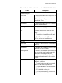
LEDs Here are the port LEDs:
The SFP transceiver ports have link/activity LEDs.
The twisted pair ports on the AT-GS980M/52 Switch have speed/
activity and duplex mode LEDs.
The twisted pair ports on the AT-GS980M/52PS Switch have
speed/activity and PoE status LEDs.
The management panel has system LEDs for the power supply
and USB slot.
You can use the eco-friendly button to turn off the LEDs to conserve
electricity.
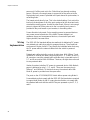
Installation
Options
Here are the installation options:
Desk or tabletop
Standard 19-inch equipment rack
Wood or concrete wall
Management
Software and
Interfaces
Here are the management software and interfaces:
AlliedWare Plus Management Software
Command line interface
Web browser interface
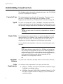
Console Port The port is used for local management of the switch. A management cable
is provided with the device. The port settings are provided in “Console
Port” on page 34.
Page is loading ...
Page is loading ...
Page is loading ...
Page is loading ...
Page is loading ...
Page is loading ...
Page is loading ...
Page is loading ...
Page is loading ...
Page is loading ...
Page is loading ...
Page is loading ...
Page is loading ...
Page is loading ...
Page is loading ...
Page is loading ...
Page is loading ...
Page is loading ...
Page is loading ...
Page is loading ...
Page is loading ...
Page is loading ...
Page is loading ...
Page is loading ...
Page is loading ...
Page is loading ...
Page is loading ...
Page is loading ...
Page is loading ...
Page is loading ...
Page is loading ...
Page is loading ...
Page is loading ...
Page is loading ...
Page is loading ...
Page is loading ...
Page is loading ...
Page is loading ...
Page is loading ...
Page is loading ...
Page is loading ...
Page is loading ...
Page is loading ...
Page is loading ...
Page is loading ...
Page is loading ...
Page is loading ...
Page is loading ...
Page is loading ...
Page is loading ...
Page is loading ...
Page is loading ...
Page is loading ...
Page is loading ...
Page is loading ...
Page is loading ...
Page is loading ...
Page is loading ...
Page is loading ...
Page is loading ...
Page is loading ...
Page is loading ...
Page is loading ...
Page is loading ...
Page is loading ...
Page is loading ...
Page is loading ...
Page is loading ...
Page is loading ...
Page is loading ...
Page is loading ...
Page is loading ...
Page is loading ...
Page is loading ...
-
 1
1
-
 2
2
-
 3
3
-
 4
4
-
 5
5
-
 6
6
-
 7
7
-
 8
8
-
 9
9
-
 10
10
-
 11
11
-
 12
12
-
 13
13
-
 14
14
-
 15
15
-
 16
16
-
 17
17
-
 18
18
-
 19
19
-
 20
20
-
 21
21
-
 22
22
-
 23
23
-
 24
24
-
 25
25
-
 26
26
-
 27
27
-
 28
28
-
 29
29
-
 30
30
-
 31
31
-
 32
32
-
 33
33
-
 34
34
-
 35
35
-
 36
36
-
 37
37
-
 38
38
-
 39
39
-
 40
40
-
 41
41
-
 42
42
-
 43
43
-
 44
44
-
 45
45
-
 46
46
-
 47
47
-
 48
48
-
 49
49
-
 50
50
-
 51
51
-
 52
52
-
 53
53
-
 54
54
-
 55
55
-
 56
56
-
 57
57
-
 58
58
-
 59
59
-
 60
60
-
 61
61
-
 62
62
-
 63
63
-
 64
64
-
 65
65
-
 66
66
-
 67
67
-
 68
68
-
 69
69
-
 70
70
-
 71
71
-
 72
72
-
 73
73
-
 74
74
-
 75
75
-
 76
76
-
 77
77
-
 78
78
-
 79
79
-
 80
80
-
 81
81
-
 82
82
-
 83
83
-
 84
84
-
 85
85
-
 86
86
-
 87
87
-
 88
88
-
 89
89
-
 90
90
-
 91
91
-
 92
92
-
 93
93
-
 94
94


Allied Telesis AlliedWare Plus AT-GS980M/52 Installation guide
- Category
- Network switches
- Type
- Installation guide
- This manual is also suitable for
Ask a question and I''ll find the answer in the document
Finding information in a document is now easier with AI
Related papers
-
Allied Telesis AT-GS924M Installation guide
-
-
-
-
-
-
-
-
-
Other documents
-
Eminent EM4405 Datasheet
-
Repotec RP-PG1526H Owner's manual
-
 UTEPO UPDS3101-PDA User manual
-
Comtrend ES-7201PoE User guide
-
 UTEPO UTP3310TS-PSB-L2 User manual
-
-
-
Trendnet RB-TPE-5240WS User guide
-
Trendnet TPE-1620WSF User guide
-
Netgear GS305P Installation guide

