Troy-Bilt Log Splitter LS338 User manual
- Category
- Log splitters
- Type
- User manual
This manual is also suitable for

!®
Operator's Manual
Log Splitter
Model LS338
IMPORTANT: Read safety rules and instructions carefully before operating equipment.
Warning: This unit is equipped with an internal combustion engine and should not be used on or near any unimproved forest-
covered, brush-covered or grass-covered land unless the engine's exhaust system is equipped with a spark arrester meeting
applicable local or state laws (if any). If a spark arrester is used, it should be maintained in effective working order by the operator.
In the State of California the above is required by law (Section 4442 of the California Public Resources Code). Other states may have
similar laws. Federal laws apply on federal lands. A spark arrester for the muffler is available through your nearest engine authorized
service dealer or contact the service department, P.O. Box 361131 Cleveland, Ohio 44136-0019.
TROY-BILT LLC. P.O. BOX 361131 CLEVELAND, OHIO 44136-0019
PRINTED IN U.S.A.
FORM NO. 769-00089B ........
(5/2003)

TABLEOFCONTENTS
Content Page
Important Safe Operation Practices ................................................................... 3
Assembling Your Log Splitter ............................................................................ 6
Know Your Log Splitter ...................................................................................... 10
Operating Your Log Splitter ............................................................................... 11
Adjusting Your Log Splitter ................................................................................ 13
Maintaining Your Log Splitter ............................................................................. 13
Storing Your Log Splitter .................................................................................... 15
Troubleshooting ................................................................................................. 15
Parts List ............................................................................................................ 18
FINDINGMODELNUMBER
This Operator's Manual is an important part of your new log splitter. It will help you assemble, prepare and
maintain the unit for best performance. Please read and understand what it says.
Before you start assembling your new equipment, please locate the model plate on the
equipment and copy the informationfrom itin the space provided below. The information on
the model plate is very important ifyou need help from our Customer Support Department or
an authorized dealer.
You can locate the model number by standing behind the unit and looking down at the hydraulic tank.
A sample model plate is explained below. For future reference, please copy the model number and
the serial number of the equipment in the space below.
Copy the model number here:
www.trovbilt.com CLEVELAND. OH 44136
330-558-7220
Copy the serial number here:
ENGINEINFORMATION
The engine manufacturer is responsible for all engine-related issues with regards to performance, power-
rating, specifications, warranty and service. Please refer to the engine manufacturer's Owner's/Operator's
Manual packed separately with your unit for more information.
CALLINGCUSTOMERSUPPORT
If you have difficulty assembling this product or have any questions regarding the controls,
operation or maintenance of this unit, please call 1-866-840-6483 or 1-330-558-7220 to reach a
Customer Support representative. Please have your unit's model number and serial number
ready when you call. See previous section to locate this information. You will be asked to enter
the serial number in order to process your call.

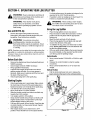
SECTION1: IMPORTANTSAFEOPERATIONPRACTICES
WARNING: This symbol points out important safety instructionswhich, ifnot followed, could endanger
the personal safety and/or property ofyourself and others. Read and follow all instructionsin this manual
before attempting tooperate this machine. Failure to comply with these instructionsmay result in personal
injury. When you see this symbol - heed its warning.
WARNING: Engine exhaust, some of its constituents, and certain vehicle components
contain or emit chemicals known to the State of California to cause cancer, birth defects
or other reproductive harm.
DANGER: This machine was built to be operated according to the rules for safe operation inthis manual.
As with any type of power equipment, carelessness or error on the part of the operator can result in serious
injury. This machine is capable of amputating hands and feet and throwing objects. Failure to observe the
following safety instructions could result in serious injury or death.
GeneralPractices
1. Read, understand, and follow all instructionson the
machine and in the manual(s) before attempting to
assemble and operate. Keep this manual in a safe place
for future and regular reference and for ordering
replacement parts.
2. Be familiar with all controls and proper operation. Know
how to stop the machine and disengage them quickly.
3. Never allow children under 16 years to operate this
machine. Children, 16 years and over, should read and
understand instructionsand safety rules in this manual
and should be trained and supervised by a parent.
4. Never allow adults to operate this machine without
proper instruction.
5. Many accidents occur when more than one person
operates the machine. If a helper isassisting in loading
logs, never activate the control until the helper isa
minimum of 10 feet from the machine.
6. Keep bystanders, helpers, pets, and children at least 20
feet from the machine while it is in operation.
7. Never allow anyone to ride on this machine.
8. Never transport cargo on this machine.
9. Hydraulic log splitters develop high fluid pressures during
operation. Fluid escaping through a pin hole opening can
penetrate your skin and cause blood poisoning,
gangrene, or death. Give attention to the following
instructionsat all times:
a. Do not check for leaks with your hand.
b. Do not operate machine with frayed, kinked,
cracked, or damaged hoses, fitting, or tubing.
c. Stop the engine and relieve hydraulic system
pressure before changing or adjusting fittings,
hoses, tubing, or other system components.
d. Do not adjust the pressure settings of the pump or
valve.
5. Leaks can be detected by passing cardboard or wood,
while wearing protective gloves and safety glasses, over
the suspected area. Look for discoloration of cardboard
or wood.
6. Ifinjured by escaping fluid, see a doctor immediately.
Serious infection or reaction can develop if proper
medical treatment is not administered immediately.
7. Keep the operator zone and adjacent area clear for safe,
secure footing.
8. If your machine isequipped with an internal combustion
engine and it is intended for use near any unimproved
forest, brush, or grass covered land, the engine exhaust
should be equipped with a spark arrester. Make sure you
comply with applicable local, state, and federal codes.
Take appropriate fire fighting equipment with you.
9. This machine should be used for splitting wood only, do
not use it for any other purpose.
10. Follow the instructions in the manual(s) provided with any
attachment(s) for this machine.
Preparation
1. Always wear safety shoes or heavy boots.
2. Always wear safety glasses or safety goggles during
operating this machine.
3. Never wear jewelry or loose clothing that might become
entangled in moving or rotating parts of the machine.
4. Make sure machine ison level surface before operating.
5. Always block machine to prevent unintended movement,
and lock in either horizontal or vertical position.
6. Always operate this machine from the operator zone(s)
specified in the manual.
7. Logs should be cut with square ends prior to splitting.
8. Use log splitter in daylight or under good artificial light.
9. To avoid personal injury or property damage use extreme
care in handling gasoline. Gasoline is extremely
flammable and the vapors are explosive. Serious
personal injury can occur when gasoline is spilled on
yourself or your clothes which can ignite. Wash your skin
and change immediately.
a. Use only an approved gasoline container.
b. Extinguish all cigarettes, cigars, pipes, and other
sources of ignition.
c. Never fuel machine indoors.
d. Never remove gas cap or add fuel while the
engine is hot or running.
e. Allow engine to cool at least two minutes before
refueling.
f. Never overfill the fuel tank. Fill tank to no more
than 1/2 inch below bottom of filler neck to provide
space for fuel expansion.
g. Replace gasoline cap and tighten securely.

h. Ifgasolineisspilled,wipeitofftheengineand
equipment,movemachinetoanotherarea.Wait5
minutesbeforestartingtheengine.
i. Neverstorethemachineorfuelcontainerinside
wherethereisanopenflame,sparkorpilotlight
asonawaterheater,spaceheater,furnace,
clothesdryerorothergasappliances.
j. Allowmachinetocool5minutesbeforestoring.
Operation
1. Before starting this machine, review the "Safety
Instructions". Failure to follow these rules may result in
serious injury to the operator or bystanders.
2. Never leave this machine unattended with the engine
running.
3. Do not operate machine while under the influence of
alcohol, drugs, or medication.
4. Never allow anyone to operate this machine without
proper instruction.
5. Always operate this machine with all safety equipment in
place and working. Make sure all controls are properly
adjusted for safe operation.
6. Do not change the engine governor settings or
overspeed the engine. The governor controls the
maximum safe operating speed of the engine.
7. When loading a log, always place your hands on the
sides of the log, not on the ends, and never use your foot
to help stabilize a log. Failure to do so, may result in
crushed or amputated fingers, toes, hand, or foot.
8. Use only your hand to operate the controls.
9. Never attempt to split more than one log at a time unless
the ram has fully extended and a second log is needed to
complete the separation of the first log.
10. For logs which are not cut square, the least square end
and the longest portion of the log should be placed
toward the beam and wedge, and the square end placed
toward the end plate.
11. When splitting in the vertical position, stabilize the log
before moving the control. Split as follows:
a. Place log on the end plate and turn until it leans
against the beam and is stable.
b. When splitting extra large or uneven logs, the log
must be stabilized with wooden shims or split
wood between the log and end plate or ground.
12. Always keep fingers away from any cracks that open in
the log while splitting. They can quickly close and pinch
or amputate your fingers.
13. Keep your work area clean. Immediately remove split
wood around the machine so you do not stumble over it.
14. Never move this machine while the engine is running.
15. This machine should not be towed on any street, highway
or public road without checking the existing federal, state,
or local vehicle requirements. Any licensing or
modifications such as taillights, etc., needed to comply, is
the sole responsibility of the purchaser. If a "Statement of
Origin" is required in your state, see your local dealer.
16. Do not tow machine faster than 45mph.
17. See Transporting the Log Splitter section in this manual
for proper towing instructions once all federal, local, or
state requirements are met.
MaintenanceandStorage
1. Stop the engine, disconnect the spark plug and ground it
against the engine before cleaning, or inspecting the
machine.
2. Stop the engine and relieve hydraulic system pressure
before repairing or adjusting fittings, hoses, tubing, or
other system components.
3. To prevent fires, clean debris and chaff from the engine
and muffler areas. Ifthe engine is equipped with a spark
arrester muffler, clean and inspect it regularly according
to manufacturers instructions. Replace if damaged.
4. Periodically check that all nuts and bolts, hose clamps,
and hydraulic fittings are tight to be sure equipment is in
safe working condition.
5. Check all safety guards and shields to be sure they are in
the proper position. Never operate with safety guards,
shields, or other protective features removed.
6. The pressure relief valve is preset at the factory. Do not
adjust the valve.
7. Never attempt to move this machine over hilly or uneven
terrain without a tow vehicle or adequate help.
8. For your safety, replace all damaged or worn parts
immediately with original equipment manufacturer's
(O.E.M.) parts only. "Use of parts which do not meet the
original equipment specifications may lead to improper
performance and compromise safety!"
9. Do not alter this machine in any manner, alterations such
as attaching a rope or extension to the control lever, or
adding to the width or height of the wedge may result in
personal injury.

YourResponsibility
Restrict the use of this power machine to persons who read,
understand and follow the warnings and instructions in this
manual and on the machine. Some of the safety labels are re-
produced here. Always follow directions on safety labels
found on your equipment.
• "OCK oeam in norlzontal position. • . " ,
u_ |lUt _ttUl|l_t tU I|IUVU I_ _IILLUr _ - - •
_,,zp _.,FI UUW|| _ _|Ui_ Uy ||a||u
$30230 • Raise jack stand and latch securely public road.
llllllWll

SECTION2: ASSEMBLINGYOURLOGSPLITTER
UnpackingfromCrate
• Pry top, sides, and ends off the crate. Set panels
aside to avoid tire puncture or personal injury.
• Remove and discard plastic bag that covers unit.
• Remove any loose parts if included with unit (i.e.,
operator's manual, etc.)
• Cut and remove straps which secure parts to
bottom of crate. Unbolt any remaining parts which
may be bolted to the bottom of the crate.
WARNING: Use extreme caution while
_b unpacking this machine. Some
components
are very heavy and will require extra people or
mechanical handling equipment to move.
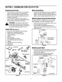
LooseParts(SeeFigure1)
1. Reservoir Tank and Engine-Pump Assembly
2. Engine-Pump Assembly Hardware
3. Wedge, Beam and Cylinder Assembly
4. Tongue Assembly
5. Wheels
6. Hitch Assembly
7. Beam Support/Latch Bracket
8. Log Cradle Brackets and Hardware
9. Fenders
10. Adjustable Jack Stand Assembly
11. Tail Light Kit
12. Hub Cap (2)
Kit -q Beam Support/
Latch Bracket
Hitch Assembly
Wheel & Fender
Assembly
Assembly
Jack Stand
Figure 1
BeforeAssembling
• Disconnect spark plug wire and ground against the
engine to prevent unintended starting of the log
splitter. To locate the spark plug, please refer to the
engine manual, shipped separately with the unit.
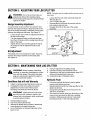
AttachingBeamSupport/LatchBracket
The beam support is already attached to the tongue
before shipping. If not, follow instructions below:
• Remove two hex bolts, lock washers, and hex nuts
from the tongue. See Figure 2.
• Place the beam support/latch bracket on the
tongue and secure with the hardware just removed.
Tighten securely.
kh_ Beam Support/
Latch Bracket
v°C
as er_
Hex Nut
Figure 2
AttachingJackStand
• Remove four hex bolts, lock washers, and hex nuts
that secure jack stand mounting brackets to the
jack stand. See Figure 3.
• Place the jack stand halfway between beam
support/latch bracket and end of tongue.
Hex Bolts_
Mounting_ ___
Brackets
Lock Washer
Figure 3

• Insert hex bolts through top holes in jack stand
mounting brackets and holes in jack stand. Secure
with lock washers and hex nuts. See Figure 3.
• Insert hex bolts through upper holes in the bottom
of mounting brackets and jack stand. Secure with
lock washers and hex nuts. See Figure 3.
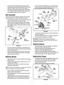
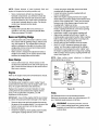
HitchAssembly
The hitch assembly is already attached to the tongue
before shipping. If not, follow instructions below:
• Remove the hardware from the hitch assembly and
place the hitch on the end of the tongue.
• Insert hex bolt through flat washer, end of safety
chain, spacer, and then rear hitch hole. Pivot the
end of safety chain so it faces the ball end of hitch.
See Figure 4.
Figure 4
Bolt
Nut
\
Hitch
Assembly
• Insert other spacer, flat washer, and safety chain
on the other end of the hex bolt and secure with hex
lock nut. See Figure 4.
• Insert hex bolt through the front hole of hitch and
secure with flat washer and hex lock nut. Tighten
both hex nuts to 23 ft-lbs.
• Insert cotter pins through slots in nuts and holes in
axle and secure by bending the ends of the cotter
pins in opposite directions. See Figure 5.
Lock Hex
Washer Nut
Fender _
Hex
Bolt
""-S
Flat
Washer < /
\ ,
Hub Ca
x
Flat
Washer
Reservoir
Tank
Hex Slotted
Nut
Figure 5
• The wheels should spin freely and there should be
no side to side play.
• Place hub caps in position on wheels and tap on to
the axle with a soft hammer or mallet.
IMPORTANT:Maximum tire pressure under any
circumstance is 30 psi. Equal tire pressure should be
maintained at all times.
AttachingFenders
• Remove the hex nuts, lock washers, flat washers,
and hex bolts from the side of tank.
• Determine the proper assembly holes in the
fenders over the tires against the tank.
• Insert hex bolts through flat washers, holes in
fenders, and tank. See Figure 5. Secure fender with
lock washers and hex nuts. Tighten securely.
AttachingWheels
• Block up the reservoir tank assembly about eight to
twelve inches.
• Remove and discard plastic shipping caps on the
outside of the wheels.
• Remove the cotter pin, hex slotted nut, and flat
washer from each axle.
NOTE: Itis recommended that you polish the axles with
emery cloth before you install the wheels.
• Place a wheel on each axle with the valve stem
facing outward. See Figure 5.
• Place a flat washer on each axle and secure with
hex slotted nut.
• Tighten slotted nut until snug and then back off
approximately 1/3 turn or until one of the slots on
the slotted nut lines up with the hole in the axle.
AttachingtheTongue
• Remove two hex bolts, lock washers, and hex nuts
on the front of the reservoir tank. See Figure 6.
• Place the tongue in position and secure with
hardware just removed.
• Remove the reservoir tank from the blocks.
Reservoir
Tank
Hex
Bolts
Figure 6

AttachingBeam
• For shipping purposes, the pressure hose is
attached to the pump on the engine and to the
control valve on the cylinder.
• Disconnect the pressure hose from the adapter on
the pump.
• Stand the wedge, beam, and cylinder assembly
upright with cylinder toward the top. An assistant
may be helpful.
• Remove cotter pin and clevis pin from welded
brackets on beam assembly and move the
reservoir tank assembly in position against the
beam.
• Insert clevis pin just removed through brackets on
beam and reservoir tank assembly. Secure with
cotter pin by bending the ends of the pin in opposite
directions. See Figure 7.
Clevis
Pin_
Cotter
_S Pin
Brackets
Reservoir
Tank
Figure 7
AttachingEngine-PumpAssembly
• Place the engine and pump assembly in position on
the engine mounting bracket with the pump facing
out. See Figure 8.
• Align holes in base of engine with appropriate holes
in engine mounting bracket.
• Secure the engine and pump assembly with four
hex bolts, lock washers, and hex nuts packed with
the Operator's Manual.
• Secure with lock washers and hex nuts. Tighten to
14 ft-lbs.
Engine Hex
Mounting
Bracket
Reservoir
Tank
Washer
Hex
Bolts
Pump
Facing
Out
Figure 8
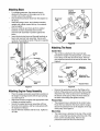
AttachingTheHoses
SuctionHose
• The suction is attached to the reservoir tank,
beneath the engine mounting bracket. Loosen the
hose clamp on the free end of the hose. Remove
any protective insert from the end of the hose. See
Figure 9.
Pressure Attached
Engine
Attached To
Pum Reservoir Tank
Hose
Clam
Suction Hose
Figure 9
• Remove the protective cap from the fitting on the
bottom of the pump (some oil may flow from pump).
Attach the end of the suction hose to the fitting on
the bottom of the pump. Place the hose clamp at
the base of the fitting and tighten securely.
PressureHose
• The pressure hose is attached to the control valve.
Route the hose between the beam and the tongue.
Secure the pressure hose to the adapter on the top
of the pump. See Figure 9.
ReturnHose
• The return hose isattached to the top of the control
valve. Loosen the hose clamp on the free end of the
hose. Cut the securing strap. Remove any
protective insert from the end of the hose.

Removetheprotectivecapfromthefittingontopof
thefilterhead.Attachtheendofthehosetothe
fittingontopofthefilter.Placethehoseclampat
thebaseofthefittingandtightensecurely.See
Figure10.
Attached
ControlValve 'linder
Hose
Clamp
Filte .. /
Head
AttachJd To
Reservoir Tank
Figure 10
Hose
AttachingtheLogCradle
• Pull the beam lock on the beam support/latch
bracket out and pivot it down. Carefully lower the
wedge, beam, and cylinder assembly to the
horizontal position. Pull out and rotate beam lock to
secure beam inthe horizontal position.
NOTE: The hardware for attaching the log cradle is
shipped in the same box with the log cradle.
Place one cradle support bracket against the lower
outside surface of one of the beam flanges.
See Figure 11.
Log Carriage
Cradles Bolts
Cradle
Support
Bracket_
& Hex Nuts
Beam
Flanges
Figure 11
• Insert two carriage bolts through the cradle support
bracket and the beam flange. Secure with lock
washers and hex nuts. Do not tighten at this time.
• Attach the second cradle support bracket to the
same side of the beam in the same manner.
• Place one log cradle over the support brackets and
align the bolt holes.
• Insert four carriage bolts through the log cradle and
cradle support brackets. Secure with lock washers
and hex nuts. Tighten all carriage bolts and nuts.
• Repeat on the other side.
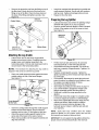
PreparingtheLogSplitter
• Lubricate the beam area where the splitting wedge
will slide with engine oil. Do not use grease.
• Remove vented reservoir dipstick, which is located
in front of the engine on top of the reservoir tank.
See Figure 12.
Reservoir
Di
Figure 12
• Fill the reservoir tank with Dexron III automatic
transmission fluid or 10W AW hydraulic fluid.
• Check fluid level using the dipstick. The reservoir
tank has a capacity of approximately 7 gallons. Do
not overfill.
• Replace vented dipstick securely. Tighten the
dipstick until the top of the threads are flush with the
top of the pipe.
• If not already, disconnect the spark plug wire and
prime the pump, by pulling the recoil starter to turn
the engine over approximately 10 times.
• Reconnect the spark plug wire.
• Start engine according to instructions on page 11.
• Use control handle to engage the wedge to the
farthest extended position and then retract it.
• Refill tank to within the range specified on the
dipstick.
• Extend and retract the wedge 12 complete cycles
to remove trapped air (system is "self-bleeding").
• Much of the original fluid has been drawn into the
cylinder and hoses. Make certain to refill the
reservoir to prevent extreme damage to the
hydraulic pump. Failure to refill the tank will void
your warranty.
NOTE: Some fluid may overflow from the vented
reservoir dipstick as the system builds heat and the
fluid expands and seeks a balanced level.
IMPORTANT:Do not operate the log splitter without the
proper amount of transmission fluid in the reservoir.

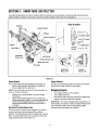
SECTION3: KNOWYOURLOGSPLITTER
Compare the illustrationin Figure 13 below with the controls on your log splitter, and get familiar with itsfeatures
before starting to operate. Know how to stop the machine quickly in the event of an emergency.
Cylinder
ongue
Jack Stand
Horizontal
Beam Lock
Tail Li
Control Handle
Wedge
Beam Assembly
Iht
How it works
Reversei" $
_(_4_ To retuln wedlge
._..J_l / Neutra,l TOstop
Control
Handle F°rwardL_"
Horizontal
Beam Lock
° ,
Vertical
Beam Lock
ControlHandle
The control handle has three positions. See Figure 13.
• Move control handle FORWARD or DOWN to
move wedge down to split wood.
NOTE: Control handle will return to neutral position as
soon as handle is released.
• Release the control handle to stop the wedge
movement.
• Move control handle BACK or UP to return the
wedge toward the cylinder. The control handle will
lock in the disengaged position. It will return to
neutral automatically when the return stroke is
complete.
Horizontal& VerticalBeamLocks
These two locks, as their name suggests, are used to
secure the beam in the horizontal or the vertical
position. The vertical beam lock is located next to the oil
filter. The horizontal beam lock is located on the beam
support latch bracket. See Figure 13.
Figure 13
EngineControls
See the accompanying engine manual for the location
and function ofthe controlson the engine.
StoppingEngine
• Turn engine switch to OFF position.
• Turn off the fuel valve.
• Disconnect spark plug wire and ground against the
engine to prevent unintended starting.
IMPORTANT: This unit isshipped without gasoline or oil
inthe engine. Be certain toservice engine with gasoline
and oilas instructed in the accompanying engine
manual before operating yourmachine.
10

SECTION4: OPERATINGYOURLOGSPLITTER
WARNING: Read, understand, and follow all
instructions and warnings on the machine and
in this manual before operating.
WARNING: Wear leather work gloves,
safety shoes, ear protection, and safety
glasses when operating log splitter. Ensure
safe footing.
GasandOilFill-Up
• Service the engine with gasoline and oil as
instructed in the engine manual packed with your
log splitter. Read instructions carefully.
WARNING: Use extreme care when
handling gasoline. Gasoline is extremely
flammable and the vapors are explosive. Never
fuel machine indoors or while the engine is hot
or running.
NOTE: Gasoline can be added to the engine when the
log splitter is in either the horizontal or vertical position.
However, there are less obstructions when the unit is in
the vertical position.
BeforeEachUse
• Remove the dipstick and check hydraulic fluid level.
Refill if necessary.
• Check engine oil level. Refill if necessary.
• Fill up gasoline if necessary.
• Lubricate with engine oil the beam area where
splitting wedge will slide. Do not use grease to
lubricate. Make sure to lubricate both the front and
the back of the beam face.
• Attach spark plug wire to the spark plug.
StartingEngine
• Attach spark plug wire to spark plug. Make certain
the metal cap on the end of the spark plug wire is
fastened securely over metal tip of the spark plug.
• Turn the fuel valve to the ON position.
• Move choke lever to CHOKE position.
• Slide the throttle control lever about one-third way
towards the FAST position.
• Turn engine switch to ON position.
• Grasp starter handle and pull rope out slowly until
engine reaches start of compression cycle (rope
will pull slightly harder at this point).
• Pull rope with a rapid, full arm stroke. Keep firm grip
on starter handle. Let rope rewind slowly. Repeat
until engine cranks.
• After engine starts, move choke lever to OFF
position. Place throttle lever to the speed desired.
For best performance, the engine is designed to be
operated at the FAST throttle position.
If weather is cold, run wedge up or down beam 6 to
8 times to circulate the hydraulic fluid.
_ WARNING: When starting a warm engine,
_lb he muffler and surrounding areas are hot and
can cause a burn. Do not touch.
UsingtheLogSplitter
• Place the log splitter on level, dry ground.
• Place the beam in either the horizontal or vertical
position and lock in place with the appropriate
locking rod.
• Block the front and back of both wheels.
• Place the log against the end plate and only split
wood in the direction of the grain.
• To stabilize the log, place your hand only on sides
of log. Never place hand on the end between the
log and the splitting wedge.
• Only one adult should stabilize the log and operate
the control handle, so the operator has full control
over the log and the splitting wedge.
ControlHandle
1. Move control handle FORWARD or DOWN to split
wood.
2. Release the control handle to stop the wedge
movement.
3. Move control handle BACK or UP to return the
wedge.
VerticalPosition
• Pull the horizontal beam lock out to release the
beam and pivot the beam to the vertical position.
A
Figure 14
11

• To lock the beam in the vertical position, pull out on
the vertical beam lock and rotate it to secure the
beam. See Figure 13.
• Stand in front of the unit to operate the control
handle and to stabilize the log. See Figure 14A.
HorizontalPosition
• Pull the vertical beam lock out and rotate it down.
See Figure 13. Pivot beam to the horizontal
position. The beam will lock automatically in
horizontal position.
• Stand behind the reservoir tank to operate control
handle and to stabilize the log. See Figure 14B.
OperatingTips
Always:
1. Use clean fluid and check fluid level regularly.
2. Use Dexron III Automatic Transmission Fluid or
10W AW hydraulic fluid.
3. Use a filter (clean or replace regularly)
4. Use a breather cap on fluid reservoir.
5. Make sure pump is mounted and aligned properly.
6. Use a flexible "spider" type coupling between
engine and pump drive shafts.
7. Keep hoses clear and unblocked.
8. Bleed air out of hoses before operating.
9. Flush and clean hydraulic system before restarting
after servicing.
10. Use "pipe dope" on all hydraulic fittings.
11. Allow time for warm-up before splitting wood.
12. Prime the pump before initial start-up by turning
over the engine with spark plug disconnected.
13. Split wood along the grain (lengthwise) only.
Never:
1. Use when fluid is below 20° F or above 150° F.
2. Use a solid engine/pump coupling.
3. Operate through relief valve for long.
4. Attempt to adjust unloading or relief valve settings
without pressure gauges.
5. Operate with air in hydraulic system.
6. Use teflon tape on hydraulic fittings.
7. Attempt to cut wood across the grain.
RaisingandLoweringBeam
• Use control handle to run wedge up and down
beam 6 to 8times to circulate the hydraulic fluid,
which will warm and thin the fluid.
• Place log splitter on a firm, level surface.
• To raise the beam for vertical operation: Pull out
the horizontal beam lock on the tongue.
• Pivot beam lock down to release the beam.
• Move the beam to the vertical position. Secure it
with the beam lock on the reservoir tank assembly.
_ WARNING: Always use the log splitter in the
_ vertical position when splitting heavy logs.
• To lower the beam: Pull out the vertical beam lock
on the reservoir tank.
• Pivot beam lock down to release the beam.
Carefully pull back on beam and lower it to the
horizontal position. See Figure 13.
• Pull out the beam lock on the tongue, pivot it
upwards and release it to hold the beam. Make
certain it is latched securely.
TransportingtheLogSplitter
IMPORTANT:Always turn the fuel valve to OFF position
before transporting the log splitter.
• Lower the beam to its horizontal position. Make
certain the beam is locked securely with the
horizontal beam lock.
• Raise the adjustable jack stand by turning the crank
handle clockwise.
• Attach hitch coupler to aclass I or higher hitch with
a 1-7/8" ball on the towing vehicle, making sure to
latch securely.
a. If the coupler hitch does not fit on the ball,
turn the adjustment nut one turn counter-
clockwise.
b. If the coupler hitch is too loose on the ball,
turn the adjustment nut one turn clockwise.
• Connect the safety chains to the towing vehicle.
WARNING: Do not tow faster than 45mph
and check local, state, and federal
requirements before towing on any publicroad.
NOTE: Use caution when backing up. It is
recommended to use a spotter outside the vehicle.
• Plug in the tail lights as instructed in the tail light kit
manual included with your log splitter.
12

SECTION5: ADJUSTINGYOURLOGSPLITTER
_lb WARNING: Do not at time make
any any
adjustments without first stopping engine,
disconnecting spark plug wire, and grounding it
against the engine.
WedgeAssemblyAdjustment
As normal wear occurs and there is excessive "play"
between the wedge and beam, adjust the bolts on the
side of the wedge assembly to eliminate excess space
between the wedge and the beam. See Figure 15.
• Loosen the jam nuts on the two adjustment bolts on
the side of the wedge.
• Turn the adjustment bolts in until snug and then
back them off slowly until the wedge assembly will
slide on the beam.
• Tighten the jam nuts securely against the side of
the wedge to hold the adjustment bolts in this
position.
GibAdjustment
Periodically remove and replace the "gibs" (spacers)
between the wedge assembly and the back plate.
See Figure 15.
NOTE: The gibs may be rotated and/or turned over for
even wear.
• Loosen the lock nuts under each back plate and
slide the gibs out.
• Turn or replace the gibs.
• Reassemble the back plate and secure with the
lock washers and lock nuts.
• Readjust the bolts on the side of the wedge
assembly.
Jam Nut
\
Adj_
Bolt
Lock
Lock Nut Washer
Figure 15
SECTION6: MAINTAININGYOURLOGSPLITTER
WARNING: Before cleaning, lubricating,
repairing, or inspecting, disengage the control
lever and stop engine. Disconnect the spark
plug wire and ground it against the engine to
prevent unintended starting.
ConditionsthatwillvoidWarranty
1. Failure to maintain proper fluid level in reservoir
2. Changing the relief valve setting or pressure
adjustment of control valve without proper
knowledge and instruction from the factory
WARNING: Higher pressure could cause
_the hoses to burst, to and
cylinder rupture,
intense fluid to be released, which could result
in serious personal injury.
3. Disassembling the pump
4. Use of incorrect hydraulic fluid
5. Allowing the flexible pump coupler to deteriorate
without proper and regular inspection
6. Lack of lubrication or improper lubrication of the
beam or unit
7. Improper adjustment of splitting wedge
8. Excessive heating of the hydraulic system
9. Attempting to start unit in temperatures under 20°F
without pre-heating fluid in reservoir
10. Unattended leaks in hydraulic system
HydraulicFluid
• Check the hydraulic fluid level in the log splitter
reservoir tank before each use.
• Maintain fluid level within the range specified on the
dipstick at all times.
• Change the hydraulic fluid in the reservoir every
100 hours of operation.
• Disconnect the suction hose from the bottom of the
reservoir tank and drain the fluid into a suitable
container. Refill using only Dexron III automatic
transmission fluid or 10W AW hydraulic fluid.
13

NOTE: Please dispose of used hydraulic fluid and
engine oil at approved recycling centers only.
• Since contaminants in fluid may damage the
hydraulic components, you will have to drain the
fluid and flush the reservoir tank and hoses with
kerosene whenever any repair work is performed
on the tank, hydraulic pump or valve. For this job,
contact your nearest service dealer.
HydraulicFilter
• Change the hydraulic filter every 50 hours of
operation. Use only a 10 micron hydraulic filter.
Order part number 723-0405.
BeamandSplittingWedge
• Lubricate both sides of the beam (where it comes
into contact with the splitting wedge), before each
use, with engine oil. The wedge plate on the log
splitter is designed so the gibs on the side of the
wedge plate can be removed and rotated and/or
turned over for even wear.
• Make certain to readjust the adjustment bolts so
wedge moves freely, but no excess space exists
between the wedge plate and the beam.
HoseClamps
• Check, before each use, if hose clamps on the
suction hose (attached to the side of the pump) are
tight. Check the hose clamps on the return hose at
least once a season.
Engine
Refer to the engine manual for all maintenance needs.
FlexiblePumpCoupler
The flexible pump coupler is a nylon "spider" insert,
located between the pump and the engine shaft. Over
time, the coupler will harden and deteriorate.
Replace the coupler if you detect vibration or noise
coming from the area between the engine and the
pump. If the coupler fails completely, you will
experience a loss of power.
IMPORTANT: Never hit the engine shaft in any manner,
as a blow will cause permanent damage to the engine.
• Remove three nuts and lock washers that secure
the pump to the coupling shield. Two nuts are at the
bottom corners and one is in the top center.
• Remove the pump.
• Rotate the engine by slowly pulling starter handle
until engine coupling half set screw is visible.
Loosen set screw using allen wrench and slide
coupling half off engine shaft.
• Loosen set screw on pump coupling half and
remove coupling half.
• Slide new engine coupling half onto the engine
shaft until the end of the shaft is flush with the inner
portion of the coupling half. (There must be space
between end of the engine support bracket and
coupling half). Tighten set screw.
• Install pump coupling half and key on pump shaft.
Rotate coupling half until set screw faces opening
in shield. Do not tighten set screw.
• Install nylon "spider" onto engine coupling half.
• Align pump coupling half with nylon "spider" by
rotating engine using starter handle. Slide coupling
half into place while guiding three mounting bolts
through holes in pump support bracket.
• Secure with nuts and washers removed earlier.
• Set.010" to.060" clearance between the nylon
"spider" and the engine coupling half by sliding a
matchbook cover between the nylon "spider" and
the engine coupling half and moving pump coupling
half as needed. Secure pump coupling half with set
screw. See Figure 16.
NOTE: Make certain proper clearance is obtained
before tightening set screw.
Gear Pump
Set
Sc:e:_ _ r_ j _ _ Steel
"S;ider"_.__ _ Coupling
Insert _ Halves
Clearance_
Figure 16
Tires
See sidewall of tire for recommended pressure.
Maximum tire pressure under any circumstances is 30
p.s.i. Maintain equal pressure on all tires.
WARNING: Excessive pressure (over 30
_L, p.s.i.) when seating beads cause tire/rim
may
assembly to burst with force sufficient to cause
serious injury.
14

SECTION7: STORINGYOURLOGSPLITTER
Prepare your log splitter for storage at the end of the
season or if the log splitter will not be used for 30 days
or more.
WARNING: Never store machine with fuel
in the fuel tank insideof building where fumes
may reach an open flame or spark, or where
ignitionsources are present such as hot water
and space heaters, furnaces, clothes dryers,
stoves, electric motors, etc.
• Clean the logsplitter thoroughly.
NOTE: We do not recommend the use of pressure
washers or garden hose to clean your unit. These may
cause damage to electric components, spindles,
pulleys, bearings or the engine. The use of water will
shorten life and reduce serviceability.
• Wipe unit with an oiled rag to prevent rust,
especially on the wedge and the beam.
• Drain fuel tank. Always drain fuel intoapproved
container outdoors, away from open flame. Be sure
that engine is cool before draining the fuel. Do not
smoke while handling fuel.
• Start the engine and let it run until the fuel lines and
carburetor are empty.
• Remove spark plug, pour approximately 1/2 ounce
(approximately one tablespoon) of engine oil into
cylinder and crank slowly to distribute oil.
• Replace spark plug.
• Do not store gasoline from one season to another.
• Replace your gasoline can if it starts to rust. Rust
and/or dirt in the gasoline will cause problems.
• Store unit in a clean, dry area. Do not store next to
corrosive materials, such as fertilizer.
NOTE: If storing in an unventilated or metal storage
shed, be certain to rustproof the equipment by coating
with a light oil or silicone.
SECTION8: TROUBLESHOOTING
Problem Cause Remedy
Engine fails to start
Engine runs erratic
Engine overheats
1. Spark plug wire disconnected.
2. Fuel tank empty or stale fuel.
3. Fuel shut-off valve closed.
4. Throttle control lever not in correct
starting position.
5. Choke not in CHOKE position.
6. Engine not primed properly.
7. Blocked fuel line.
8. Faulty spark plug.
1. Spark plug wire loose.
2. Unit running on CHOKE.
3. Blocked fuel line or stale fuel.
4. Water or dirt in fuel system.
5. Dirty air cleaner.
6. Carburetor out of adjustment.
1. Engine oil level low.
2. Dirty air cleaner.
3. Carburetor not adjusted properly.
NOTE: For repairs beyond those
1. Connect wire to spark plug.
2. Fill tank with clean, fresh gasoline.
3. Turn the valve to ON position.
4. Move throttle lever to FAST position.
5. Move choke to CHOKE position.
6. Prime engine.
7. Clean fuel line.
8. Clean, adjust gap, or replace.
1. Connect and tighten spark plug wire.
2. Move choke lever to OFF position.
3. Clean fuel line; fill tank with clean, fresh
gasoline
4. Drain fuel tank. Refill with fresh fuel.
5. Clean or replace air cleaner.
6. See authorized service dealer.
1. Fill crankcase with proper oil.
2. Clean or replace air cleaner.
3. See authorized service dealer.
listed above, contact your nearest authorized service center.
15

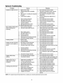
HydraulicTroubleshooting
Problem
Cylinder rod will not move
Slow cylinder shaft speed
while extending and
retracting.
Leaking cylinder
Engine runs but wood will
not split or wood splits too
slowly
Engine stalls during
splitting
Engine will not turn or
stalls under low load
conditions
Leaking pump shaft seal
Cause
1. Broken drive shaft.
2. Shipping plugs left in hydraulic
hoses.
3. Set screws in coupling not adjusted
properly.
4. Loose shaft coupling.
5. Gear sections damaged.
6. Damaged relief valve.
7. Hydraulic lines blocked.
8. Incorrect oil level.
9. Damaged directional valve.
10. Blocked directional valve.
1. Gear sections damaged.
2. Excessive pump inlet vacuum.
3. Slow engine speed.
4. Damaged relief valve.
5. Incorrect oil level.
6. Contaminated oil.
7. Directional valve leaking internally.
8. Internally damaged cylinder.
1. Broken seals.
2. Scored cylinder.
1. Small gear section damaged.
2. Pump check valve leaking.
3. Excessive pump inlet vacuum.
4. Incorrect oil level.
5. Contaminated oil.
6. Directional valve leaking internally.
7. Overloaded cylinder.
8. Internally damaged cylinder.
1. Low horsepower/weak engine.
2. Overloaded cylinder.
1. Engine/pump misalignment.
2. Frozen or seized pump.
3. Low horsepower/weak engine.
4. Hydraulic lines blocked.
5. Blocked directional valve.
1. Broken drive shaft.
2. Engine/pump misalignment.
3. Gear sections damaged.
4. Poorly positioned shaft seal.
5. Plugged oil breather.
Remedy
1. See authorized service dealer.
2. Disconnect hydraulic hoses, remove
shipping plugs, reconnect hoses.
3. See operator's manual for correct
adjustment.
4. Correct engine/pump alignment as
necessary.
5. See authorized service dealer.
6. See authorized service dealer.
7. Flush and clean hydraulic system.
8. Check oil level.
9. See authorized service dealer.
10. Flush and clean hydraulic system.
1. See authorized service dealer.
2. Make certain pump inlet hoses are clear
and unblocked-use short, large
diameter inlet hoses.
3. See authorized service dealer.
4. See authorized service dealer.
5. Check oil level.
6. Drain oil, clean reservoir, and refill.
7. See authorized service dealer.
8. See authorized service dealer.
1. See authorized service dealer.
2. See authorized service dealer.
1. See authorized service dealer.
2. See authorized service dealer.
3. Make certain pump inlet hoses are clear
and unblocked.
4. Check oil level.
5. Drain oil, clean reservoir, and refill.
6. See authorized service dealer.
7. Do not attempt to split wood against the
grain.
8. See authorized service dealer.
1. See authorized service dealer.
2. Do not attempt to split wood against the
grain or see authorized service dealer.
1. Correct alignment as necessary.
2. See authorized service dealer.
3. See authorized service dealer.
4. Flush and clean hydraulic system.
5. Flush and clean hydraulic system.
1. See authorized service dealer.
2. Correct alignment as necessary.
3. See authorized service dealer.
4. See authorized service dealer.
5. Make certain reservoir is properly
vented.
NOTE: For repairs beyond those listed here, contact your nearest authorized service center,
16

NOTES
17

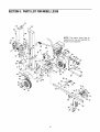
SECTION9: PARTSLISTFORMODELLS338
31
24
27
35
4
20
48
46
27
I
I
I
NOTE: The engine, shown here for
reference only, may not resemble the
engine on your equipment,
59
53
56
72 71
66 70
18

ModelLS338
Ref.
Part No.
No.
1. 781-0686
3. 781-0682
4. 710-3097
5. 719-0550
6. 712-0239
7. 710-1018
8. 710-1806
9. 781-0351
10. 712-0711
11. 710-0459A
12. 781-0790
13. 736-0921
14. 710-0514
15. 781-0525
20, 681-0129A
21. 714-0211
22. 718-0313
23. 711-1135
24. 727-0471
25. 727-0443
26. 781-0526
27. 726-0132
28. 737-0153
29. 737-0192
30. 737-0235
31. 718-0481
32. 737-0316
33. 723-0405
34. 727-0502
35. 781-0538
36. 714-0470
37. 738-0805
38. 726-0214
39. 732-0583
40. 736-0116
41. 781-0690
42. 737-0348A
43. 781-04002
44. 736-0371
45. 710-3038
46. 681-0178A
47. 736-0119
48. 712-3010
49. 710-0409
Part Description
Log Tray Bracket
LogTray
Carriage Bolt 3/8-16 x 1,0
Wedge Assembly
Lock Nut 1/2-20
Hex Cap Screw 1/2-20 x 2,75
Hex Screw 1/2-13 x 3,25
Adjustable Gib
Hex Jam Nut 3/8-24
Hex Cap Screw 3/8-24 x 1,5
Back Plate
Lock Washer 1/2
Hex Screw 3/8-16 x 1,0
Dislodger
Beam Assembly
Cotter Pin
Hydraulic Cylinder 31/33 Ton
Clevis Pin
Hydraulic Tube
Return Hose 3/4" ID x 44" Lg,
Hose Guard
Hose Clamp 5/8"
Return Elbow
90 Degree Solid Male Adapter
3/4" Hose Adapter
Control Valve
Filter Housing
Oil Filter
High Pressure Hydraulic Hose
Hose Guard
Cotter Pin 1/8"
Hinge Pin 1/2 x 4,8" Lg,
Push Cap
Compression Spring 4"
Flat Washer,635 ID x,93 OD
Locking Rod
Vented Dipstick
Fender Assembly
Lock Washer 5/16
Hex Screw
Frame Assembly 7,0 Gal
Lock Washer 5/16
Hex Nut 5/16-18
Hex Cap Screw 5/16-24 x 1,75
Ref.
No.
50.
51.
53.
54.
55.
56.
57.
58.
59.
60.
61.
62.
63.
64.
65.
66.
67.
68.
69.
70.
71.
72.
73.
74.
75.
76.
77.
78.
79.
80.
81.
82.
83.
84.
85.
86.
87.
89.
90.
92.
93.
94.
95.
Part No.
710-1253
781-1100
736-0119
711-0396
719-0315
714-0114
712-0123
718-0685
781-0097
737-0264
718-0684
726-0174
727-0451
710-0521
712-0798
736-0169
781-0680A
710-0411
681-0110
681-0006
710-0944
736-0262
713-0433
750-0497
727-0311
712-0375
712-3008
721-0168
741-0987
634-0186
634-0180
736-0351
712-0359
714-0162
734-0873
681-0074
625-0009
781-0624
712-0123
712-3022
712-0292
710-0157
710-0347
Part Description
Hex Cap Screw 5/16-24 x 5,25
Pump Mounting Plate
Lock Washer 5/16
Spacer.385 x.623 x,750 Lg,
Coupling Shield
Key
Hex Nut 5/16-24
Flex Coupling
Rear Coupling Support Bracket
Adapter 7/8-14
Pump (16 gmp)
Hose Clamp
Suction Hose
Hex Cap Screw 3/8-16 x 3,0
Hex Nut 3/8-16
Lock Washer 3/8
Tube
Hex Cap Screw 3/8-16 x 4,0
Support Beam Assembly
Adjustable Jack Stand
Hex Cap Screw 3/8-16 x 4,25
Flat Washer,385 ID x,870 OD
Chain
Spacer
Hitch Coupler
Lock Nut 3/8-16
Hex Jam Nut 3/8-16
Bearing Seal
Bearing Cone
Wheel Assembly
Rim Assembly
Flat Washer,76" ID x 1,5" OD
Slotted Nut 3/4-16
Cotter Pin 5/32" x 1-1/4" Lg,
Hub Cap
Light Bracket Assembly LH
Tail Light Assembly
Light Bracket Assembly RH
Hex Nut 5/16-24
Lock Nut 1/2-13
Tinn Clip Nut 1/4-20
Hex Screw 5/16-24
Hex Screw 3/8-16 x 1,75
19

MANUFACTURER'S LIMITED WARRANTY FOR:
The limited warranty set forth below is given by Troy-Bilt LLC
with respect to new merchandise purchased and used inthe
United States, its possessions and territories,
Troy-Bilt LLC warrants this product against defects for a
period of two (2) years commencing on the date of original
purchase and will, at its option, repair or replace, free of
charge, any part found to be defective in materials or
workmanship. This limited warranty shall only apply if this
product has been operated and maintained in accordance
with the Operator's Manual furnished with the product, and
has not been subject to misuse, abuse, commercial use,
neglect, accident, improper maintenance, alteration,
vandalism, theft, fire, water, or damage because of other peril
or natural disaster, Damage resulting from the installation or
use of any accessory or attachment not approved by Troy-Bilt
LLC for use with the product(s) covered by this manual will
void your warranty as to any resulting damage,
Normal wear parts or components thereof are subject to
separate terms as follows: All normal wear parts or
component failures will be covered on the product for a period
of 90 days regardless of cause. After 90 days, but within the
two year period, normal wear part failures will be covered
ONLY IF caused by defects in materials or workmanship of
OTHER component parts, Normal wear parts and
components include, but are not limited to: batteries, belts,
blades, blade adapters, grass bags, rider deck wheels, seats,
snow thrower skid shoes, shave plates, auger spiral rubber,
and tires,
HOW TO OBTAIN SERVICE: Warranty service is available,
WITH PROOF OF PURCHASE, through your local authorized
service dealer, To locate the dealer in your area, check your
Yellow Pages, or contact Troy-Bilt LLC at P,O, Box 361131,
Cleveland, Ohio 44136-0019, or call 1-866-840-6483 or 1-
330-558-7220, or log on to our Web site at www,troybilt,com,
This limited warranty does not provide coverage in the
following cases:
a,
b,
C,
The engine or component parts thereof, These items
carry a separate manufacturer's warranty, Refer to
applicable manufacturer's warranty for terms and
conditions.
Log splitter pumps, valves, and cylinders have a sepa
rate one year warranty.
Routine maintenance items such as lubricants, filters,
blade sharpening, tune-ups, brake adjustments, clutch
adjustments, deck adjustments, and normal
deterioration of the exterior finish due to use or
exposure,
d, Troy-Bilt LLC does not extend any warranty for
products sold or exported outside of the United States,
its possessions and territories, except those sold
through Troy-Bilt LLC's authorized channels of export
distribution,
e, Parts that are not genuine Troy-Bilt parts are not
covered by this warranty,
f, Service completed by someone other than an
authorized service dealer is not covered by this
warranty,
g, Transportation charges and service calls are not
covered,
No implied warranty, including any implied warranty of
merchantability of fitness for a particular purpose,
applies after the applicable period of express written
warranty above as to the parts as identified. No other
express warranty, whether written or oral, except as
mentioned above, given by any person or entity,
including a dealer or retailer, with respect to any product,
shall bind Troy-Bilt LLC. During the period of the
warranty, the exclusive remedy is repair or replacement
of the product as set forth above.
The provisions as set forth in this warranty provide the
sole and exclusive remedy arising from the sale. Troy-Bilt
LLC shall not be liable for incidental or consequential
loss or damage including, without limitation, expenses
incurred for substitute or replacement lawn care services
or for rental expenses to temporarily replace a warranted
product.
Some states do notallow the exclusion or limitation of
incidental or consequential damages, or limitations on how
long an implied warranty lasts, so the above exclusions or
limitations may not apply to you.
In no event shall recovery of any kind be greater than the
amount of the purchase price ofthe product sold. Alteration
of safety features of the product shall void this warranty.
You assume the risk and liability for loss, damage, or injury to
you and your property andtor to others and their property
arising out of the misuse or inability to use the product,
This limited warranty shall not extend to anyone other than the
original purchaser or to the person for whom it was purchased
as a gift,
HOW STATE LAW RELATES TO THIS WARRANTY: This
limited warranty gives you specific legal rights, and you may
also have other rights which vary from state tostate.
Troy-BiltLLC,P.O.BOX361131CLEVELAND,OHIO44136-0019;Phone:1-866-840-6483,1-330-558-7220
-
 1
1
-
 2
2
-
 3
3
-
 4
4
-
 5
5
-
 6
6
-
 7
7
-
 8
8
-
 9
9
-
 10
10
-
 11
11
-
 12
12
-
 13
13
-
 14
14
-
 15
15
-
 16
16
-
 17
17
-
 18
18
-
 19
19
-
 20
20


Troy-Bilt Log Splitter LS338 User manual
- Category
- Log splitters
- Type
- User manual
- This manual is also suitable for
Ask a question and I''ll find the answer in the document
Finding information in a document is now easier with AI
Related papers
-
Troy-Bilt 550 Series User manual
-
Troy-Bilt 550 Series Owner's manual
-
Troy-Bilt LS275 User manual
-
-
-
-
Troy-Bilt 24BF572B711 User manual
-
-
-