Page is loading ...

CLTI-2DIMU8/CLXI-2DIMU8
Terminal Block and Module
Installation Guide
Description
The Crestron
®
230 V, 2-Feed, 8-Dimmer Terminal Block and Module (CLTI-2DIMU8 and
CLXI-2DIMU8) are considered single entities and must be used together. They ship
separately to permit termination of the eld wiring to the terminal block (CLTI) prior to
installation of the module (CLXI). The terminal block is designed to terminate the circuit
feed (LINE and NEUTRAL) and distribute the controlled circuit (LOAD) to the xtures. The
module connects to the terminal block and performs dimming control of LED,
incandescent, magnetic low-voltage, or dimmable 2-wire uorescent lighting loads.
The maximum load is 2.5 A per channel; the maximum load is 20 A total for the
CLXI-2DIMU8. The CLXI-2DIMU8 accepts two 10 A feeds that can be different phases.
An oversize heat sink dissipates heat efciently. There are LEDs on the module to indicate
communication to a Cresnet
®
network, input power to the module, and output power to
the load.
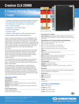
The CLTI terminals and CLXI modules are shown in the following illustrations.
CLTI-2DIMU8 Terminal Block with Left- and Right-Side CLXI-2DIMU8 Labels
Additional Resources
Visit the product page on the Crestron website
(www.crestron.com) for additional information
and the latest rmware updates. Use a QR
reader application on your mobile device to
scan the QR image.
CLX-2DIMU8
DIM 1
DIM 2
DIM 3
DIM 4
DIM 5
DIM 6
DIM 7
DIM 8
N IN 1
N OUT 1
N OUT 2
N OUT 3
N OUT 4
N IN 2
N OUT 5
N OUT 6
N OUT 7
N OUT 8
LINE 1
LINE 2
2 FEED
8 DIM
120VAC 60 Hz
SINGLE PHASE
16A MAX/FEED
CLX-2DIMU8
DIM 8
DIM 7
DIM 6
DIM 5
2 FEED
8 DIM
120VAC 60 Hz
SINGLE PHASE
16A MAX/FEED
N OUT 8
N OUT 7
N OUT 6
N OUT 5
N IN 2
DIM 5
LINE 2
DIM 4
DIM 3
DIM 2
DIM 1
LINE 1
N OUT 4
N OUT 3
N OUT 2
N OUT 1
N IN 1
CLXI-2DIMU8 Module (Connects to a CLTI-2DIMU8)
Terminal Block and Module Layout for a Double-Wide Enclosure (CLTI-2DIMU8 and
CLXI-2DIMU8 Shown)
Ground bus
CLTI- terminal
block
CLXI- module
Ground bus
CLTI- terminal block CLTI- terminal blockCLXI- module
CLX-2DIMU8
DIM 8
DIM 7
DIM 6
DIM 5
2 FEED
8 DIM
120VAC 60 Hz
SINGLE PHASE
16A MAX/FEED
N OUT 8
N OUT 7
N OUT 6
N OUT 5
N IN 2
DIM 5
LINE 2
DIM 4
DIM 3
DIM 2
DIM 1
LINE 1
N OUT 4
N OUT 3
N OUT 2
N OUT 1
N IN 1
NOTE: Unless otherwise indicated, the lighting system specied in this guide is
modular, requiring assembly in the eld by a licensed electrician in accordance with all
national and local codes.
If an assembled UL
®
Listed panel is required, Crestron offers this service through its UL
Listed panel shop. This includes complete in-factory system conguration and assembly
by Crestron for an additional fee.
Terminal Block Installation and Field Wiring
Terminal block installation requires installation of the supplied adhesive label and the
terminal block. The adhesive label provides the labeling for each terminal in the terminal
block and is designed to accommodate installation into the left or right side of a cabinet.
Refer to the illustrations that follow for details.
WARNING: The CLXI-2DIMU8 may be powered from multiple circuit breakers.
NOTE: Both left-side and right-side adhesive wiring labels are provided. The left-side
labels are used in both single- and double-wide enclosures. The right-side labels are
used only in double-wide enclosures.
1. Remove the backing from the left- or right-side adhesive wiring label.
2. Apply the adhesive label by aligning the holes in the label with the holes on the
Crestron Automation Enclosure where the terminal block is to be mounted. The
wiring label lies beneath the terminal block.
3. Use the two supplied self-tapping Phillips pan head screws (8B x 1/4 in length) to
secure the terminal block to the Crestron Automation Enclosure.
CAUTION: Bypass jumpers are provided to allow testing of circuits and to protect
the module during installation. When properly secured by ve screws, each of the
two jumpers on the brown and red sections of the terminal block shorts the line in
to dim out so that the circuit is energized. Do not remove any bypass jumpers until
all feed and load wiring has been completed, the circuit has been tested for
electrical faults, and the module has been installed. Refer to “Module Installation
and Wiring” for details.
Furthermore, the two jumpers on the blue sections of the terminal block tie the
neutral ins to the neutral outs. These jumpers should never be removed.
NOTE: Use copper conductors only—rated 75 °C or greater.
4. Turn off the circuit breakers.
5. Connect the circuit feed (line and neutral) and controlled circuit (load) wires to the
terminal block per the markings provided on the wiring label. Terminal blocks accept
one 2.5–6 mm
2
wire. Strip the wires to 12 mm (1/2 in). Tighten terminal blocks to
1 Nm.
6. Grounding terminal blocks are available in the cabinet for termination of ground
wires. Tighten to 4 Nm (2.5–6 mm
2
), 4.5 Nm (10 mm
2
), or 5.1 Nm (16–25 mm
2
).
7. Test each circuit for electrical faults by turning on each of the circuit breakers and
checking that the breakers do not trip and that power is delivered to the proper
loads.
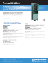
Wiring the Terminal Block to the Feed and Load(s) (Single-Wide and Left-Side Double-Wide
Enclosures)
LINE 1
Connection from a
15 or 20 A circuit
breaker
Bypass
jumpers
Terminal
block
To loads
Left-side
wiring label
LINE 2
Connection from a
15 or 20 A circuit
breaker
Ground
bus
Module
location
label
NEUTRAL
NEUTRAL
GND
CLX-2DIMU8
DIM 1
DIM 2
DIM 3
DIM 4
DIM 5
DIM 6
DIM 7
DIM 8
N IN 1
N OUT 1
N OUT 2
N OUT 3
N OUT 4
N IN 2
N OUT 5
N OUT 6
N OUT 7
N OUT 8
LINE 1
LINE 2
2 FEED
8 DIM
120VAC 60 Hz
SINGLE PHASE
16A MAX/FEED
CLTI-2DIMU8 CLXI-2DIMU8
Specications
Specications are listed in the table below.
Installation
A licensed electrician must mount the terminal block and module into a Crestron
Automation Enclosure in accordance with all national and local codes.
CAUTION: This equipment is for indoor use only and needs to be air cooled. Mount in a
well-ventilated area. The ambient temperature must be 10° to 40 °C (32° to 104 °F). The
relative humidity must be 10% to 90% (noncondensing).
NOTE
: For 2-feed systems, the two input lines can be different phases.
NOTE: When connecting to an arc fault breaker, ensure the load does not exceed
1,000 W total. Crestron certied breakers have a 2,000 W limit.
IMPORTANT NOTES: When controlling magnetic low-voltage transformers:
• Do not use a CLXI-2DIMU8 module for switching or dimming large magnetic
transformers (>100 VA).
• Do not connect more than eight magnetic transformers on any one output, regardless
of lamp wattage.
• Do not hot plug transformers or add or remove bypass jumpers while the output
channel is energized.
• Do not mix magnetic and electronic transformers on the same output channel.
Failure to follow the guidelines above can lead to damage of the dimmer module and
transformers.
NOTE: Before using the CLXI-2DIMU8, ensure the device is using the latest rmware.
Check for the latest rmware for the CLXI-2DIMU8 at www.crestron.com/rmware. Load
the rmware onto the device using Crestron Toolbox™ software.
Install terminal blocks along the left side of single-wide enclosures and along the outside
edges (left and right sides) of double-wide enclosures. Install modules along the right side
of single-wide enclosures and side-by-side in the center of double-wide enclosures. When
installing modules and terminal blocks in a double-wide enclosure, be sure to invert the
units on the right side so that they can be properly wired. Refer to the illustrations that
follow when considering the location of terminal blocks and modules within an enclosure.
NOTE: Modules and terminal blocks must be installed into the lowest available spaces
and continue toward the top of the enclosure.
Terminal Block and Module Layout for a Single-Wide Enclosure (CLTI-2DIMU8 and
CLXI-2DIMU8 Shown)
* When connecting to a third-party arc fault breaker, ensure that the total load does not exceed 1,000 W
per feed.
SPECIFICATION DETAILS
Load Ratings
Dimmer Channels 8
Per Channel 2.5 A
Per Group Channels 1–4: 10 A
Channels 5–8: 10 A
Module Total 20 A*
Minimum Load 0 A
Dimming Modes Auto-load detection, forced reverse-phase, forced
forward-phase
Load Types LED, incandescent, magnetic low-voltage, electronic
low-voltage, 2-wire uorescent and nondimmable
lighting
Power Requirements One or two feeds (the same or different phases)
230 Vac, 50/60 Hz, single-phase
Environmental
Temperature 0° to 40 °C (32° to 104 °F)
Humidity 10% to 90% RH (noncondensing)
Heat Dissipation 12 Btu/h + (3.8 Btu/h x Load Current in A)
88 Btu/h at maximum load
Enclosure Gray metal with black heat sink, surface mount
module with two integral mounting anges;
Occupies 1 module space in a CAEN or CAENIB
enclosure
Voltage Limit for
SELV/PELV Circuits
24 V

TROUBLE POSSIBLE CAUSE(S) CORRECTIVE ACTION
The output does not appear
to dim below 50%.
The dimmer channel may
have been damaged.
Contact Crestron
customer service.
The connected LED load
buzzes and ickers when
dimmed.
An incompatible LED
xture is installed.
Verify the connected LED
load is dimmable and has
been tested. Refer to
Crestron’s Light Fixture
Compatibility Listing at
www.crestron.com/
resources/lighting-xture-
compatibility.
An incorrect dimming
phase is selected.
Set the dimming phase to
Auto or Reverse Phase
mode to reduce current
spikes to load.
The connected LED load
ickers or turns off when
dimmed to a low level.
The minimum dimming
level is set too low.
Adjust the minimum
dimming level to match
the minimum level
required by the LED load.
The LED load does not dim
to a low brightness level.
An incorrect dimming
phase is selected.
Set the dimming phase to
Forward Phase mode.
As of the date of manufacture, these products have been tested and found to comply with
specications for CE marking.
The product warranty can be found at www.crestron.com/warranty.
The specic patents that cover Crestron products are listed at patents.crestron.com.
Certain Crestron products contain open source software. For specic information, please visit
www.crestron.com/opensource.
Crestron, the Crestron logo, Cresnet, and Crestron Toolbox are either trademarks or registered
trademarks of Crestron Electronics, Inc. in the United States and/or other countries. UL is either a
trademarks or registered trademarks of Underwriters Laboratories, Inc. in the United States and/or
other countries. Other trademarks, registered trademarks, and trade names may be used in this
document to refer to either the entities claiming the marks and names or their products.
Crestron Electronics, Inc. Installation Guide - DOC. 7851B
15 Volvo Drive Rockleigh, NJ 07647 (2047970)
Tel: 888.CRESTRON 01.17
Fax: 201.767.7576 Specications subject to
www.crestron.com change without notice.
Crestron disclaims any proprietary interest in the marks and names of others. Crestron is not responsible
for errors in typography or photography.
This document was written by the Technical Publications department at Crestron.
©2017 Crestron Electronics, Inc.
Wiring the Terminal Block to the Feed and Load(s) (Right-Side Double-Wide Enclosures)
LINE 1
Connection from a
15 or 20 A circuit
breaker
Bypass
jumpers
Terminal
block
To loads
Right-side
wiring label
LINE 2
Connection from a
15 or 20 A circuit
breaker
Ground
bus
Module
location
label
NEUTRAL
NEUTRAL
GND
CLX-2DIMU8
DIM 8
DIM 7
DIM 6
DIM 5
2 FEED
8 DIM
120VAC 60 Hz
SINGLE PHASE
16A MAX/FEED
N OUT 8
N OUT 7
N OUT 6
N OUT 5
N IN 2
DIM 5
LINE 2
DIM 4
DIM 3
DIM 2
DIM 1
LINE 1
N OUT 4
N OUT 3
N OUT 2
N OUT 1
N IN 1
Module interconnect
cable attached
Connection not
made
Controlling Local Loads and Setting Load Type
Use Local mode to verify that each load is connected to the proper output on the modules.
Refer to the illustration that follows for button locations.
1. Press the SETUP button to enter Local mode. Output 1 turns full on.
2. Press the mode button to cycle through the dimming modes, and press the SETUP
button to save the setting and advance to the next output. The dimming mode is
identied by the blinking LED.
● Green indicates forced reverse phase.
● Red indicates forced forward phase.
● Yellow and green indicate auto-select reverse phase.
● Yellow and red indicate auto-select forward phase.
● Red and green indicate non-dim.
3. Press the SETUP button to advance to output 2. Repeat step 2 for the remaining
outputs.
4. After turning on the last output, press the SETUP button again to turn on all outputs
and verify that they are operating correctly.
5. Press the SETUP button to turn off all outputs and LEDs and exit Local mode.
NOTE: Adjustment to the dimming mode locally is disabled if the dimming phase is
set in the SIMPL program.
CLXI-2DIMU8 Mode and SETUP Button Locations
Setup button
Mode button
Brown from breaker
Brown from breaker
Blue from panel or
breaker
Red to loads
Red to loads
Blue to loads
Blue to loads
CLX-2DIMU8
DIM 1
DIM 2
DIM 3
DIM 4
DIM 5
DIM 6
DIM 7
DIM 8
N IN 1
N OUT 1
N OUT 2
N OUT 3
N OUT 4
N IN 2
N OUT 5
N OUT 6
N OUT 7
N OUT 8
LINE 1
LINE 2
2 FEED
8 DIM
120VAC 60 Hz
SINGLE PHASE
16A MAX/FEED
Blue from panel or
breaker
Brown from breaker
Brown from breaker
Blue from panel or
breaker
Red to loads
Red to loads
Blue to loads
Blue to loads
Blue from panel or
breaker
CLX-2DIMU8
DIM 8
DIM 7
DIM 6
DIM 5
2 FEED
8 DIM
120VAC 60 Hz
SINGLE PHASE
16A MAX/FEED
N OUT 8
N OUT 7
N OUT 6
N OUT 5
N IN 2
DIM 5
LINE 2
DIM 4
DIM 3
DIM 2
DIM 1
LINE 1
N OUT 4
N OUT 3
N OUT 2
N OUT 1
N IN 1
Jumper removed
Jumper installed
Jumper removed
Jumper installed
CLX-2DIMU8
DIM 8
DIM 7
DIM 6
DIM 5
2 FEED
8 DIM
120VAC 60 Hz
SINGLE PHASE
16A MAX/FEED
N OUT 8
N OUT 7
N OUT 6
N OUT 5
N IN 2
DIM 5
LINE 2
DIM 4
DIM 3
DIM 2
DIM 1
LINE 1
N OUT 4
N OUT 3
N OUT 2
N OUT 1
N IN 1
Jumper removed
Jumper installed
Jumper removed
Jumper installed
CLX-2DIMU8
DIM 1
DIM 2
DIM 3
DIM 4
DIM 5
DIM 6
DIM 7
DIM 8
N IN 1
N OUT 1
N OUT 2
N OUT 3
N OUT 4
N IN 2
N OUT 5
N OUT 6
N OUT 7
N OUT 8
LINE 1
LINE 2
2 FEED
8 DIM
120VAC 60 Hz
SINGLE PHASE
16A MAX/FEED
Troubleshooting
The following table provides corrective actions for possible trouble situations. If further
assistance is required, please contact a Crestron customer service representative.
The module displays error codes using the dimmer output LEDs. The LED blinks a pattern,
such as 1-2 or 2-4, to indicate the error on that output. For example, a 1-2 error blinks the
LED 1 time, pauses for 1 second, blinks two times, pauses for two seconds, and then
repeats until the error is corrected. A 2-4 error blinks the LED blinks two times, pauses for
1 second, blinks four times, pauses for two seconds, and then repeats until the error is
corrected. Refer to the following table for possible corrections.
5. Turn on the circuit breakers and verify that the green PWR LED on the module lights,
the breakers do not trip, and the power is delivered to the loads.
6. Turn off the circuit breakers.
NOTE: Before removing the bypass jumpers, make sure to properly connect and
program the control system that provides functionality to the system.
7. Remove the bypass jumpers on the brown and red sections of the terminal block.
The jumpers on the blue sections of the terminal block must remain installed.
Module Installation and Wiring
CAUTION: The module contains electrostatic sensitive devices (ESDs); the unit must be
handled from the metal chassis. Do not touch the PC board or components.
NOTE: Install the modules after the enclosure has been completely wired. Refer to
“Terminal Block Installation and Field Wiring” for details.
Install and wire the module.
1. Turn off the circuit breakers.
2. Use the four supplied self-tapping Phillips pan head screws (8B x 1/4 in length) to
secure the module to the enclosure.
3. Connect the wires from the module to the terminal block. Each wire exits the module
directly in line with, and is the same color as, the terminal to which it should be
connected. Wires are prestripped to 12 mm (1/2 in). Tighten to 1 Nm.
4. If the module is being installed above another module within the enclosure, attach
the supplied module interconnect cable between the two modules. The illustration
that follows shows the area within a double-wide enclosure where the corners of
four modules meet.
NOTE: One wire on the module interconnect cable may be a different color from
the rest. The color has no bearing on its orientation during installation.
Using Module Interconnect Cable to Wire One Module to Another
Wiring the Terminal Block to the Module (Single-Wide and Left-Side Double-Wide Enclosures)
Removing the Line Jumpers after Testing (Single-Wide and Left-Side Double-Wide Enclosures
and Right-Side Mounted CLTI-2DIMU8 Shown)
Wiring the Terminal Block to the Module (Right-Side Double-Wide Enclosures)
8. Turn on the circuit breakers.
NOTE: Power must be supplied to LINE 1 for the module to communicate with the
control system or for any of the circuits to operate.
9. If the program is not yet running, test the loads using Local mode.
ERROR
CODE
ERROR NAME FAULT DESCRIPTION
1-1 Master MCU
Stuck in
Bootloader
The rmware upgrade has failed or has been aborted,
leaving the master processor in bootloader. Reinitiate
rmware upgrade from Crestron Toolbox software.
1-2 Dimming
Processor
Unresponsive
Communications to the corresponding dimming
processor have failed. Conrm that power is supplied
to LINE 2/N IN 2. Then reboot the unit or contact
Crestron customer service.
1-3 Dimming
Processor
Firmware
Upgrade Failed
The rmware upgrade has failed or has been aborted,
leaving the dimming processor in bootloader.
Reinitiate the rmware upgrade from Crestron
Toolbox.
2-1 Overcurrent
Tripped
A short circuit or overload has been detected and
output has been switched off.
• Check wiring for shorts.
• Verify that the total load connected to the
channel is less than 2.5 A.
• Verify that the dimming phase has not been set
to Forward Phase mode if an incandescent or
electronic load is connected.
The channel attempts to resume normal operation
after receiving another command to turn
on.
2-2 Shorted FET The dimmer channel has failed. Disconnect the load
and contact Crestron Technical Support.
2-3 Overtemperature
Tripped
The dimming channel has overheated and shut down
due to excessive load.
• Verify that the total load connected to the
channel is less than 2.5 A.
• Verify that the panel ventilation is not blocked.
The channel resumes normal operation after cooling.
2-4 Overvoltage
Detected
High-voltage spikes have been detected and output
has been shut down.
If a magnetic load is connected, verify that the
dimming phase has been set to Forward Phase
mode.
3-1 Zero Cross Fault The dimmer is unable to lock onto the ac line.
If the unit is powered by a generator, verify that
generator output is 50/60 Hz and stable.
/