Page is loading ...

Miller
June1995
Effective
With
Form:
Serial
No.
OM-167302A
KF903919
OWNERS
MANI
UAL
t~P~
K~7\
~
Maxtron
450TM
CC/C
V
DC
Welding
Power
Source
For
GMAW,
GTAW,
SMAW,
FCAW,
CAC-A,
GMAW-P,
GTAW-P,
And
SAW
Welding
Rated
Welding
Output
Voltage
Range
In
CV
Mode
Amperage
Range
In
CC
Mode
Maximum
Open-Circuit
Voltage
DC
Amperes
Input
at
Rated
Load
Output
50
Hz,
Three-Phase
380V
415V
29
I
(08)*
I
I
400
A
@
34
Volts
DC.
100%
Duty
Cycle
12
38
V
5
565
A
80
VDC
While
idling
27
(0.7)
coveLom
4/95
-
ST-800
763-A
'
1995
MILLER
Electric
Mtg.
Co.
PRINTED
IN
USA

Ktt
MILLERS
TRUE
BLUETM
LIMITED
WARRANTY~
Effective
January
1,1995
(Equipment
with
a
serial
number
preface
of
KD
or
newer)
This
limited
warranly
supersedes
eli
previous
MILLER
warrsnties
end
is
exclusive
with
no
other
gusranlees
or
wsrranties
expressed
or
implied.
I.
LIMITED
WARRANTY
Subject
10
the
terms
end
conditions
below,
MILLER
Electric
Mfg.
Co.,
Applelon,
Wisconsin.
wsrrsnts
lo
its
originsl
retsil
purchsser
thst
new
MILLER
equipment
sold
after
the
effective
date
of
this
limited
wsrrenty
is
free
of
de
feds
in
msterial
and
workmsnship
al
the
time
it
is
shipped
by
MILLER.
THIS
WAR
RANTY
IS
EXPRESSLY
IN
LIEU
OF
ALL
OTHER
WARRANTIES,
EXPRESS
OR
IMPLIED,
INCLUDING
THE
WARRANTiES OF
MERCHANTABILITY
AND
FIT
NESS.
Within the
warranty
periods
listed
below,
MILLER
will
repair
or
replace
any
war
mnted
parts
or
components
that
fail
due
to
such
defecta
in
material
or
workmanship.
MILLER
musi
be
notified
in
writing
within
thirty
(30)
days
of
such
defect
or
failure,
al
which
time
MILLER
will
provide
instructions
on
the
warranty
claim
procedures
to
be
followed.
MILLER
shall
honor
warranty
claims
on
warranted
equipment
listed
below
in
the
event
of
such
a
failure
within
the
warranty
time
periods.
All
warranty
time
periods
alan
on
the
date
Ihal
the
equipment
was
delivered
to
Ihe
original
retail
purchaser,
or
one
year
after
the
equipment
is
sent
lo
a
North
American
distributor
or
eighteen
months
after
Ihe
equipment
is
sent
to
an
Intemational
distributor.
1.
SYeamPans-3YeamLsbor
Original
main
power
rectifiers
2.
3
Years
Parts
and
Labor
Transformer/Rectifier
Power
Sources
Plasma
Arc
CuBing
Power
Sources
Semi-Automatic
and
Automatic
Wire
Feedem
Robots
3.
2
Yeam
Pans
and
Labor
Engine
Driven
Welding
Generators
(NOTE:
Engines
am
warranted
separately
by
the
engine
msnufacturer.)
Air
Compressom
4.
1
Year
Parts
and
Labor
Motor
Driven
Guns
Process
Controllem
*
IHPS
Power
Sources
Waler
Coolant
Systems
HF
Units
Grids
Spot
Weldem
Load
Banks
SDX
Transformers
Running
Gear/Trailers
Plasma
Cutting
Torches
(except
APt
ZIPCUT
&
PLAZCUT
Models)
Tecumseh
Engines
-
Deutz
Engines
(outside
North
America)
Field
Options
(NOTE:
Field
options
are
covered
under
True
BIueTM
for
the
remaining
warranty
period
of
Ihe
product
they
are
installed
in,
or
for
a
minimum
of
one
year
whichever
is
greater.)
6
Months
Baneriex
go
Days
Pans
and
Labor
-
MIG
Guns/TIG
Torches
1
APT,
ZIPCUT
&
PLAZCUT
Model
Plasma
CuBing
Torches
Remote
Controls
Accessory
Kits
*
Replscemenl
Pans
MILLERS
True
BIueTM
Umiled
Warranty
shall
not
apply
to:
1.
Items
fumished
by
MILLER,
but
manutactured
by
others,
such
as
engines
or
trade
accessories.
These
items
are
covered
by
the
manufacturers
warranty,d
any.
2.
Consumable
components;
such
as
contact
lips,
cuBing
nozzles,
contactom
and
relays
or
pans
thai
fail
due
to
normal
wear.
3.
Equipment
that
has
been
modified
by
any
parry
other
than
MILLER,
or
equip
ment
that
has
been
improperly
installed,
improperly
operated
or
misused
based
upon
industry
slsndards,
or
equipment
which
has
nol
had
reasonable
and
necessary
maintenance,
or
equipment
which
has
been
used
for
operation
outside
of
the
specificsliona
for
Ihe
equipment.
MILLER
PRODUCTS
ARE
INTENDED
FOR
PURCHASE
AND
USE
BY
COMMER
CIALJINDUSTRIAL
USERS
AND
PERSONS
TRAINED
AND
EXPERIENCED
IN
THE USE
AND
MAINTENANCE
OF
WELDING
EQUIPMENt
In
the
evenl
of
a
warranty
claim
covered
by
this
warranty,
the
exclusive
remedies
shall
be,
al
MILLERS
option:
(1)
repair;
or
(2)
replacement;
or,
where
authorized
in
writing
by
MILLER
in
approprisle
cases.
(3)
the
reasonable
coal
of
repair
or
replace
ment
at
an
authorized
MILLER
service
station;
or
(4)
paymenl
of
or
credil
forthe
pur
chase
price
(less
reasonable
depreciation
based
upon
actual
use)
upon
retum
of
the
goods
af
customers
risk
and
espense.
MILLERS
option
of
repair
or
mplacemenl
will
be
ROB..
Factory
at
Appleton,
Wisconsin,
or
FOB.
ala
MILLER
authorized
ser
vice
facility
as
determined
by
MILLER.
Therefore
no
compensation
or
reimburse
ment
for
transportation
costs
of
any
kind
will
be
allowed.
TO
THE
EXTENT
PERMITrED
BY
LAW,
THE
REMEDIES PROVIDED
HEREIN
ARE
THE SOLE
AND
EXCLUSIVE
REMEDIES.
IN
NO
EVENT
SHALL
MILLER
BE
LIABLE
FOR
DtRECT
INDIRECT,
SPECIAL,
INCIDENTAL
OR
CONSEQUENTIAL
DAMAGES
(INCLUDING
LOSS
OF
PROFIT),
WHETHER
BASED
ON
CON
TRACt
TORT
OR
ANY
OTHER
LEGAL
THEORY.
ANY
EXPRESS
WARRANTY
NOT
PROVIDED
HEREIN
AND
ANY
IMPLIED
WAR
RANTY,
GUARANTY
OR
REPRESENTATION
AS
TO
PERFORMANCE,
AND
ANY
REMEDY
FOR
BREACH
OF
CONTRACT
TORT
OR
ANY
OThER
LEGAL
THEORY
WHICH,
BUT
FOR
ThIS
PROVISION,
MIGHT
ARISE
BY
IMPLICATION,
OPERATION
OF
LAW,
CUSTOM
OF
TRADE
OR COURSE
OF
DEALING,
IN
CLUDING
ANY
IMPLIED
WARRANTY
OF
MERCHANTABILITY
OR
FITNESS
FOR
PARTICULAR
PURPOSE,
WITH
RESPECT
TO
ANY
AND
ALL
EQUIPMENT
FURNISHED
BY
MILLER
IS
EXCLUDED
AND
DISCLAIMED
BY
MILLER.
Some
states
in
the
U.S.A.
do
not
allow
limitations of
how
long
an
implied
warranty
lasts,
or
the
exclusion
of
incidental,
indirecl,
special
or
consequential
damages,
so
the
above
limitation
or
exclusion
may
not
apply
to
you.
This
warranty
provides
ape
cific
legal
rights,
and
other
rights
may
be
available,
but
may
vary
from
state
to
stale.
In
Canada,
legislation
in
some
provinces
provides
for
certain
additional
warranties
or
remedies
olher
than
ax
stated
herein,
and
to
the
extenl
that
they
may
not
be
waived,
the
limitations
and
exclusions
set
out
above
may
not
apply.
This
Umiled
Warranty
provides
specific
legal
rights,
and
other
rights
may
be
available,
but
may
,4>var~
from
province
to
province.
r.
5.
6.
miller_wan
4/~5

1-1.
Symbol
Usage
AA
Means
Warning!
Watch
Out!
There
are
possible
hazards
with
this
procedure!
The
possible
hazards
are
shown
in
the
adjoining
symbols.
This
group
of
symbols
means
Warning!
Watch
Out?
possible
ELECTRIC
SHOCK,
MOVING
PARTS,
and
HOT
PARTS
hazards.
Consult
symbols
and
related
instructions
below
for
necessary
actions
to
avoid
the
hazards.
1-2.
Arc
Welding
Hazards
a
WARNING
The
symbols
shown
below
are
used
throughout
this
manual
to
call
attention
to
and
identify
possible
hazards.
When
you
see
the
symbol,
watch
out,
and
follow
the
related
instructions
to
avoid
the
hazard.
The
safety
information
given
below
is
only
a
summary
of
the
more
complete
safety
information
found
In
the
Safety
Standards
listed
in
Section
1-4.
Read
and
follow
all
Safety
Standards.
Only
qualified
persons
should
install,
operate,
maintain,
and
repair
this
unit.
During
operation,
keep
everybody,
especially
children,
away.
ELECTRIC
SHOCK
can
kill.
Touching
live
electrical
parts
can
cause
fatal
shocks
or
severe
burns.
The
electrode
and
work
circuit
is
electrically
live
whenever
the
output
is
on.
The
input
power
circuit
and
machine
internal
circuits
are
also
live
when
power
is
on.
In
semiautomatic
or
automatic
wire
welding,
the
wire,
wire
reel,
drive
roll
housing,
and
all
metal
parts
touching
the
welding
wire
are
electrically
live.
Incorrectly
installed
or
improperly
grounded
equipment
is
a
hazard.
1.
Do
not
touch
live
electrical
parts.
2.
Wear
dry,
hole-free
insulating
gloves
and
body
protection.
3.
Insulate
yourself
from
work
and
ground
using
dry
insulating
mats
or
covers
big
enough
to
prevent
any
physical
contact
with
the
work
or
ground.
4.
Disconnect
input
power
or
stop
engine
before
installing
or
servicing
this
equipment.
Lockoutltagout
input
power
according
to
OSHA
29
CFR
1910.147
(see
Safety
Standards).
5.
Properly
install
and
ground
this
equipment
according
to
its
Owners
Manual and
national,
state,
and
local
codes.
6.
Always
verify
the
supply
ground
check
and
be
sure
that
input
onw~r
ooril
nroiinrl
wira
jq
nronarhi
oonneotarl
to
nrohin~1
11.
Do
not
drape
cables
over
your
body.
12.
If
earth
grounding
of
the
workpiece
is
required,
ground
it
directly
with
a
separate
cable
do
not
use
work
clamp
or
work
cable.
13.
Do
not
touch
electrode
if
you
are
in
contact
with
the
work,
ground,
or
another
electrode
from
a
different
machine.
14.
Use
only
well-maintained
equipment.
Repair
or
replace
damaged
parts
at
once.
Maintain
unit
according
to
manual.
15.
Wear
a
safety
harness
if
working
above
floor
level.
16.
Keep
all
panels
and
covers
securely
in
place.
17.
Clamp
work
cable
with
good
metal-to-metal
contact
to
worknia~a
or
worlcthhla
a~
naar
tha
waki
as
nraotiral
SECTION
1
-
SAFETY
PRECAUTIONS
FOR
ARC
WELDING
9afety_soml
4/95
A
Marks
a
special
safety
message.
~
Means
NOTE;
not
safety
related.
terminal
in
disconnect
box
or
that
cord
plug
is
connected
to
a
properly
grounded
receptacle
outlet.
7.
When
making
input
connections,
attach
proper
grounding
conductor
first
double-check
connections.
8.
Frequently
inspect
input
power
cord
for
damage
or
bare
wiring
replace
cord
immediately
if
damaged
bare
wiring
can
kill.
9.
Turn
off
all
equipment
when
not
in
use.
10.
Do
not
use
worn,
damaged,
undersized,
or
poorly
spliced
cables.
ARC
RAYS
can
burn
eyes
and
skin;
ARC
RAYS
NOISE
can
damage
hearing;
FLYING
~
SLAG
OR
SPARKS
can
injure
eyes.
2.
Wear
a
welding
helmet
fitted
with
a
proper
shade
of
filter
to
protect
your
face
and
eyes
when
welding
or
watching
(see
ANSI
Arc
rays
from
the
welding
process
produce
intense
Z49.1
and
Z87.1
listed
in
Safety
Standards).
visible
and
invisible
(ultraviolet
and
infrared)
rays
3.
Wear
approved
safety
glasses
with
side
shields.
that
can
burn
eyes
and
skin.
Noise
from
some
processes
can
damage
hearing.
Chipping,
4.
Use
protective
screens
or
barriers
to
protect
others
from
flash
grinding,
and
welds
cooling
throw
off
pieces
of
metal
or
slag.
and
glare;
warn
others
not
to
watch
the
arc.
NOISE
5.
Wear
protective
clothing
made
from
durable,
flame-resistant
1.
Use
approved
ear
plugs
or
ear
muffs
if
noise
level
is
high.
material
(wool
and
leather)
and
foot
protection.
rJ
FUMES
AND
GASES
can
be
5.
Work
in
a
confined
r~pace
only
if
it
is
well
ventilated,
or
while
hazardous
to
your
health.
wearing
an
air-supplied
respirator.
Always
have
a
trained
Welding
produces
fumes
and
gases.
Breathing
watchperson
nearby.
Welding
fumes
and
gases
can
displace
air
these
fumes
and
gases
can
be hazardous
to
your
and
lower
the
oxygen
level
causing
injury
or
death.
Be
sure
the
health.
breathing
air
is
safe.
6.
Do
not
weld
in
locations
near
degreasing,
cleaning,
or
spraying
1.
Keep
your
head
out
of
the
fumes.
Do
not
breathe
the
fumes.
operations.
The
heat
and
rays
of
the
arc
can
react
with
vapors
to
form
highly
toxic
and
irritating
gases.
2.
If
inside,
ventilate
the
area
and/or
use
exhaust
at
the
arc
to
remove
welding
fumes
and
gases.
7.
Do
not
weld
on
coated
metals,
such
as
galvanized,
lead,
or
3.
If
ventilation
is
poor,
use
an
approved
air-supplied
respirator.
cadmium
plated
steel,
unless
the
coating
is
removed
from
the
4.
Read
the
Material
Safety
Data
Sheets
(MSDSs)
and
the
weld
area,
the
area
is
well
ventilated,
and
if
necessary,
while
manufacturers
instruction
for
metals,
consumables,
coatings,
wearing
an
air-supplied
respirator.
The
coatings
and
any
metals
cleaners,
and
degreasers.
containing
these
elements,
can
give
off
toxic
fumes
if
welded.
OM-167
302
Page
1

CYLINDERS
can
explode
if
damaged.
Shielding
gas
cylinders
contain
gas
under
high
pressure.
If
damaged,
a
cylinder
can
explode.
Since
gas
cylinders
are
normally
part
of
the
welding
process,
be
sure
to treat
them
carefully.
1.
Protect
compressed
gas
cylinders
from
excessive
heat,
mechanical
shocks,
slag,
open
flames,
sparks,
and
arcs.
2.
Install
cylinders
in
an
upright
position
by
securing
to
a
stationary
support
or
cylinder
rack
to
prevent
falling
or
tipping.
3.
Keep
cylinders
away
from
any
welding
or
other
electrical
circuits.
4.
Never
drape
a
welding
torch
over
a
gas
cylinder.
5.
Never
allow
a
welding
electrode
to
touch
any
cylinder.
6.
Never
weld
on
a
pressurized
cylinder
explosion
will
result.
7.
Use
only
correct
shielding
gas
cylinders,
regulators,
hoses,
and
fittings
designed
for
the
specific
application;
maintain
them
and
associated
parts
in
good
condition.
8.
Turn
face
away
from
valve
outlet
when
opening
cylinder
valve.
9.
Keep
protective
cap
in
place
over
valve
except
when
cylinder
is
in
use
or
connected
for
use.
10.
Read
and
follow
instructions
on
compressed
gas
cylinders,
associated
equipment,
and
CGA
publication
P-i
listed
in
Safety
Standards.
WELDING
can
cause
fire
or
explosion.
Welding
on
closed
containers,
such
as
tanks,
drums,
or
pipes,
can
cause
them
to
blow
up.
Sparks
can
fly
off
from
the
welding
arc.
The
flying
sparks,
hot
workpiece,
and
hot
equipment
can
cause
fires
and
bums.
Accidental
contact
of
electrode
to
metal
objects
can
cause
sparks,
explosion,
overheating,
or
fire.
Check
and
be
sure
the
area
is
safe
before
doing
any
welding.
Protect
yourself
and
others
from
flying
sparks
and
hot
metal.
Do
not
weld
where
flying
sparks
can
strike
flammable
material.
Remove
all
flammables
within
35
ft
(10.7
m)
of
the
welding
arc.
If
this
is
not
possible,
tightly
cover
them
with
approved
covers.
4.
Be
alert
that
welding
sparks
and
hot materials
from
welding
can
easily
go
through
small
cracks
and
openings
to
adjacent
areas.
5.
Watch
for
fire,
and
keep
a
fire
extinguisher
nearby.
6.
Be
aware
that
welding
on
a
ceiling,
floor,
bulkhead,
or
partition
can
cause
fire
on
the
hidden
side.
7.
Do
not
weld
on
closed
containers
such
as
tanks,
drums,
or
pipes,
unless
they
are
properly
prepared
according
to
AWS
F4.
1
(see
Safety
Standards).
8.
Connect
work
cable
to
the
work
as
close
to
the
welding
area
as
practical
to
prevent
welding
current
from
traveling
long,
possibly
unknown
paths
and
causing
electric
shock
and
fire
hazards.
9.
Do
not
use
welder
to
thaw
frozen
pipes.
10.
Remove
stick
electrode
from
holder
or
cut
off
welding
wire
at
contact
tip
when
not
in
use.
11.
Wear
oil-free
protective
garments
such
as
leather
gloves,
heavy
shirt,
cuffless
trousers,
high
shoes,
and
a
cap.
12.
Remove
any
combustibles,
such
as
a
butane
lighter
or
matches,
from
your
person
before
doing
any
welding.
1-3.
Additional
Installation,
Operation,
And
Maintenance
Hazards
Do
not
locate
unit
on,
over,
or
near
surfaces.
Do
not
install
unit
near
flammables.
FALLING
EQUIPMENT
can
cause
serious
personal
injury
and
equipment
damage.
1.
Use
lifting
eye
to
lift
unit
only,
NOT
running
gear,
gas
cylinders,
or
any
other
accessories.
Use
equipment
of
adequate
capacity
to
lift
unit.
If
using
lift
forks
to
move
unit,
be
sure
forks
are
long
enough
to
extend
beyond
opposite
side
of
unit.
HOT
PARTS
can
cause
severe
burns.
1.
Do
not
touch
hot
parts
bare
handed.
2.
Allow
cooling
period
before
working
on
gun
or
torch.
MOVING
PARTS
can
cause
injury.
1.
Keep
away
from
moving
parts
such
as
fans.
2.
Keep
all
doors,
panels,
covers,
and
guards
closed
and
securely
in
place.
MAGNETIC
FIELDS
FROM
HIGH
CURRENTS
can
affect
pacemaker
operation.
Pacemaker
wearers
keep
away.
Wearers
should
consult
their
doctor
before
going
near
arc
welding,
gouging,
or
spot
welding
operations.
MOVING
PARTS
can
cause
injury.
1.
Keep
away
from
moving
parts.
2.
Keep
away
from
pinch
points
such
as
drive
rolls.
FLYING
PIECES
OF
METAL
or
DIRT
can
injure
eyes.
1.
Wear
safety
glasses
with
side
shields
or
face
shield.
WELDING
WIRE
can
cause
puncture
wounds.
1.
Do
not
press
gun
trigger
until
instructed
to
do
so.
2.
Do
not
point
gun
toward
any
part
of
the
body,
other
people,
or
any
metal
when
threading
welding
wire.
HIGH-FREQUENCY
RADIATION
can
interfere
with
radio
navigation,
safety
services,
computers,
and
communications
equipment.
Have
only
qualified
persons
familiar
with
electronic
equipment
perform
this
installation.
The
user
is
responsible
for
having
a
qualified
electrician
promptly
correct
any
interference
problem
resulting
from
the
installation.
If
notified
by
the
FCC
about
interference,
stop
using
the
equipment
at
once.
Have
the
installation
regularly
checked
and
maintained.
Keep
high-frequency
source
doors
and
panels
tightly
shut,
keep
spark
gaps
at
correct
setting,
and
use
grounding
and
shielding
to
minimiae
the
possibility
of
interference.
1.
2.
3.
FIRE
OR
EXPLOSION
can
result
from
placing
unit
on,
over,
or
near
combustible
surfaces.
OM-167
302
Page
2

OVERUSE
can cause
OVERHEATED
-
SIGNIFICANT
DC
VOLTAGE
exists
after
I
1.
Allow
cooling
period.
1.
Turn
Off
inverter,
disconnect
input
power,
and
I
EQUIPMENT.
removal
of
input
power
on
inverters.
I
Follow
rated
duty
cycle,
touching
any
parts.
2.
Reduce
current
or
reduce
duty
cycle
before
discharge
input
capacitors
according
to
I
starting
to
weld
again.
Instructions
in
Maintenance
Section
before
I
STATIC
ELECTRICITY
can
damage
parts
on
circuit
boards.
BUILDUP
OF
SHIELDING
GAS
can
harm
I
health
or
kill.
I
1.
Put
on
grounded
wrist
strap
BEFORE
handling
boards
or
parts.
rnove,
or
ship
PC
boards.
1.
Shut
off
shielding
gas
supply
when
not
in
use.
Use
proper
static-proof
bags
and
boxes
to
store,
1-4.
Principal
Safety
Standards
1-5.
EMF
Information
Safety
in
Welding
and
Cutting,
ANSI
Standard
Z49.1,
from
American
Welding
Society,
550
N.W.
LeJeune
Rd,
Miami
FL 33126
Safety
and
Health
Standards,
OSHA
29
CFR
1910,
from
Superintendent
of
Documents,
U.S.
Government
Printing
Office,
Washington,
D.C.
20402.
Recommended
Safe
Practices
for
the
Preparation
for
We/ding
and
Cutting
of
Containers
That
Have
Held
Hazardous
Substances,
American
Welding
Society
Standard
AWS
F4.1,
from
American
Welding
Society,
550
N.W.
LeJeune
Rd,
Miami,
FL
33126
National
Electrical
Code,
NFPA
Standard
70,
from
National
Fire
Protection
Assoc
~n,
Batterymarch
Park,
Quincy,
MA
02269.
Safe
Handling
of
Compressed
Gases
in
Cylinders,
CGA
Pamphlet
P.1,
from
Compressed
Gas
Association,
1235
Jefferson
Davis
Highway,
Suite
501,
Arlington,
VA
22202.
Code
for
Safety
in
Welding
and
Cutting,
GSA
Standard
Wi
17.2,
from
Canadian
Standards
Association,
Standards
Sales,
178
Rexdale
Boulevard,
Rexdale,
Ontario,
Canada
M9W
1
R3.
Safe
Practices
For
Occupation
And
Educational
Eye
And
Face
Protection,
ANSI
Standard
Z87.i,
from
American
National
Standards
Institute,
1430
Broadway,
New
York,
NY
10018.
Cutting
And
Welding
Processes,
NFPA
Standard
51
B,
from
National
Fire
Protection
Association,
Batterymarch
Park,
Quincy,
MA
02269.
To
reduce
magnetic
fields
in
the
workplace,
use
the
following
procedures:
Considerations
About
Welding
And
The
Effects
Of
Low
Frequency
Electric
And
Magnetic
Fields
The
following
is
a
quotation
from
the
General
Conclusions
Section
of
the
U.S.
Congress,
Office
of
Technology
Assessment,
Biological
Effects
of
Power
Frequency
Electric
&
Magnetic
Fields
Background
Paper,
OTA-BP-E-53
(Washington,
DC:
U.S.
Government
Printing
Office,
May
1989):
.
.
.
there
is
now
a
very
large
volume
of
scientific
findings
based
on
experiments
at
the
cellular
level
and
from
studies
with
animals
and
people
which
clearly
establish
that
low
frequency
magnetic
fields
can
interact
with,
and
produce
changes
in,
biological
systems.
While
most
of
this
work
is
of
very
high
quality,
the
results
are
complex.
Current
scientific
understanding
does
not
yet
allow
us
to
interpret
the
evidence
in
a
single
coherent
framework.
Even
more
frustrating,
it
does
not
yet
allow
us
to
draw
definite
conclusions
about
questions
of
possible
risk
or
to
offer
clear
science-based
advice
on
strategies
to
minimize
or
avoid
potential
risks.
1.
Keep
cables
close
together
by
twisting
or
taping
them.
2.
Arrange
cables
to
one
side
and
away
from
the
operator.
3.
Do
not
coil
or
drape
cables
around
the
body.
4.
Keep
welding
power
source
and
cables
as
far
away
as
practical.
5.
Connect
work
clamp
to
workpiece
as
close
to
the
weld
as
possible.
About
Pacemakers:
The
above
procedures
are
also
recommended
for
pacemaker
wearers.
Consult
your
doctor
for
complete
information.
OM-167
302
Page
3

SECTION
2-
INSTALLATION
N
OTE
~
See
Users
Guide
on
unit
for
process
connection
information.
.
1
Lifting
Eye
2
Lifting
Forks
Use
lifting
eye
or
lifting
forks
to
move
unit.
If
using
lifting
forks,
extend
forks
beyond
opposite
side
of
unit.
3
Rating
Label
(Under
Access
2
Door)
Use
rating
label
to
determine
input
power
needs.
4
Line
Disconnect
Device
Locate
unit
near
correct
input
pow
er
supply.
A
Special
installation
may
be
requIred
where
gasoline
or
volatile
liquids
are
present
see
NEC
ArtIcle
511
or
CEC
Section
20.
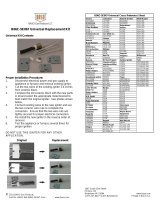
Height
23
in
(584
mm)
Width
15-1/2
in
(394
mm)
Depth
26-1/8
in
(664
mm)
A
24-1/16
in
(611
mm)
B
20-3/4
in
(527
mm)
C
12-3/Bin(314mm)
D
9/32
in
(7
mm)
Dia
Weight
2-1.
Selecting
A
Location
Movement
LocatIon
And
Airflow
OR
4
18
in
(460
mm)
2-2.
Dimensions
And
Weights
ST-800
763-A
Dimensions
ct
~
:Holes
Net:
165
lbs
(75
kg)
Ship:
175
lbs
(79
kg)
OM-167
302
Page
4

2-3.
Weld
Output
Terminals
And
Selecting
Cable
Sizes
Weld
Output
Terminals
Welding
Amperes
Total
Cable
(Copper)
Length
In
Weld
Circuit
Not
Exceeding
100
ft
(30
m)
Or
Less
150ft
(45
m)
200ft
(60
m)
250ft
(70
m)
300ft
(90
m)
350ft
(105
m)
1400ft
(120
m)
1060%
Duty
Cycle
60100%
Duty
Cycle
10
100%
Duty
Cycle
100
4
4
4
3
2
1
1/0
1/0
150
3 3 2
1
1/0
2/0 3/0
3/0
200
3
2
1
1/0
2/0
3/0
4/0
4/0
250
2
1
1/0
2/0
3/0
4/0
2-2/0
2-2/0
300
1
1/0
2/0
3/0
4/0
2-2/0
2-3/0
2-3/0
400
350
1/0
1/0
2/0
2/0
3/0
3/0
4/0
4/0
2-2/0
2-2/0
2-3/0
2-3/0
2-4/0
2-3/0
24/0
2-4/0
Positive
Negative
(+)
()
sers
Guide
vlnections.
500
2/0
3/0
4/0
2-2/0
2-3/0
2-4/0
3-3/0
3-3/0
600
3/0
4/0
2-2/0
2-3/0
2-4/0 3-3/0
3-4/0
3-4/0
700
4/0
2-2/0
2-3/0 2-4/0 3-3/0 3-4/0
3-4/0
4-4/0
800
4/0
2-2/0
2-3/0
2-4/0
3-4/0
3-4/0
4-4/0
4-4/0
Weld
cable
size
(AWG)
is
based
on
either
a
4
volts
or
less
drop
or
a
current
density
of
at
least
300
circular
mils
per
ampere.
s-0007-D
2-4.
Voltage
Sensing
Terminal
Connections
The
voltage
sensing
terminals
pro
vide
exact
voltage
measurement
at
the
welding
arc.
Strip
1/2
in
(13
mm)
insulation
1
Positive
(+)
Voltage
Sensing
Terminal
2
Negative
()
Voltage
Sensing
Terminal
3
Receptacle
c
4
Proper
Plug
(Not
Supplied)
5
18
Gauge
Lead
(Not
Supplied)
6
Nut
7
Lead
Hole
For
Electrode
Positive
(DCEP),
~
connect
remaining
end
of
negative
()
terminal
lead
to
work.
Connect
remaining
end
of
positive
(+)
termi
nal
lead
to
weld
cable
conductor
at
electrode
holder
end
of
weld
cable.
~
For
Electrode
Negative
(OCEN),
reverse
terminal
lead
connections.
ooo
~
Tools
Needed:
~
Ref.
sT-BOO
764/
Ref.
ST-152 885A
I
L
OM-167
302
Page
5

2-5.
Remote
14
Receptacle
Information
24
VOLTS
AC
()~p~
OUTPUT
(CONTACTOR)
A
24
volts
ac.
Protected
by
circuit
breaker
CB2.
B
Contact
closure
to
A
completes
24
volts
ac
contactor
control
circuit.
REMOTE
OUTPUT
CONTROL
C
Command
reference;
+10
volts
dc
in
CV,
0
to
+10
volts
dc
in
CC.
D
Remote
control
circuit
common.
E
0
to
+10
volts
dc
input
command
signal
from
remote
control.
A/V
AMPERAGE
VOLTAGE
H
Voltage
feedback;
+1
volt
dc
per
10
arc
volts.
115
VOLTS
AC
OUTPUT
(CONTACTOR)
I
J
115
volts
ac.
Protected
by
circuit
breaker
CB1.
Contact
closure
to
I
completes
115
volts
ac
contactor
control
The
remaining
sockets
are
not
used.
2-6.
Remote
17
Receptacle
Information
The
remaining
sockets
are
not
used.
OUTPUT
(CONTACTOR)
D
Contactor
on/off
signal;
+13
to
+24
volts
dc
contactor
on,
0
volts
dc
contactor
off.
REMOTE
OUTPUT
CONTROL
A
+10
volts
dc
output
to
remote
control;
allows
full
control
of
A/V
output
from
remote
control.
B
0
to
+10
volts
do
input
command
signal
from
remote
control.
H
+24
volts
dc;
fused
at
1
ampere.
K
0
to
+10
volts
dc
output
to
remote
control
set
by
panel
A/V
con
trol;
allows
percent
of
panel
A/V
control
from
remote
control.
L
24
volts
dc;
fused
at
1
ampere.
Bib.
CV/CC
C
CV/CC
select;
+13
to
+24
volts
do
selects
CV,
0
volts
dc
selects
CC.
~
G
Dig/inductance
control;
0
to
+10
volts
do
set
by
panel
Dig/
Inductance
control.
A
~
AMPERAGE
~~1
~
VOLTAGE
E
Current
feedback;
1
volt
per
100
amperes.
M
Voltage
feedback;
1
volt
per
10
arc
volts.
P
Circuit
common
for
sockets
H
and
L.
REMOTE
14
Socket*
Socket
Information
Ret.
ST-800
784
GND
K
Chassis
common.
G
Circuit
common
for
24
and
115
volts
ac
circuits.
REMOTE
17
Socket*
Socket
Information
Ret.
ST.800
764
GND
F
Circuit
common
for
sockets
A,
B,
0,
E,
K,
and
M.
S
Chassis
common.
OM-167
302
Page
6

2-7.
115
Volts
AC
Twistlock
Receptacle
Input
Voltage
380 415
Input
Amperes
At
Rated
Output
29
27
Max
Recommended
Standard
Fuse
Or
Circuit
Breaker
Rating
In
Amperes
50 45
Mm
input
Conductor
Size
in
AWGIKcm1I
8 8
Max
Recommended
Input
Conductor
Length
In
Feet
(Meteirs)
219(67)
261
(79)
Mm
Grounding
Conductor
Size
In
AWGIKcmII
10 10
Reference:
1993
National
Electrical
Code
(NEC).
s-0092J
2-8.
Electrical
Service
Guide
M-167
302
Page
7

2-9.
Placing
Jumper
Links
And
Connecting
Input
Power
EI~~zJ==n
3/8
in
GND/PE
Earth
Ground
site.
Check
input
voltage
available
at
2
Remove
side
panel.
1
Jumper
Link
Label
2
Jumper
Links
Move
jumper
links
to
match
input
voltage.
3
Input
And
Grounding
Conductors
Select
size
and
length
Section
2-8.
using
4
Line
Disconnect
Device
Select
type
and
size
of
overcurrent
protection
using
Section
2-8.
Reinstall
side
panel.
A
Special
installation
may
be
required
where
gasoline
or
volatile
liquids
are
present
see
NEC
Article
511
or
CEC
Section
20.
3
Tools
Needed:
=r===c
i~
7/16
in
ST-SOS
767A
/
Ref.
ST-801
116
OM-167
302
Page
8

SECTION
3-
OPERATION
3-1.
Symbols
And
Definitions
On
Q
Off
._~3
Power
Over
Temperature
Dig
Inductance
SMAW
~
GTAW
~j
14
Remote
14
0
Panel
~3
Output
GMAW
~J
17
3-2.
Controls
Switch
selects
type
of
weld
output.
Use
SMAW
position
for
SMAW.
Use
GTAW
posi
tion
for
GTAW,
GMAW-P,
and
CAC-A. Use
GMAW
position
for
GMAW,
and
FCAW
(see
Users
Guide).
5
AmperageNoltage
Control
Switch
Switch
selects
panel
On
or
remote
control
of
output
On/Off.
A
Weld
output
terminals
are
energized
when
Output
switch
Is
On
and
Power
Is
On.
7
Arc
Force/Inductance
Control
Switch
Switch
selects
panel
or
remote
control
of
arc
force/inductance.
8
Dig/Inductance
Control
Control
adjusts
dig
with
process
switch
in
SMAW
position.
When
set
towards
0
(zero),
short-circuit
amperage
at
low
arc
voltage
is
the
same
as
normal
welding
amperage.
When
set
towards
100,
short-circuit
amper
age
is
increased
at
low
arc
voltage
to
assist
with
arc
starts
as
well
as
reduce
sticking
while
welding.
Control
adjusts
inductance
with
process
switch
in
GMAW.
Inductance
determines
the
wetness
of
the
weld
puddle.
When
set
towards
100,
wetness
(puddle
fluidity)
increases.
This
control
is
not
functional
with
process
switch
in
GTAW.
Numbers
around
control
are
for
reference
only.
9
High
Temperature
Shutdown
Light
1
Power
Switch
Switch
selects
panel
or
remote
control
of
2
Digital
Meters
amperage/voltage
level.
3
AmperageNoltage
Adjustment
Control
6
Output
(Contactor)
Control
Switch
Control
adjusts
voltage
with
process
switch
in
GMAW
position,
and
adjusts
amperage
in
SMAW
and
GTAW
positions.
Set
control
at
0
for
normal
welding
amper
age.
Turn
clockwise
to
increase
short-cir
cuit
amperage.
4
Process
Switch
OM-167
302
Page
9

0)
3-3.
Duty
Cycle
And
Overheating
.
~.
--..
C,)
4U~
w
____
<
2~
I)
~)
25
~!0
40
~W7O60~W
X
DUTY
CYCLE
Overheating
Duty
Cycle
is
percentage
of
10
minutes
that
unit
can
weld
at
rated
load
without
overheating.
If
unit
overheats,
thermostat(s)
opens,
output
stops,
and
cooling
fan
runs.
Wait
fifteen
minutes
for
unit
to
cool.
Reduce
amperage
or
duty
cycle
before
welding.
A
Exceeding
duty
cycle
can
damage
unit
and
void
war
ranty.
Example:
100%
Duty
Cycle
=
Continuous
Welding
4-1.
Routine
Maintenance
SECTION
4-
MAINTENANCE
&
TROUBLESHOOTING
OM-167
302
Page
10

4-2.
Measuring
Input
Capacitor
Voltage
OM-167
302
Page
11

4-3.
Circuit
Breakers
And
Fuses
Tools
Needed:
cE~zJ=in
3/8
in
Turn
Off
welding
power
source,
disconnect
input
power,
and
check
voltage
on
input
capacitors
ac
cording
to
Section
4-2
before
proceeding.
1
Circuit
Breaker
CB1
If
CB1
opens,
remote
devices
using
115
volts
from
Remote
14
receptacle
stop.
Manually
reset
CB1.
2
Circuit
Breaker
CB2
If
CB2
opens,
remote
devices
using
24
volts
from
Remote
14
receptacle
stop.
Manually
reset
CB2.
3
Circuit
Breaker
CB3
If
CB3
opens,
devices
connected
to
the
115
volt
twistlock
receptacle
stop.
Manually
reset
CB3.
4
Fuse
Fl
Fl
protects
the
control
circuitry
from
overload.
If
Fl
opens,
the
welding
power
source
shuts
down.
5
Fuse
F3
6
Fuse
F4
F3 and
F4
protect
Control
Board
PCi.
If
either
fuse
opens,
remote
control
devices
connected
to
Remote
17
receptacle
RC1
may
shut
down.
See
Parts
List
for
fuse
ratings.
Use
proper
tool
when
removing
fuses.
ST.800
768-Al
Ref.
sT-i
52
069-C/ST-i
50
173-C
OM-167
302
Page
12

4-4.
Troubleshooting
Trouble
Remedy
No
weld
output;
unit
completely
mop-
erative.
Place
line
disconnect
switch
in
On
position
(see
Section
2-9).
Check
fuse
Fl,
and
replace
if
necessary
(see
Section
4.3).
Check
and
replace
line
fuse(s),
if
necessary,
or
reset
circuit
breaker
(see
Section
2-9).
Check
for
proper
input
powe
,~onnections
(see
Section
2-9).
Check
for
proper
jumper
link
position
(see
Section
2-9).
No
weld
output;
Power
switch
on;
fan
on.
If
using
remote
control,
place
Output
(Contactor)
switch
in
Remote
17/14
position,
and
connect
remote
control
to
Remote
14
or
Remote
17
receptacle
(see
Sections
2-5
and
2-6).
If
remote
is
not
being
used,
place
Output
(Contactor)
switch
in
On
position.
Check,
repair,
or
replace
remote
control.
Unit
overheated.
Allow
unit
to
cool
with
fan
On
(see
Section
3-3).
Have
Factory
Authorized
Service
Station/Service
Distributor
check
unit.
Low
weld
output
with
no
control.
.
Check
position
of
A
~ieNoItage
Control
switch.
Have
Factory
Authe
-3r~.;~e
Station/Service
Distributor
check
control
board
PCi.
Limited
output
and
low
open-circuit
voltage,
Check
incoming
power
ior
correct
voltage.
Check
and
replace
line
fuse(s),
if
necessary,
or
reset
circuit
breaker
(see
Section
2.9).
Check
for
proper
jumper
link
position
(see
Section
2-9).
Check
for
proper
input
and
output
connections
(see
Section
2-9).
Erratic
or
improper
weld
output.
Use
proper
size
and
type
of
weld
cable
(see
Section
2-3).
Clean
and
tighten
all
weld
connections.
Check
for
proper
input
and
output
connections
(see
Section
2-9).
Replace
electrode.
Remote
device
completely
inoperative.
.
Check
remote
control
connections
(see
Sections
2-5
and
2-6).
If
remote
device
connected
to
Remote
14
receptacle,
reset
circuit
breaker
CB1,
CB2,
and/or
CB3
(see
Section
4-3)
If
remote
device
connected
to
Remote
17
receptacle,
check
fuses
F3
and/or
F4
and
replace
If
need
ed
(see
Section
4-3).
Fan
not
operating.
Check
for
and
remove
anything
blocking
fan
movement.
Have
Factory
Authorized
Service
Station/Service
D:.~iibutor
check
fan
motor.
No
115
volts
ac
output
at
Remote
14
receptacle.
Reset
circuit
breaker
CB1
(see
Section
4-3).
No
24
volts
ac
output
at
Remote
14
receptacle.
Resetcircuit
breaker
CB2
(see
Section
4-3).
No
115
volts
ac
output
at
twistlock
receptacle.
Reset
circuit
breaker
CB3
(see
Section
4-3).
OM-167
302
Page
13

1E2
LI
L2
U
O~7
SECTIQN
5-
ELECTRICAL
DIAGRAMS
IC
,
I
~
>1-
I
C
<(RC3I-2
14PFI
f~CEPTA~~E
24V.
IB~T.
I
~TACTtR
a
B>
RC3OII
IT~/rN
~~-<
RC31-6
57
H
>
I~3O-Q
>>
I
c
>
(<RC3I-4
>~_~:~
I
C
>
42<<~
r
L~v~
J
I
I
I
I
ill
r*;;\r
I
II
2
3
4
1~~LLJ
II
Q
I
1~
1ev.
17Pt4
C
~c~TAct1
Figure
5-1.
Circuit
Diagram
For
Welding
Power
Source
OM-167
302
Page
14

SI.
O68~j
~OC
L9I.-V~IO
9-ISO
g9~-aS
3N1V~
3NIJSOd
.v
t
i~
v
i
I
S
I,

N
U)
D)
U-
SECTION
6-
PARTS
LIST
0
a)
CD
N
U-
0)
N
0
N
0)
cv)
~
~O
N2)
U-
0)
0
~)
N
~)
N
.0)
CD
U-
a)
a)
a)
U)
a)
0)
N
Ca
E
a,
C
a)
(1)
ST-800
769-A
Figure
6-1.
Main
Assembly
N
CD
N
0
0)
OM-1
67302
Page
16

...3....C50,51....
...6
TE2
TEl
...8
Z3
11
13
RC3
12
PLG11
...26
RC11
...27
Zi
...28
Z2
GB-li
...32
155
652
164
812
126
026
145
743
147
386
038
861
601
219
165
857
166
074
143731
153
178
604
126
143
732
144
929
088 058
135291
166
045
166
680
113
633
145
477
166
679
113
633
144
050
147
901
167742
166017
139
151
605
538
166
551
166
550
148001
Figure
6-1.
Main
Assembly
+When
ordering
a
component
originally
displaying
a
precautionary
label,
the
label
should
also
be
ordered.
BE
SURE
TO
PROVIDE
MODEL
AND
SERIAL
NUMBER
WHEN
ORDERING
REPLACEMENT
PARTS.
Item
Dia.
No.
Mkas.
Part
No.
Description
1
152346
155653
2
+147962
Quantity
17
+166051
Fig6-5
19
605603
20
143741
070592
...22
Fig6-3
...23
Fig6-4
24
145053
COVER,
top
w/insuilation
(consisting
of)
1
INSULATOR,
top
1
PANEL,
side
RH
w/insulator
(consisting
of)
1
INSULATOR,
side
RH
1
CAPACITOR
2
LABEL,
warning
general
precautionary
2
LUG,
univ
w/scr
6ODV
2-14
wire
.250
stud
1
BLOCK,
term
70A
3P
1
BLOCK,
term
20A
3P
1
LINK,
jumper
term
blk
20A
1
BRACKET,
mtg
term
block
1
REACTOR,
line
1
LIFT
EYE,
upright
1
LABEL,
warning
exploding
parts
can
seriously
injure
2
SCREW,
.500-13
x
1
.000hexhd
stl
1
LIFTEVE
1
GASKET,
lift
eye
1
NUT,
.500-13
stl
elastic
stop
1
RECEPTACLE,
twlk
grd
2P3W
15A
250V
1
PANEL,
rear
1
FAN
MOTOR/MOUNTING
BRACKET
1
TUBING,
gI
acryl
1.000-1.036
ID
(order
by
ft)
3ft
SPACER
4
TUBING,
gI
acryl
.500-.524
ID
(order
by
if)
2ft
CHASSIS,
mid
lower
1
CHASSIS,
mid
upper
1
WASHER,
shldr
.2C)3
ID
nyl
12
TRANSFORMER,
kVA
1.5
115-230/380/415-18/18-24
1
CONNECTOR
&
PINS,
(consisting
of)
1
CONNECTOR,
rect
pin
20-l4ga
12
STIFFENER,
base
2
CONNECTOR
&
PINS,
(consisting
of)
1
CONNECTOR,
rect
pins
20-i4ga
12
STABILIZER,
left
1
STABILIZER,
right
1
BUS
BAR,
capacitor
4
BUS
BAR,
capacitor
2
CAPACITOR,
elctlt
2700uf
350V0C
4
CABLE
TIE,
0-4.500
bundle
8
INSULATOR,
capacitor
2
BRACKET,
mtg
capacitor
2
EDGE
TRIM,
style
62-3/32
(order
by
ft)
2ft
..BASE
1
TRANSFORMER,
HF
1
PANEL,
front
w/components
1
LABEL,
warning
general
precautionary
2
PANEL,
side
LH
w/insulator
(consisting
of)
1
INSULATOR,
side
LH
1
LABEL,
warning
electric
shock
can
kill
(on
LH
panel)
1
CONNECTOR
&
SOCKETS
(consisting
of)
1
CONNECTOR,
rect
skt
20-l4ga
3
CONNECTOR
&
SOCKETS,
(consisting
of)
1
CONNECTOR,
rectskt2o-l4ga
6
CONNECTOR
&
PINS,
(consisting
of)
1
CONNECTOR,
rect
pin
20-l4ga
6
36
+165859
37
Ti
166099
Fig6-2
39
134327
40
+147961
155651
149194
PLG21
....
168165
114066
PLG15
....
135556
114066
RC15
116045
113
633
OM-167
302
Page
17

12
3
30
29
ST-800
770-A
Figure
6-2.
Panel,
Front
w/Components
--~
37
7
8
9
10
11
12
13
14
27
34
33
18
19
-~
25
28
27
28
31
24
OM-167
302
Page
18
/