Page is loading ...

COPYRIGHT © MARCH, 2015 BY GRIZZLY INDUSTRIAL, INC.
WARNING: NO PORTION OF THIS MANUAL MAY BE REPRODUCED IN ANY SHAPE
OR FORM WITHOUT THE WRITTEN APPROVAL OF GRIZZLY INDUSTRIAL, INC.
#BB17280 PRINTED IN CHINA
MODEL T10874
RECIPROCATING SAW
OWNER'S MANUAL
(For models manufactured since 01/15)
V1.03.15
This manual provides critical safety instructions on the proper setup,
operation, maintenance, and service of this machine/tool. Save this
document, refer to it often, and use it to instruct other operators.
Failure to read, understand and follow the instructions in this manual
may result in fire or serious personal injury—including amputation,
electrocution, or death.
The owner of this machine/tool is solely responsible for its safe use.
This responsibility includes but is not limited to proper installation in
a safe environment, personnel training and usage authorization,
proper inspection and maintenance, manual availability and compre-
hension, application of safety devices, cutting/sanding/grinding tool
integrity, and the usage of personal protective equipment.
The manufacturer will not be held liable for injury or property damage
from negligence, improper training, machine modifications or misuse.
Some dust created by power sanding, sawing, grinding, drilling, and
other construction activities contains chemicals known to the State
of California to cause cancer, birth defects or other reproductive
harm. Some examples of these chemicals are:
• Lead from lead-based paints.
• Crystalline silica from bricks, cement and other masonry products.
• Arsenic and chromium from chemically-treated lumber.
Your risk from these exposures varies, depending on how often you
do this type of work. To reduce your exposure to these chemicals:
Work in a well ventilated area, and work with approved safety equip-
ment, such as those dust masks that are specially designed to filter
out microscopic particles.
Model T10874 (Mfd. Since 01/15) -1-
SECTION 1: SAFETY
For Your Own Safety Read Instruction Manual
Before Operating This Equipment
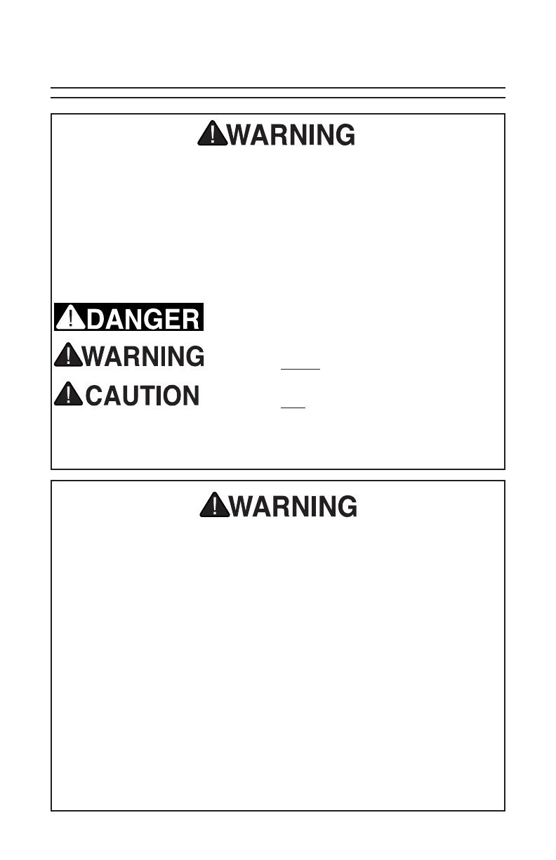
The purpose of safety symbols is to attract your attention to possible hazard-
ous conditions. This manual uses a series of symbols and signal words which
are intended to convey the level of importance of the safety messages. The
progression of symbols is described below. Remember that safety messages by
themselves do not eliminate danger and are not a substitute for proper accident
prevention measures.
Indicates an imminent hazardous situation which, if
not avoided, WILL result in death or serious injury.
Indicates a potentially hazardous situation which, if
not avoided, COULD result in death or serious injury.
Indicates a potentially hazardous situation which, if
not avoided, MAY result in minor or moderate injury.
It may also be used to alert against unsafe practices.
This symbol is used to alert the user to useful infor-
mation about proper operation of the equipment.
NOTICE
Safety Instructions for Power Tools
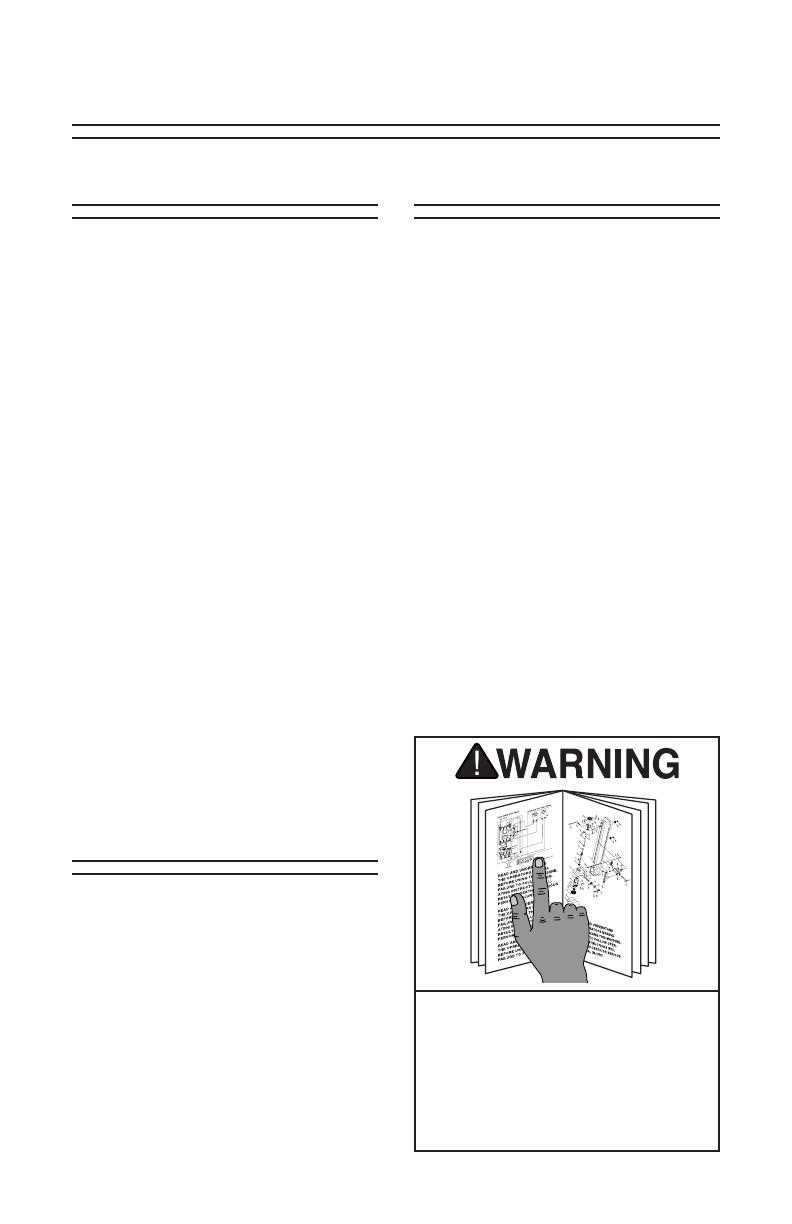
OWNER’S MANUAL. Read and under-
stand this owner’s manual BEFORE using
machine.
TRAINED OPERATORS ONLY. Untrained
operators have a higher risk of being hurt
or killed. Only allow trained/supervised
people to use this power tool. When tool
is not being used, disconnect power, and
store in out-of-reach location to prevent
unauthorized use—especially around
children. Make workshop kid proof!
DANGEROUS ENVIRONMENTS. Do not
use tools in areas that are wet, cluttered,
or have poor lighting. Operating tools in
these areas greatly increases risk of acci-
dents and injury.
MENTAL ALERTNESS REQUIRED. Full
mental alertness is required for safe oper-
ation of power tools. Never operate under
the influence of drugs or alcohol, when
tired, or when distracted.
DISCONNECT POWER FIRST. Always
disconnect tool from power supply
BEFORE making adjustments, chang-
ing tooling, or servicing machine. This
prevents an injury risk from unintended
startup or contact with live electrical com-
ponents.
EYE PROTECTION.
Always wear ANSI-
approved safety glasses or a face shield
when operating or observing machinery to
reduce the risk of eye injury or blindness
from flying particles. Everyday eyeglasses
are not approved safety glasses.

Model T10874 (Mfd. Since 01/15)-2-
ELECTRICAL SAFETY. Tool plug must
match outlet. Double-insulated tools have
a polarized plug (one blade is wider than
the other), which must be plugged into a
polarized outlet. Never modify plug. Do
not use adapter for grounded tools. Use
a ground fault circuit interrupter if opera-
tion is unavoidable in damp locations.
Avoid touching grounded surfaces when
operating tool.
WEARING PROPER APPAREL. Do not
wear clothing, apparel or jewelry that
can become entangled in moving parts.
Always tie back or cover long hair. Wear
non-slip footwear to avoid accidental
slips, which could cause loss of workpiece
control. Wear hard hat as needed.
HAZARDOUS DUST. Dust created while
using tools may cause cancer, birth
defects, or long-term respiratory damage.
Be aware of dust hazards associated with
each workpiece material, always wear
a NIOSH-approved respirator, and con-
nect tool to an appropriate dust collection
device to reduce your risk.
HEARING PROTECTION. Always wear
hearing protection when operating or
observing loud machinery. Extended
exposure to this noise without hearing
protection can cause permanent hearing
loss.
REMOVE ADJUSTING TOOLS. Never
leave adjustment tools, chuck keys,
wrenches, etc. in or on tool—especially
near moving parts. Verify removal before
starting!
INTENDED USAGE. Only use tool for its
intended purpose. Never modify or alter
tool for a purpose not intended by the
manufacturer or serious injury or death
may result!
AWKWARD POSITIONS. Keep proper
footing and balance at all times when
operating tool. Do not overreach! Avoid
awkward hand positions that make tool
control difficult or increase the risk of
accidental injury.
SAFE HANDLING. Firmly grip tool. To
avoid accidental firing, do not keep finger
on switch or trigger while carrying.
FORCING TOOLS. Use right tool for job,
and do not force it. It will do job safer and
better at rate for which it was designed.
SECURING WORKPIECE. When
required, use clamps or vises to secure
workpiece. This protects hands and frees
both of them to operate tool.
GUARDS & COVERS. Guards and cov-
ers reduce accidental contact with mov-
ing parts or flying debris. Ensure they
are properly installed, undamaged, and
working correctly.
CHILDREN & BYSTANDERS. Keep chil-
dren and bystanders at a safe distance
from the work area. Stop using tool if they
become a distraction.
USE RECOMMENDED ACCESSORIES.
Consult this manual or manufacturer
for recommended accessories. Using
improper accessories will increase risk of
serious injury.
MAINTAIN WITH CARE. Keep cutting
tool edges sharp and clean. Follow all
maintenance instructions and lubrication
schedules to keep tool
in good work-
ing condition. A tool that is improperly
maintained could malfunction, leading to
serious personal injury or death. Only
have tool serviced by qualified service-
personnel using matching replacement
parts.
CHECK DAMAGED PARTS. Regularly
inspect tool for any condition that may
affect safe operation. Immediately repair
or replace damaged or mis-adjusted parts
before operating tool.
MAINTAIN POWER CORDS. When dis-
connecting cord-connected tools from
power, grab and pull the plug—NOT the
cord. Carrying or pulling the cord may
damage wires inside. Do not handle cord/
plug with wet hands. Avoid cord damage
by keeping it away from heated surfaces,
high traffic areas, harsh chemicals, sharp
edges, moving parts, and wet/damp loca-
tions. Damaged cords increase risk of
electrocution.
UNATTENDED OPERATION. Never
leave tool running while unattended. Turn
tool OFF and ensure all moving parts
completely stop before walking away.
EXPERIENCING DIFFICULTIES.
If at
any time you experience difficulties per-
forming the intended operation, stop
using the machine! Contact our Technical
Support at (570) 546-9663.

Model T10874 (Mfd. Since 01/15) -3-
No list of safety guidelines can be
complete. Every shop environment
is different. Always consider safety
first, as it applies to your individual
working conditions. Use this and
other machinery with caution and
respect. Failure to do so could result
in serious personal injury, damage to
equipment or poor work results.
Additional Safety Instructions for
Reciprocating Saws
SAFE WORK ENVIRONMENT. Clear
the work area of all parts and debris that
may cause injury by flying objects.
SECURING WORKPIECE. Secure
workpiece in a vise or work holding
device. Do not attempt to hold the
workpiece by hand.
OVERLOADING SAW. Do not apply
excessive pressure to the tool while
in use. If the speed drops abnormally,
decrease pressure immediately.
TOOL INSPECTION. Run the tool free
of the workpiece before using to ensure
all parts are running smooth and there
are no abnormal sounds or sparks. If
any defect is found, have the unit ser-
viced.
REMOVING BLADES. Wear gloves to
protect your hands when removing the
blade to avoid injury.
CHECKING WORKSITE. Make sure
the workpiece is not supporting another
structure and that there are no obstruc-
tions. Before cutting into walls, check
for wires, other electrical hazards, or
plumbing which may be hidden in the
wall space.
SECURING BLADE. Make sure the
blade locking screw is secured before
operating the reciprocating saw so the
blade does not loosen or fly out, which
could cause serious injury.
KEEP BLADES SHARP. Do not use dull
or damaged blades. They may break
or cause the workpiece to be expelled
toward the operator at high speed, caus-
ing serious injury. Replace dull blades
immediately.
TRIGGER LOCK. Make sure the trig-
ger lock is in the OFF position before
shutting the reciprocating saw OFF, or
before turning it ON.

Model T10874 (Mfd. Since 01/15)-4-
Understanding
Kickback
Preventing Kickback
Kickback is a sudden and unexpected
expulsion of the saw from the workpiece,
which can violently propel the saw back
toward the operator, resulting in accidental
blade contact or impact injury.
Kickback is caused when the saw blade
becomes misaligned, pinched, bound, or
comes in contact with a material it is
unable to cut. When kickback occurs, the
saw blade becomes immediately immo-
bile. The force produced by the motor is
diverted from the blade and transferred
to the saw, pushing it up and away from
the workpiece and potentially toward the
operator.
The lack of warning and high risk of injury
from kickback makes it extremely impor-
tant to: (1) reduce the risk of kickback, and
(2) protect yourself in case it does occur.
Take these precautions to help prevent
the most common causes of kickback:
• Hold saw firmly with both hands and
position arms to help resist kickback
forces. Always stand to one side of saw
when operating—never directly behind
it. When kickback does occur, it will
eject the saw back toward the operator.
• Support large panels, making sure sup-
ports are positioned under both sides of
the cutting line.
• Allow blade to reach full speed before
starting the cut.
• To help prevent the blade from bind-
ing in the workpiece: (1) keep cuts
straight, (2) maintain a consistent depth
and angle throughout cut, (3) provide
proper workpiece support on both sides
of the cut.
• Follow cuts through to completion
whenever possible. If a cut must be
stopped before completion or the
blade begins to bind, release the ON/
OFF trigger and hold the saw motion-
less while the blade comes to a com-
plete stop before removing it from
the workpiece. When resuming the
cut, center your blade in the kerf and
ensure that the teeth are not touching
the workpiece.
• Only use sharp, clean, undamaged
blades. Dull blades create much more
friction and resistance while cutting,
which greatly increases the risk of kick-
back.
Model T10874 (Mfd. Since 01/15) -5-
SECTION 2: INTRODUCTION
We are proud to offer this manual with your
new T10874 Reciprocating Saw! We've
made every effort to be exact with the
instructions, specifications, drawings, and
photographs of the T10874 Reciprocating
Saw we used when writing this manual.
However, sometimes we still make an
occasional mistake.
Also, owing to our policy of continuous
improvement, your T10874 Reciprocating
Saw may not exactly match the manual.
If you find this to be the case, and the dif-
ference between the manual and T10874
Reciprocating Saw leaves you in doubt,
check our website for the latest manual
update or call technical support for help.
For your convenience, we post all avail-
able manuals and manual updates for free
on our website at www.grizzly.com. Any
updates to your model of machine will be
reflected in these documents as soon as
they are complete.
Foreword Contact Info
We stand behind our machines. If you
have any service questions, parts requests
or general questions about the machine,
please call or write us at the location listed
below.
Grizzly Industrial, Inc.
1203 Lycoming Mall Circle
Muncy, PA 17756
Phone: (570) 546-9663
E-Mail: techsupport@grizzly.com
We want your feedback on this manual.
If you can take the time, please email or
write to us at the address below and tell
us how we did:
Grizzly Industrial, Inc.
C/O Technical Documentation Manager
P.O. Box 2069
Bellingham, WA 98227-2069
Email: manuals@grizzly.com
Specifications
Read the manual before operation.
Become familiar with this tool, its
safety instructions, and its operation
before beginning any work. Serious
personal injury may result if safety or
operational information is not under-
stood or followed.
Weight .......................................... 5.5 lbs.
Horsepower ........................... 720W (1HP)
Voltage ..............................................120V
Phase ...................................Single-Phase
Amps .....................................................6A
Speed ................................... 0–2500 SPM

Model T10874 (Mfd. Since 01/15)-6-
Identification
A. Quick-Release Chuck
B. Front Grip
C. Rotation Button
D. Variable-Speed Trigger Switch
E. Trigger Lock Button
F. Rear Grip
G. Motor Brush Cap
H. Pivot Foot Adjustment Bolts
I. Adjustable Pivot Foot
To reduce your risk of
serious injury, read this
entire manual BEFORE
using machine.
Become familiar with the names and locations of the controls and features shown below to
better understand the instructions in this manual.
B
C
D
A
G
G
H
I
F
E

Model T10874 (Mfd. Since 01/15) -7-
Your machine was carefully packaged for
safe transportation. Remove the packag-
ing materials from around your machine
and inspect it. If you discover the machine
is damaged, please immediately call
Customer Service at (570) 546-9663 for
advice.
Save the containers and all packing mate-
rials for possible inspection by the car-
rier or its agent. Otherwise, filing a freight
claim can be difficult.
When you are completely satisfied with
the condition of your shipment, inventory
the contents.
If any non-proprietary parts are missing
(e.g., a nut or a washer), we will gladly
replace them; or for the sake of expedi-
ency, replacements can be obtained at
your local hardware store.
SECTION 3: SETUP
Unpacking Inventory
Model T10874 Inventory (Figures 1–2)
A. Reciprocating Saw .............................1
B. 5" Wood Cutting Blade.......................1
C. 3
1
⁄4" Metal Cutting Blade ....................1
Figure 1. Model T10874.
A
Figure 2. Included blades.
B
C

Model T10874 (Mfd. Since 01/15)-8-
Connecting Power
Power Connection
After you have completed all previous
setup instructions, the machine is ready to
be connected to the power supply.
To avoid unexpected startups or property
damage, use the following steps whenever
connecting or disconnecting the machine.
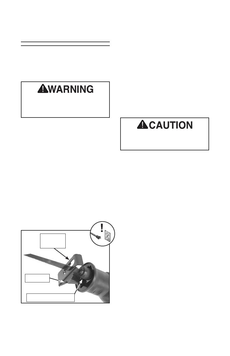
1. Verify trigger lock button is released.
2. Insert power cord plug into a matching
power supply receptacle. Tool is now
connected to power source.
Figure 3. Connecting power.
To test run machine:
1. Clear all setup tools away from
machine.
2. Connect machine to power supply.
3. Pull variable-speed trigger, verify motor
operation, and then release trigger.
Tool should run smoothly and without
unusual problems or noises.
Test Run
Serious injury or death can result
from using this machine BEFORE
understanding its controls and
related safety information. DO NOT
operate, or allow others to oper-
ate, machine until the information is
understood.
1. Verify trigger lock button is released.
2. Grasp molded plug and pull it com-
pletely out of receptacle. Do not pull
by the cord as this may damage wires
inside.
Disconnecting Power
Figure 4. Disconnecting power.
Model T10874 (Mfd. Since 01/15) -9-
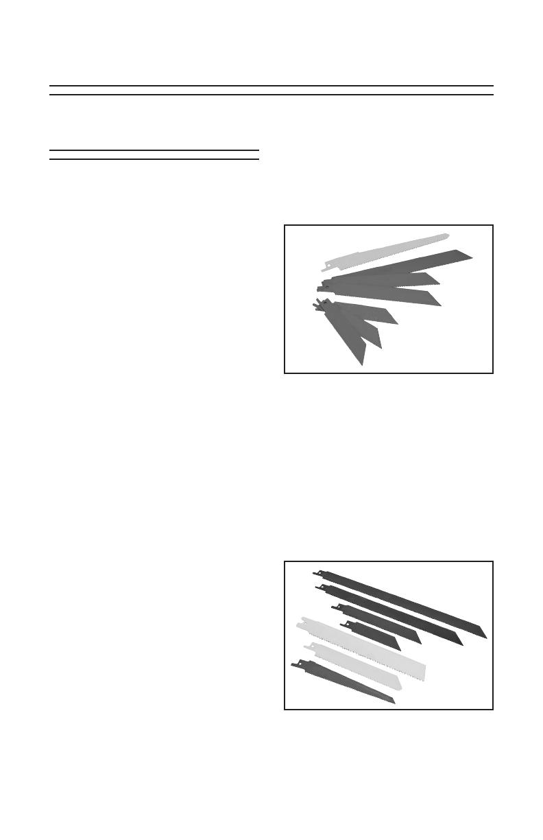
Figure 6. Assortment of rough-cut
reciprocating saw blades.
Figure 5. Assortment of fine-cut
reciprocating saw blades.
SECTION 4: OPERATIONS
Blade Selection
Always use sharp blades and select the
correct saw blade for the material being
cut. The resulting cut will be cleaner and
more accurate, and there will be less stress
on the tool. This reciprocating saw can be
used to cut wood, metal or plastics depend-
ing upon the type of blade selected. Your
reciprocating saw comes with a wood and
metal blade, as listed in the Inventory.
A few points to remember in making
your blade selection:
• The overall blade length will affect the
thickness of material that can be cut.
Most reciprocating saw blades range in
length from 3" to 12".
• The width of the blade (measured from
the tip of one of the teeth to the back
edge of the blade) affects the durabil-
ity and resistance to bending during a
cut. A
7
⁄8" wide blade will be much more
durable than a
3
⁄8" wide blade.
• The number of teeth per inch (TPI)
affects the smoothness and speed of
the cut. A general purpose wood cut-
ting blade will usually have 4–14 TPI;
a metal cutting blade will have 14–24
TPI. Another factor is the tooth style
and how the teeth are set (the amount
the tooth is bent away from the plane of
the blade). Most blade manufacturers
provide guidelines on their packaging
for the types of materials and speeds to
use for a particular blade style. Review
their guidelines carefully before choos-
ing a blade for a particular project.
Fine-cut blades have high TPI and are
designed to produce a smooth cut. They
are generally used for cutting various
types of metal. They come in a variety of
lengths and widths (see Figure 5).
Rough-cut blades have low TPI and are
designed to make quick cuts. They are
generally used for cutting natural and man
made wood materials, drywall, or plastics.
These blades come in a variety of lengths
and widths (see Figure 6).
Fine-Cut Blades
Rough-Cut Blades
Model T10874 (Mfd. Since 01/15)-10-
The Model T10874 uses standard recipro-
cating saw blades. See the Grizzly catalog
or website for a complete listing of avail-
able blades and accessories.
1. DISCONNECT TOOL FROM POWER!
2. Rotate quick-release chuck counter-
clockwise and hold to disengage blade
lock.
3. Insert blade shank into chuck with teeth
pointed towards pivot joint on adjust-
able pivot foot (see Figure 7).
Note: Blade can be inserted upside
down; however, the setup outlined in
Step 3 is generally more stable and
safe.
1. DISCONNECT TOOL FROM POWER!
2. Rotate quick-release chuck counter-
clockwise and hold to disengage blade
lock.
3. Remove blade by gripping smooth side
of blade and pulling away from chuck.
DO NOT use bent or damaged
blades. The blade could break apart
under stresses of high speed use,
causing serious personal injury.
4. Release chuck to engage blade lock.
5. Verify blade is locked in position by
carefully pulling on it.
Saw blade is sharp and will be hot
after use. Wear gloves to prevent
injury when removing blade.
Installing/Removing
Blades
Installing Blades
Removing Blades
Figure 7. Blade inserted into chuck with
teeth pointed towards pivot joint.
Quick-Release Chuck
Adjustable
Pivot Foot
Pivot Joint

Model T10874 (Mfd. Since 01/15) -11-
Adjusting Pivot Foot Adjusting Rotating
Handle
To adjust rotating handle:
1. DISCONNECT TOOL FROM POWER!
2. Press and hold handle rotation button.
The pivot foot can be adjusted to allow
more or less clearance between the tip
of the blade and potential obstacles when
cutting in tight quarters. Extending the
foot effectively shortens the length of the
blade.
The handle rotation can be adjusted 180°
with five separate locking positions to
allow for a secure and comfortable grip—
no matter the cutting angle.
Failure to properly lock handle into
position could result in serious per-
sonal injury.
3. Rotate handle to desired position.
4. Release rotation button.
5. Gently twist handle until it locks into
position.
Figure 9. Press and hold rotation button.
Handle Rotation
Button
To adjust pivot foot:
1. DISCONNECT TOOL FROM POWER!
2. Loosen cap screws located on bottom
of front grip (see Figure 8).
3. Adjust pivot foot to desired clearance.
4. Tighten cap screws.
Figure 8. Loosen cap screws to adjust
pivot foot.
Cap Screws
Adjustable
Pivot Foot

Model T10874 (Mfd. Since 01/15)-12-
Failure to wear safety glasses while
operating the saw could cause seri-
ous personal eye injury.
Keep foot pressed firmly against
workpiece to reduce risk of kickback,
resulting in serious personal injury.
Starting saw with blade touching
workpiece could cause kickback
resulting in serious personal injury.
Operating Reciprocating Saw
Most operations performed with the Model
T10874 will produce the best results at
higher SPM (stroke per minute) settings;
however, slower SPM settings are ideal
when working with plastics that melt easily.
Use low-SPM settings when working
with plastics or other materials with
low melting points. Melted plastics
can liquefy, be thrown into the air,
and stick to the operator, causing
serious personal injury.
Low SPM's are best for cutting materi-
als that have low melting points, such as
plastics.
High SPM Uses
High SPM's are best for general cutting.
The blade removes material more quickly
at higher SPM's.
Low SPM Uses
Saw Operations
General Cutting
Figure 10. Proper position to start cut.
Pivot Foot
1. Install blade and adjust rotating handle.
2. Grasp tool firmly, then pull trigger allow-
ing saw to come up to desired speed.
3. Adjust speed by varying pressure
applied to trigger.
4. Rest pivot foot on workpiece, then ease
blade into workpiece (see Figure 10).
5. Maintain steady cut speed and pivot
foot pressure until cut is complete.
6. Wait for blade to completely stop
before setting tool down.
Model T10874 (Mfd. Since 01/15) -13-
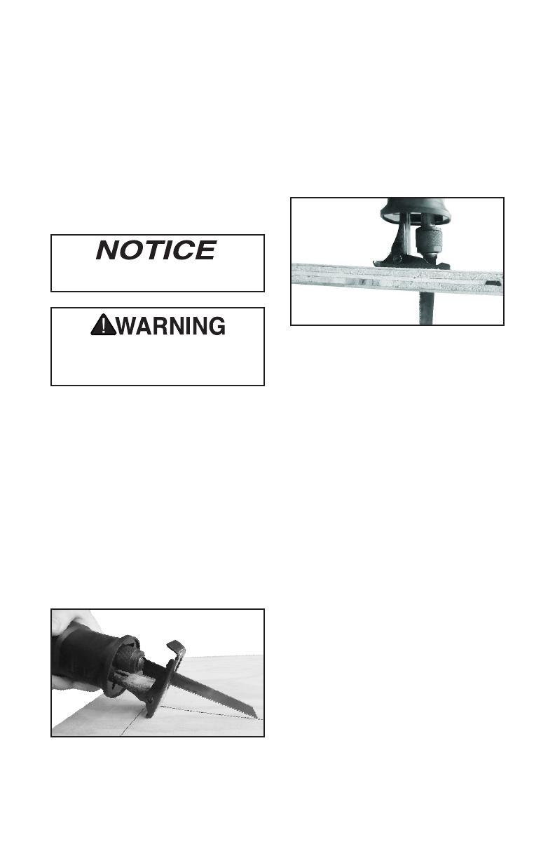
Plunge Cutting
A plunge cut is a sawing operation in which
the cut is started above the workpiece; the
blade engages the workpiece surface by
"plunging" down through it, then advancing
the cut normally. We recommend avoiding
plunge cutting whenever possible due to
an increased risk of kickback or blade
breakage. Drilling a starter hole or using
a more appropriate tool should be used
instead.
2. Hold saw firmly and pull trigger, allow-
ing saw to come up to full speed, then
gradually lower blade tip into panel.
Allow blade to completely penetrate
panel before continuing cut.
3. After blade is through panel (see Figure
12) carefully position pivot foot flush
with workpiece, then finish cut.
Starting saw with blade touching
workpiece could cause kickback,
resulting in serious personal injury.
Plunge cuts should never be per-
formed on metal or hardwoods.
Tip: Depending on work to be performed,
blade can be installed upside down to aid
in plunge cutting.
To perform plunge cut:
1. Place bottom of pivot foot firmly on
workpiece and align tip of blade with
cut line (see Figure 11).
— If blade is installed upside down, use
opposite side of pivot foot.
Figure 11. Plunge cut blade placement.
Figure 12. Plunge cut foot placement.
Cutting Metal
When cutting metal, always begin at a
low SPM and slowly increase speed. This
will increase the accuracy of the cut and
prevent the blade from jumping around on
the surface of the workpiece. Using cut-
ting fluid will prolong blade life and prevent
over-heating.
To cut metal:
1. Install metal cutting blade.
2. Coat workpiece with cutting fluid.
3. Grasp tool firmly, then pull trigger,
allowing saw to come up to desired
speed.
4. Rest pivot foot on workpiece,
then ease blade into workpiece.
(see Figure 10 on Page 12).
5. Maintain steady cut speed and pivot
foot pressure until cut is complete.
6. Wait for blade to completely stop
before setting tool down.

Model T10874 (Mfd. Since 01/15)-14-
SECTION 5: MAINTENANCE
!
Always DISCONNECT POWER
before servicing, adjusting, or
doing maintenance to reduce risk
of accidental injury or electrocution.
Schedule
For optimum performance from your tool,
follow this maintenance schedule and refer
to any specific instructions given in this
section.
Daily Check
• Wipe motor housing, chuck, front grip,
and rear grip with a dry cloth, or blow
off dust and debris with compressed
air (be sure to wear a respirator while
doing this).
• Check for damage to blades, cords,
and housing.
Replacing Carbon Brushes
Carbon brush life is 500–2000 hours,
depending on the nature of use. Always
replace both brushes at the same time.
To replace carbon brushes:
1. Use small flathead screwdriver to
remove caps from sides of motor
housing (see Figure 13).
Note: Brushes are spring loaded; take
care when removing caps.
2. Remove carbon brushes.
3. Install new brushes.
4. Re-install brush cap. Run tool for 5
minutes to seat brushes before using
tool on a workpiece.
Figure 13. Removing motor brush cap and
motor brush (1 of 2).
Carbon Brush
Assembly
Brush Cap

Model T10874 (Mfd. Since 01/15) -15-
Troubleshooting
SECTION 6: SERVICE
Symptom Possible Cause Possible Solution
Tool does not start or a
breaker trips.
1. Wall circuit breaker tripped.
2. Plug/receptacle at fault/
wired wrong.
3. Wiring open/has high resis-
tance.
4. Motor brushes at fault.
5. Motor at fault.
1. Ensure circuit size is cor-
rect/replace weak breaker.
2. Test for good contacts; cor-
rect the wiring.
3. Check/fix broken, discon-
nected, or corroded wires.
4. See Replacing Carbon
Brushes on Page 14.
5. Test/repair/replace.
Tool stalls or is under-
powered.
1. Workpiece crooked; foot
mis-adjusted.
2. Tool undersized for task;
dull blade.
3. Plug/receptacle at fault.
4. Motor bearings at fault.
5. Motor overheated.
6. Motor brushes at fault.
7. Motor at fault.
1. Straighten or replace
workpiece; adjust foot.
2. Reduce feed rate or depth
of cut; replace blade.
3. Test for good contacts/cor-
rect wiring.
4. Test/repair/replace.
5. Clean motor, let cool, and
reduce workload.
6. See Replacing Carbon
Brushes on Page 14.
7. Test/repair/replace.
Tool has excessive
vibration or noisy
operation.
1. Motor or component loose.
2. Blade at fault.
3. Motor bearings at fault.
1. Inspect/replace damaged
bolts/nuts, and re-tighten
with thread locking fluid.
2. Install new blade.
3. Test by rotating shaft;
grinding/loose shaft
requires bearing replace-
ment.
Blade tracks incorrectly 1. Incorrect blade for applica-
tion.
2. Blade is bell-mouthed,
worn, or dull.
1. See Blade Selection on
Page 9.
2. Install new blade.
Cut is crooked or blade
wanders.
1. Blade is dull or damaged.
2. Tooth set is uneven.
1. Install new blade.
2. Install new blade.
Model T10874 (Mfd. Since 01/15)-16-
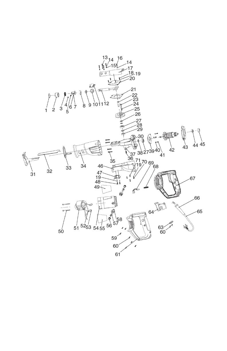
Parts Breakdown

Model T10874 (Mfd. Since 01/15) -17-
Parts List
REF PART # DESCRIPTION REF PART # DESCRIPTION
1 PT10874001 RETAINING RING 36 PT10874036 PHLP HD SCR M5-.8 X 12
2 PT10874002 CHUCK KNOB 37 PT10874037 FENDER WASHER 6MM
3 PT10874003 COMPRESSSION SPRING 38 PT10874038 EXT RETAINING RING 10MM
4 PT10874004 DOWEL PIN 39 PT10874039 MOTOR BEARING RACE
5 PT10874005 COMPRESSION SPRING 40 PT10874040 FLAT WASHER 4MM
6 PT10874006 CHUCK HUB 41 PT10874041 PHLP HD SCR M4-.7 X 8
7 PT10874007 DOWEL PIN 3 X 16MM 42 PT10874042 ROTOR
8 PT10874008 CHUCK BASE, PLASTIC 43 PT10874043 MOTOR FAN ENCLOSURE
9 PT10874009 SHAFT WIPER, FELT 44 PT10874044 BALL BEARING 607ZZ
10 PT10874010 LINEAR BEARING 45 PT10874045 BUSHING
11 PT10874011 BEARING HOUSING 46 PT10874046 GEARBOX SHROUD, LOWER
12 PT10874012 RECIPROCATING SHAFT 47 PT10874047 CLAMPING PLATE
13 PT10874013 PHLP HD SCR M4-.7 X 18 48 PT10874048 CAP SCREW M5-.8 X 14
14 PT10874014 LOCK WASHER 4MM 49 PT10874049 GRIZZLY POWER TOOLS LABEL
15 PT10874015 FLAT WASHER 4MM 50 PT10874050 TAP SCREW M4 X 60
16 PT10874016 PHLP HD SCR M4-.7 X 8 51 PT10874051 STATOR
17 PT10874017 GEARBOX SHROUD, UPPER 52 PT10874052 MOTOR BRUSH CONNECTOR
18 PT10874018 PHLP HD SCR M5-.8 X 10 53 PT10874053 MOTOR BRUSH HOUSING SPRING
19 PT10874019 LOCK WASHER 5MM 54 PT10874054 MOTOR HOUSING
20 PT10874020 GEARBOX ENCLOSURE 55 PT10874055 GRIZZLY ID LABEL
21 PT10874021 GEARBOX SPACER 56 PT10874056 MOTOR BRUSH CAP
22 PT10874022 DRIVE SHAFT 57 PT10874057 MOTOR BRUSH
23 PT10874023 NEEDLE BEARING 7 X 13 X 11MM 58 PT10874058 MOTOR BRUSH HOUSING
24 PT10874024 COUPLER PIN 59 PT10874059 TAP SCREW M4 X 14
25 PT10874025 DRIVE GEAR 60 PT10874060 TAP SCREW M4 X 16
26 PT10874026 FENDER WASHER 10MM 61 PT10874061 LEFT HANDLE
27 PT10874027 BALL BEARING 6000ZZ 63 PT10874063 POWER CORD CLAMP
28 PT10874028 INT RETAINING RING 22MM 64 PT10874064 TRIGGER SWITCH
29 PT10874029 BALL BEARING 608ZZ 65 PT10874065 POWER CORD 18G 2W 72" 1-15P
30 PT10874030 GEARBOX CASTING 66 PT10874066 CORD GUARD
31 PT10874031 PIVOTING FOOT 67 PT10874067 RIGHT HANDLE
32 PT10874032 SAW BLADE 5" 10TPI 68 PT10874068 COMPRESSION SPRING
33 PT10874033 FRONT HANDLE MOUNTING PLATE 69 PT10874069 HOUSING ROTATE BUTTON
34 PT10874034 FRONT HANDLE 70 PT10874070 PHLP HD SCR M5-.8 X 18
35 PT10874035 TAP SCREW M4 X 25 71 PT10874071 PHLP HD SCR M5-.8 X 14

/