Page is loading ...

THANK YOU
We appreciate the trust and con dence you have placed in CE Tech through the purchase of this wall mounting
system. We strive to continually create quality products designed to enhance your home. Visit us online to see our
full line of products available for your home improvement needs. Thank you for choosing CE Tech!
#110384
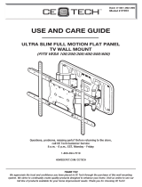
USE AND CARE GUIDE
FIXED FLAT PANEL TV WALL MOUNT WITH HDMI
CABLE AND BUILT-IN LEVEL
(UNIVERSAL MOUNTING PATTERN, FITS VESA 200/300/400/500/600)
Questions, problems, missing parts? Before returning to the store,
call CE Tech Customer Service
8 a.m. - 7 p.m., EST, Monday - Friday, 9 a.m. - 6 p.m., EST, Saturday
PHONE: 01 800 004 6633
HOMEDEPOT.COM/CETECH
IMPORTER: SERVICIOS HOME DEPOT, S. DE R.L. DE C.V.
RICARDO MARGÁIN NO. 605, SANTA ENGRACIA, SAN PEDRO GARZA GARCÍA, NUEVO LEÓN, MÉXICO CP 66267

2
Table of Contents
Safety Information .....................................................2
Warranty.....................................................................2
Pre-Installation ..........................................................3
Installation .................................................................6
Safety Information
Before you begin, make sure you carefully read and
understand the instructions in this manual. This bracket
system incorporates a slip-on mount design. Please
follow the instructions in the order presented in this
manual and observe all warnings and cautions.
WARNING: A Warning alerts you to the possibility of
serious injury or death if you do not follow the instructions.
25.3 in
643mm
24 in
610mm
20 in
508mm
16 in
406.4mm
min 7.87 in-max 24 in
min 200mm-max 610mm
3.93 in
100mm
min 7.87 in-max 15.94 in
min 200mm-max 405mm
16.73 in
425mm
0.984 in
25mm
This mount has been tested to support a television with a
diagonal screen size up to 80 in. (203.2 cm) and a weight
up to 150 lbs (68 kg).
WARNING: This wall mount is intended for use only
with the maximum weights indicated. Use with products
heavier than the maximum weights indicated may result in
collapse of the mount and its accessories causing possible
injury. This mount has been tested to support 150 lbs. (68
kg). Do not exceed this weight.
WARNING: Observe all safety measures at all times
during the installation of this product. Use proper safety
gear and tools during the installation process to prevent
physical injury.
WARNING: Failure to provide adequate structural
strength for this component can result in physical
injury and/or damage to equipment. It is the installer’s
responsibility to make sure the structure to which this
component is attached can support four times the
combined weight of all equipment. Reinforce the structure
as required before installing the component.
CAUTION: Do not install near a heater, replace, direct
sunlight or any other source of direct heat. Doing so
could result in damage to the at panel display and could
increase the risk of re.
CAUTION: Do not install on a structure that is prone to
vibration, movement or chance of impact. Doing so could
result in damage to the at panel display and/or mounting
surface.
CAUTION: A Caution alerts you to the possibility of
damage to or destruction of the equipment if you do not
follow the corresponding instructions.
Warranty
The manufacturer warrants that it will replace or repair this item, free of charge, at the manufacturer’s sole
discretion, should it prove defective in materials or workmanship.
If a claim is made under this warranty, the mount should be returned, freight prepaid, with the original purchase
receipt to your dealer.
This warranty does not apply to:
□ Normal wear and tear
□ Friction damage
□ Coating defects
□ Defects caused by loosened screws, nuts,
or bolts
□ Improperly mounting the bracket to the wall
□ Improperly installing the bracket to the display
□ Failure to properly follow installation instructions
□ Modi cation or repairs not made or authorized by the
manufacturer
□ Loading beyond permitted load
□ Intentional misuse
This warranty information is not valid for Mexico.
Contact the Customer Service Team at 01 800 004 6633 or visit www.HOMEDEPOT.com/CETECH.

3 HOMEDEPOT.com/CETECH
Please contact 01 800 004 6633 for further assistance.
Pre-Installation
PLANNING INSTALLATION
Compare all parts in the package with the Hardware Included and Package Contents lists in this manual. If any part
is missing or damaged, do not install this wall mount system and call customer service at 01 800 004 6633 or visit
www.HomeDepot.com/cetech.
PLANNING WALL PLACEMENT
CAUTION: Ensure the wall you select is a weight-bearing wall. Failure to observe this precaution can result in serious physical injury
and/or property damage. Consult a professional installer or contact customer service if you have any questions.
When selecting a wall to mount your display, keep the following in mind:
□ Select a place with easy access to power outlets, cable input sources, and connections for speakers and
accessories.
□ Avoid direct sunlight, heat, and vibrations and do not place in direct ow of traf c.
□ Select a weight-bearing wall. The wall must be able to safely support four times the combined load of the
equipment and all attached hardware and components.
PLANNING MOUNTING HEIGHT
The optimal viewing height is to center the display at eye level when seated. Many people consider this to be too
low for a wall mount, and commonly use the following rule for placement:
□ Position the bottom of the display no higher than eye level when seated, and the top of the display no higher
than eye level when standing. Anything within these limits should normally provide a comfortable viewing
experience.
ENSURING WALL STABILITY
Carefully inspect the wall area you have selected. Examine the wall surface before you begin drilling.
WARNING: Do not drill near electrical wiring and water pipes.
CAUTION: Wood studs must be no smaller than 2 x 4 in. (5 x 10.16 cm) in size.
□ For concrete walls, check for damaged or loose concrete and do not drill in those areas.
□ For brick wall, never drill into the mortar between blocks.
□ For wood studs, locate the wall studs and drill in the center of the stud.

4
Pre-Installation (continued)
TOOLS REQUIRED (NOT INCLUDED IN THE PACKAGING)
Power drill
5/32 in. (4 mm)
wood drill bit or
1/4 in. (6 mm) +
3/8 in. (10 mm)
masonry drill
bits
Phillips
screwdriver
Stud nder
Measuring
tape
Pencil Hammer
Safety
glasses
HARDWARE INCLUDED
NOTE: Hardware not shown to actual size.
NOTE: The hardware included is suitable for mounting to walls made of brick, solid concrete, or wood studs covered with drywall. If
your mounting situation is different, please consult a quali ed installer or contact customer service at 01 800 004 6633 or visit
www. HomeDepot.com/cetech.
AA
FF GG HH II JJ
BB CC DD EE
Part Description Quantity
AA Lag bolt 4
BB Anchor 4
CC M4 screw 4
DD M5 screw 4
EE M6 screw 4
FF M8 screw 4
GG Spacer 4
HH M4/M5 washer 4
II M6/M8 washer 4
JJ Lag bolt washer 4

5 HOMEDEPOT.com/CETECH
Please contact 01 800 004 6633 for further assistance.
Pre-Installation (continued)
PACKAGE CONTENTS
A
B
Part Description Quantity
A Wall plate 1
B Bracket 2
INCLUDES:
HDMI Cable
Brand: CE TECH
Read the instructions before using this product.
Instruction for HDMI cable connection: Connect component audio / video. Connect according to the particular
speci cations of each product.

6
Installation
1
Installing the wall plate
(wood stud)
If you are installing this mounting system in brick
(concrete), proceed to step 2.
CAUTION: Avoid drilling near electrical wiring and
water pipes. The mounting system must be attached to
a weight bearing wall and must be installed directly onto
the center of the wood studs. Failure to observe all safety
precautions can result in serious physical injury and/or
property damage. Consult a professional installer or call
customer service if you have any questions.
CAUTION: Wood studs must be no samller than 2 x 4 in.
(5 x 10.16 cm) in size.
CAUTION: Gypsum board on masonry wall surface
should be maximum 3/8 in. (10 mm) thick.
□ Use a commercially-available stud nder to
locate the stud centers in the wall. Studs are
usually spaced 16 in. (40.64 cm) apart.
□ Use the wall plate (A) as a template to mark
the installation holes. Use the bubble level (1)
on the wall plate to ensure it is level.
□ Use a 5/32 in. (4 mm) bit to drill 2.2 in. (55
mm) pilot holes.
A
1
2
Installing the wall plate
(concrete/brick walls)
CAUTION: Avoid drilling near electrical wiring and water
pipes. The mounting system must be attached to a weight
bearing wall. Failure to observe all safety precautions can
result in serious physical injury and/or property damage.
Consult a professional installer or call customer service if
you have any questions.
CAUTION: Do not drill in mortar between bricks or into
loose concrete. Never drill into hollow brick.
CAUTION: Never drill into hollow brick.
CAUTION: Concrete wall and brick should be minimum
5.5 in. (13.9 cm) thick.
CAUTION: Gypsum board on masonry wall surface
should be maximum 3/8 in. (10 mm) thick.
□ Use the wall plate (A) as a template to mark
the installation holes. Use the bubble level (1)
on the wall plate to ensure it is level.
□ Use a 1/4 in. (6 mm) masonry drill bit to slowly
drill 2.4 in. (60 mm) pilot holes. Then use a
3/8 in. (10 mm) masonry drill bit to expand the
pilot holes.
□ Insert anchors (BB) into the holes. Ensure the
anchors are completely ush to the concrete
surface even if covered by a layer of joint
compound or other material.
A
BB
BB
1

7 HOMEDEPOT.com/CETECH
Please contact 01 800 004 6633 for further assistance.
Installation (continued)
3
Attaching the wall plate
□ Position the wall plate (A) over the installation
holes. Ensure that the plate is level.
□ Attach the wall plate (A) to the wall using lag
bolts (AA) and washers (JJ). Tighten the bolts
in a criss-cross pattern.
CAUTION: Tighten the lag bolts so that the wall plate is
rmly attached. Do not overtighten. Over-tightening can
damage the screws, greatly reducing the holding power.
A
JJ
AA
4
Identifying the screw diameter
to use
To ensure proper mounting of the brackets to your
TV, this mounting system includes several sizes of
screws (CC through FF) that can be used in various
combinations. Combinations are determined by the
back style of the TV ( at, curved, or recessed) and the
diameter and depth of those holes.
□ Select the screw diameter to use by inserting
the various sized screws provided (M4, M5,
M6, and M8) into the mounting holes in the
back of your TV.
oror or
M5M4 M8M6

8
Installation (continued)
5
Identifying the screw length to
use
□ Insert a straw or toothpick into one of the
mounting holes on the back of your TV. If
your TV is curved or recessed, place the
proper sized spacer (GG) on top of one of the
mounting holes rst. Use a pencil to mark the
depth of the mounting hole.
□ Determine the proper screw length to use by
comparing the mark with the various screws
provided (CC – FF).
CAUTION: When the screw is longer than the mark,
choose a shorter screw.
Flat
Curved
Recessed
6
Removing your TV from the
wall
□ Center the brackets (B) vertically to the back
of the TV.
□ Attach the brackets (B) to the back of the TV
using the properly sized screws and washers
you chose in steps 4 and 5.
CAUTION: Tighten the screws so the brackets are rmly
attached. DO NOT OVERTIGHTEN. This may damage your TV.
□ For M4 and M5 screws (CC and DD), use M4/
M5 washers (HH). For M6 and M8 screws (EE
and FF), use M6/M8 washers (II).
HH-II
CC-FF
CC-DD
B
HH
OR
GG
EE-FF
II
GG

9 HOMEDEPOT.com/CETECH
Please contact 01 800 004 6633 for further assistance.
Installation (continued)
7
Securing the TV to the wall
plate
□ Lower the brackets (B) over the top of the wall
plate (A) until the brackets (B) slide over the
wall plate (A).
□ Press the bottom of the brackets (B) towards
the wall until they snap into place.
CAUTION: Make sure the auto locker is in locking
position before snapping it into the wall plate.
IMPORTANT: Make sure the auto locker is in locking
position before snapping it into the wall plate.
8
Removing the TV from the wall
mount
□ To unlock and remove the TV from the wall,
pull the bottom of the lock straps down, pull
the bottom of the brackets (B) away from the
wall, and carefully lift the TV upwards and off
of the wall plate (A).
A
B

Questions, problems, missing parts? Before returning to the store,
call CE Tech Customer Service
8 a.m. - 7 p.m., EST, Monday-Friday, 9 a.m. - 6 p.m., EST, Saturday
01 800 004 6633
HOMEDEPOT.COM/CETECH
Retain this manual for future use.
/