Page is loading ...

®
MC104-40 Rev A
Weldarc 140i
Operators Manual
Weldarc 140i Manual Arc/TIG Welder
Model No. MC104-0, Iss A
09/15

Welding Industries of Australia
A division of ITW Australia Pty Ltd
1300 300 884
welding.com.au

Weldmatic 140i
Model No MC104, Iss A 09/15 1
Contents
Section General Information Page
Safe Practices 2
1 Introduction 5
2 Receiving 6
3 Specifications 6
4 Operation 7
5 Controls 8
6 Installation 9
7 Basic Welding Information 9
8 General Maintenance 11
9 External Trouble Shooting 12
10 Service Information 12
10.1 Circuit Diagram 13
11 Assembly and Parts Lists
Power Source 14
12 Warranty Information 16

Operators Manual
2
Trusted by the best
Read First
The information contained in this
manual is set out to enable you
to properly maintain your new
equipment and ensure that you obtain
maximum operating efficiency.
Please ensure that this information is
kept in a safe place for ready reference
when required at any future time.
When ordering spare parts, please
quote the model and serial number
of the power source and part number
of the item required. All relevant
numbers are shown in lists contained
in this manual. Failure to supply this
information may result in unnecessary
delays in supplying the correct parts.
Safety
Before this equipment is put into
operation, please read the Safe
Practices section of this manual.
This will help to avoid possible injury
due to misuse or improper welding
applications.
Plastic Handles on Power
Source
Please note that the handle fitted to
the Weldarc 140i inverter is intended
for carrying the equipment by hand
only.
DO NOT use this handle for
suspending or mounting the Weldarc
in any other manner.
Safe practices when using
welding equipment
These notes are provided in the interests
of improving operator safety. They should
be considered only as a basic guide to Safe
Working Habits. A full list of Standards
pertaining to industry is available from
the Standards Association of Australia,
also various State Electricity Authorities,
Departments of Labour and Industry or
Mines Department and other Local Health
or Safety Inspection Authorities may have
additional requirements. Australian Standard
AS1674.2 provides a comprehensive guide to
safe practices in welding.
Eye protection
NEVER LOOK AT AN ARC WITHOUT
PROTECTION. Wear a helmet with
safety goggles or glasses with side shields
underneath, with appropriate filter lenses
protected by clear cover lens. This is a MUST
for welding, cutting, and chipping to protect
the eyes from radiant energy and flying
metal. Replace the cover lens when broken,
pitted, or spattered.
Recommended shade filter lens
Amps TIG MMAW MIG
Pulsed
MIG
0-100 10 9 10 12-13
100-150 11 10 10 12-13
150-200 12 10-11 11-12 12-13
200-300 13 11 12-13 12-13
300-400 14 12 13 14
400-500 — 13 14 14
500 + — — 14 14

Weldmatic 140i
Model No MC104, Iss A 09/15 3
Burn protection
The welding arc is intense and visibly bright.
Its radiation can damage eyes, penetrate
light-weight clothing, reflect from light-
coloured surfaces, and burn the skin and
eyes. Burns resulting from gas-shielded arcs
resemble acute sunburn, but can be more
severe and painful.
Wear protective clothing – leather or heat
resistant gloves, hat, and safety-toed boots.
Button shirt collar and pocket flaps, and
wear cuffless trousers to avoid entry of
sparks and slag.
Avoid oily or greasy clothing. A spark may
ignite them. Hot metal such as electrode
stubs and work pieces should never be
handled without gloves.
Ear plugs should be worn when welding in
overhead positions or in a confined space.
A hard hat should be worn when others are
working overhead.
Flammable hair preparations should not be
used by persons intending to weld or cut.
Toxic fumes
Adequate ventilation with air is essential.
Severe discomfort, illness or death can
result from fumes, vapours, heat, or oxygen
depletion that welding or cutting may
produce. NEVER ventilate with oxygen.
Lead, cadmium, zinc, mercury, and beryllium
bearing and similar materials when welded
or cut may produce harmful concentrations
of toxic fumes. Adequate local exhaust
ventilation must be used, or each person in
the area as well as the operator must wear
an air-supplied respirator. For beryllium, both
must be used.
Metals coated with or containing materials
that emit fumes should not be heated unless
coating is removed from the work surface,
the area is well ventilated, or the operator
wears an air-supplied respirator.
Work in a confined space only while it is
being ventilated and, if necessary, while
wearing air-supplied respirator.
Vapours from chlorinated solvents can be
decomposed by the heat of the arc (or
flame) to form phosgene, a highly toxic
gas, and lung and eye irritating products.
The ultra-violet (radiant) energy of the arc
can also decompose trichlorethylene and
perchlorethylene vapours to form phosgene.
Do not weld or cut where solvent vapours
can be drawn into the welding or cutting
atmosphere or where the radiant energy
can penetrate to atmospheres containing
even minute amounts of trichlorethylene or
percholorethylene.
Fire and explosion prevention
Be aware that flying sparks or falling slag can
pass through cracks, along pipes, through
windows or doors, and through wall or floor
openings, out of sight of the operator. Sparks
and slag can travel up to 10 metres from the arc.
Keep equipment clean and operable, free of
oil, grease, and (in electrical parts) of metallic
particles that can cause short circuits.
If combustibles are present in the work
area, do NOT weld or cut. Move the work if
practicable, to an area free of combustibles.
Avoid paint spray rooms, dip tanks, storage
areas, ventilators. If the work can not be
moved, move combustibles at least 10 metres
away out of reach of sparks and heat; or
protect against ignition with suitable and
snug-fitting fire-resistant covers or shields.
Walls touching combustibles on opposite
sides should not be welded on or cut. Walls,
ceilings, and floor near work should be
protected by heat-resistant covers or shields.

Operators Manual
4
Trusted by the best
A person acting as Fire Watcher must be
standing by with suitable fire extinguishing
equipment during and for some time after
welding or cutting if;
• Combustibles (including building
construction) are within 10 metres.
• Combustibles are further than 10 metres
but can be ignited by sparks.
• Openings (concealed or visible) in floors
or walls within 10 metres may expose
combustibles to sparks.
• Combustibles adjacent to walls, ceilings,
roofs, or metal partitions can be ignited
by radiant or conducted heat.
After work is done, check that area is free of
sparks, glowing embers, and flames.
A tank or drum which has contained
combustibles can produce flammable
vapours when heated. Such a container must
never be welded on or cut, unless it has first
been cleaned as described in AS.1674-2.
This includes a thorough steam or caustic
cleaning (or a solvent or water washing,
depending on the combustible’s solubility),
followed by purging and inerting with nitrogen
or carbon dioxide, and using protective
equipment as recommended in AS.1674-2.
Water-filling just below working level may
substitute for inerting.
Hollow castings or containers must be vented
before welding or cutting. They can explode.
Never weld or cut where the air may contain
flammable dust, gas, or liquid vapours.
Shock Prevention
Exposed conductors or other bare metal
in the welding circuit, or ungrounded
electrically alive equipment can fatally shock
a person whose body becomes a conductor.
Ensure that the equipment is correctly
connected and earthed. If unsure have the
equipment installed by a qualified electrician.
On mobile or portable equipment, regularly
inspect condition of trailing power leads and
connecting plugs. Repair or replace damaged
leads.
Fully insulated electrode holders should be
used. Do not use holders with protruding
screws. Fully insulated lock-type connectors
should be used to join welding cable lengths.
Terminals and other exposed parts of
electrical units should have insulated knobs
or covers secured before operation.

Weldmatic 140i
Model No MC104, Iss A 09/15 5
1 Introduction
MMAW (Stick Welding)
Manual Metal Arc Welding (MMAW) is a
process where an arc is struck between a
flux-coated consumable electrode and the
work piece. The arc and the weld pool are
both shielded by gases generated by the flux
coating of the electrode.
The Weldarc 140i has been designed to
be used with 2.0mm, 2.5mm, 3.2mm and
4.0mm diameter electrodes. The smaller
electrodes are used when welding at lower
currents, such as sheet metal applications.
Increasing the electrode diameter permits
higher welding currents to be selected.
WIA supplies a wide range of mild steel and
special purpose electrodes which cater for home
workshop, rural, and industrial requirements.
Some popular AUSTARC electrodes are listed
below. The correctly selected AUSTARC
electrode will influence the quality of the weld,
and the stability of the arc.
Austarc 12P, Classification E4313-A
A popular general purpose electrode used
with ease in all positions, vertical up or
down. The smooth forceful arc makes it
an ideal electrode for all general mild steel
applications.
Austarc 13S, Classification E4313-A
A smooth running electrode with a soft arc,
particularly suited to light sheetmetal and
smooth mitre fillet welds.
Austarc 16TC, Classification E4916-A
A low hydrogen electrode with good
arc stability and out-of-position welding
characteristics. This electrode is ideal for
medium carbon steels, or steels of unknown
analysis.
Austarc 11, Classification E4311-A
A high cellulose electrode for all positional
welding, AC or DC. Particularly suited for
vertical and incline pipe welding where
complete root penetration is required.
Unicord 312, Classification ES312-16
A high tensile (50tsi), chromium nickel
electrode specially formulated for joining all
alloy steels and irons, and for tool and die
maintenance.
GTAW (TIG Welding)
Gas Tungsten Arc Welding (GTAW) is a
welding process where the arc is struck
between a non-consumable tungsten
electrode and the work piece. A ceramic
nozzle surrounds the tungsten electrode and
directs a flow of inert gas, usually Argon,
over the electrode and the weld zone. If
filler metal is required, it is hand fed into the
welding arc. The DC current output of the
Weldarc inverter is suitable for welding most
ferrous and non-ferrous metals, but is not
suitable for welding Aluminium for which an
AC machine is required.

Operators Manual
6
Trusted by the best
3 Specifications
Manufactured to Australian Standard
AS60974-1.
Primary Voltage
220-240 Vac, 50/60 Hz
Rated Primary Current (I eff)
10 Amps
Maximum Primary Current (I max)
22 Amps
Rated Output @ 40
o
C
Duty cycle based on 10 minute cycle time
Stick
140 Amps, 25.6 V, 20% duty
62 Amps, 22.5 V, 100% duty
TIG
140 Amps, 15.6 V, 20% duty
62 Amps, 12.5 V, 100% duty
Continuous Rated Output @ 40
o
C
63 Amp
Welding Current
20 - 140 Amps
Open Circuit Voltage
VRD Safe 13.5 V (when enabled)
UO = 72 V
Shipping weight
7.0 kg - Includes leads
4.8 kg - Power Source only
If the supply cable is damaged it must
be replaced by the manufacturer, their
service agent or a similarly qualified
person.
IMPORTANT NOTICE: Warranty may
be voided if equipment is powered
from an unsuitable engine driven
generator.
Generators used to power this equipment
must have a minimum capacity of 6 kW
continuous and incorporate output
voltage regulation. Generators without
voltage regulation must have a minimum
capacity of 10 kW.
2 Receiving
Check the equipment received against the
shipping invoice to make sure the shipment
is complete and undamaged. If any damage
has occurred in transit, please immediately
notify your supplier.
The Weldarc inverter package contains;
• Weldarc Inverter Power Source
• Twist-lock Electrode Holder
• Work Clamp 2m
• (This) Operating Manual MC104-40.
Optionally available
• TIG Torch Complete DGT17V3M
with valve, 3m cable with twist-lock
connection and fitted with 2.4mm collet
and thoriated tungsten
• Argon flow gauge regulator REG003

Weldmatic 140i
Model No MC104, Iss A 09/15 7
Mains Circuit Breaker Rating
20 Amps
Supply plug
10 Amp
Fitted Supply Cable
1.5 mm
2
Three Core, Heavy Duty PVC
Power Supply Outlet (240 V) & Extension
Lead Rating
10 Amp
Cooling
Fan cooled, air drawn in through front grille.
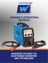
Fig 1 Attaching the Weldarc Shoulder Strap
1
2
3
4
4 Operation
VRD Function
(Voltage Reduction Device)
VRD is optional for the Weldmatic 140i.
The machine is supplied with the
VRD disabled.
VRD Disabled
The open circuit output voltage is
approximately 72 Volts DC.
The ‘VRD SAFE’ indicator on the front
panel will only light up momentarily
during power up.
VRD Enabled
If VRD is required, the VRD can be enabled
by an authorised WIA service agent.
When not welding the ‘VRD SAFE’
indicator on the front panel will come on
and the output voltage will be reduced to
approximately 13.5V, which is below the
required safe level of 35V DC.
Electrode Striking and Restriking
When the electrode is struck on the work
piece the machine will detect a start
condition and increase the output voltage
to start welding. The ‘VRD SAFE’ indicator
will turn off.
To restrike a used electrode it may be
necessary to remove excess flux from
electrode tip.
The strike action is a touch - twist - lift.
THE VRD on the Weldarc 140i complies
with the requirements of AS 1674.2 for
use in ‘Category C’ environments.
Shoulder Strap
To attach the shoulder strap to the
Weldarc, feed the strap through the top of
the shoulder strap bracket located on top
of the Weldarc at the front and rear.

Operators Manual
8
Trusted by the best
WIN564B
(WHEN ENABLED)
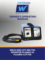
Fig 2 Weldarc 140i Controls
2
1 VRD Safe Mode Indicator
This light is on when the voltage across the
output terminals is reduced to a safe level.
2 Power On Indicator
3 Over Temperature Indicator
This light is on if any internal thermal
protection devices have operated or the
supply voltage is too high or too low.
4 Weld Mode Selection Switch
Use this switch to select between modes.
There are two weld modes available:
4.1 TIG Welding (GTAW): Lift arc start, using
TIG welding torch with separate gas supply.
4.2 Stick Electrode Welding (MMAW).
This mode is used for all MMAW stick
electrode process.
5 Weld Current Control
This control sets the output current level of
the power source within the available range.
Rotate the knob clockwise to increase the
output current.
6 Power On/Off Switch
In the OFF position, this switch isolates the
power source from the mains power supply.
The switch is located on the rear panel.
5 Controls
4.1
6
Power Switch
Located on the rear panel
1
3
4
5
4.2

Weldmatic 140i
Model No MC104, Iss A 09/15 9
6 Installation
Connection to Electrical Mains Power
Supply
The Weldarc 140i is fitted with a 10 Amp
plug and socket.
The minimum capacity of the main power
supply wiring and power outlet supplying a
welder is selected according to the Effective
Primary Current of the equipment. Refer to
Section 3.
The minimum recommended main power
supply circuit breaker ratings for Weldarc
inverters are listed in Section 3.
The current rating of the mains cable
depends on cable size and method of
installation. Refer to AS/NZS 3008.1, Table 9.
If it becomes necessary to replace the mains
flexible supply cable, use only cable with
correct current rating. See Section 3.
If it is necessary to use an extension power
supply cable, ensure that it is rated as per
Section 3. Voltage drop which will occur over
long lengths of cable will reduce the quality
of welds and the maximum welding current
available from the equipment.
As noted previously, it is not recommended
that the Weldarc inverter be powered from
small engine-driven generator sets unless
they have adequate voltage regulation. Poor
regulation results in peaks of supply voltage
which can occur with some equipment
of this type. Excessive voltage peaks can
damage the circuits of the welder.
7 Basic Welding Information
Stick Welding (MMAW)
Connection for Stick Welding
It is important to select the electrode polarity
in accordance with the manufacturers
recommendations for that electrode. Most
common electrodes, including cellulose
types, are operated with the electrode at
positive polarity, as illustrated in Figure 3.
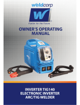
Fig 3 Connections for Stick Welding (MMAW),
Electrode Positive
Stick Welding
Be certain that you are wearing suitable
protective clothing, gloves etc and that you
are working in a non-hazardous area. If
necessary, refer again to Section 1 - Safe
Practices in this manual.
Connect the work clamp to the work piece.
Place the desired electrode in the electrode
holder.
Turn on the power switch located on the rear
panel. Wait approximately 5 seconds as the
unit goes through its initiation sequence.
Use the Weld Mode Selection Switch to
select Stick Mode.
Work clamp
To electrode
holder
(-) output terminal
(+) output terminal

Operators Manual
10
Trusted by the best
Select an appropriate welding current for
the electrode diameter by setting the knob
on the machine front panel. WIA AUSTARC
electrodes will give the best results.
To strike the arc, drag the end of the
electrode along the work piece as if striking
a match. As the arc initiates, lift the electrode
slightly away, aiming to establish an arc
length of approximately 3mm.
As the electrode end is consumed, feed the
electrode into the arc in order to maintain
arc length. As a general rule, the arc should
be held as short as possible while still giving
stable burn off and good weld appearance.
An arc which is too long cause an unwieldy
flow of metal with a rough weld appearance
and reduced penetration. An arc too short
leads to a narrow weld deposit and “stuttery”
arc characteristics, and the electrode is liable
to freeze onto the work piece.
As the solidified weld deposit forms, move
the end of the electrode slowly along
the weld path, aiming to maintain a pool
of molten weld metal behind the arc.
Decreasing this rate of travel will result in a
wider weld deposit, and similarly increasing it
will narrow the weld deposit.
Always fill the crater which tends to form
at the end of a weld deposit, by pausing
momentarily before withdrawing the electrode
to break the arc. Unfilled craters are a point
of weakness, and can lead to weld cracking.
Current Range for General Purpose
Electrodes
Diameter (mm) Current (Amps)
2.0 40 -60
2.5 60 - 85
3.2 90 - 130
TIG Welding (GTAW)
Connection for TIG Welding
For TIG Welding, the torch is connected
negative terminal. Figure 4 illustrates the
correct connection of the welding torch
and gas supply. Welding grade Argon is the
shielding gas most commonly used for DC
GTAW welding.
Before first use of the welding torch,
allow gas to purge the torch and hoses for
5 minutes at approximately 10 litres/min. For
welding purposes, the gas flow rate should
be set in the range 2-5 litres/min.
Tungsten electrodes for DC GTAW should
be 1-2% Thoriated or Witstar. This type will
provide the best arc initiation, arc stability and
tip shape retention characteristics. Thoriated
electrodes can be recognised by a red coded
end. The tungsten electrode is ground to
a point, with the grinding marks pointing
towards the tip. For welding currents less
than 20 amps, the included angle of the point
should be 30
o
, for currents greater than 20
amps, the recommended angle is 60
o
. When
set in the torch, the tungsten should protrude
6mm from the ceramic gas nozzle.
TIG Welding Operation
Connect the Work Clamp to the work piece.
Turn on the power switch located on the rear
panel. Wait approximately 5 seconds as the
unit goes through its initiation sequence.
Use the Weld Mode Selection Switch to
select TIG Mode.
Select an appropriate welding current for the
job by setting the knob on the machine front
panel.
To initiate the arc, lightly touch the tungsten
electrode onto the work piece, then smoothly
lift it away to establish an arc length slightly
longer than the diameter of the electrode.

Weldmatic 140i
Model No MC104, Iss A 09/15 11
Use of a copper striking plate can be used to
avoid electrode contamination. The electrode
can also be contaminated by contact with
the filler rod. A contaminated electrode
produces an unstable arc. if this occurs
regrind the electrode tip.
Fig 4 Cable and Hose Connections for TIG
welding
Before removing the equipment
cover, ENSURE that the equipment
is disconnected from the mains
power supply. When the equipment
is energised LETHAL VOLTAGES are
present on the electrical components
enclosed.
8 General Maintenance
To TIG Torch
Work clamp
(-) output
terminal
(+) output
terminal

Operators Manual
12
Trusted by the best
If the following checks do not identify
the fault condition, the equipment
should be returned to a WIA Service
agent. Phone 1300 300 884 for details
of your nearest service agent.
No Welding Current
Check:
1 Check that mains supply is available
at the Weldarc inverter power source.
At least one of the display panel lights
should be on. If not, test outlet using a
known working appliance.
2 Check that the welding and work leads
are connected securely to the output
sockets at the front of the machine.
3 Check for continuity of the work lead,
work clamp and electrode holder. Loose
connections can prevent proper flow of
the welding current.
4 The Weldarc inverter welding power
source incorporates an in built protection
device which will operate if the unit is
overloaded. In this event, the machine
will not deliver welding current, and the
Over Temp light will be on. Leave the
machine energised with the fan running
to achieve the maximum cooling rate.
5 If the supply voltage is too high or too
low then the Over Temp light will be on
and the machine will not deliver welding
current.
Check the mains voltage supply. Long
extension cords can cause low voltage.
A generator can cause high voltage.
9 External Trouble Shooting
The electrical components of the equipment
are shown in the circuit diagram below. The
Weldarc inverter is an inverter type design,
where the mains supply is first rectified,
filtered then chopped to a high frequency
before being applied to the welding
transformer. The output of this transformer
is rectified to form the welding output of the
machine.
10 Service Information
Before removing the equipment
cover, ENSURE that the equipment
is disconnected from the mains
power supply. When the equipment
is energised LETHAL VOLTAGES are
present on the electrical components
enclosed.
CAUTION: The following
information is intended for use
by qualified service personnel.
When the unit is energised
LETHAL VOLTAGES are present
on the electrical and electronic
components. It is not intended that
persons without suitable training
and knowledge attempt to perform
service tasks on the components of
this welder.

Weldmatic 140i
Model No MC104, Iss A 09/15 13
Fig 11 Weldarc 140i Circuit Diagram
1 2
1 2
SW1
L1
EARTH
AC1
AC2
1
2
3 4
220V~240VA
C
EARTH
AC1
AC2
G
CE
G
CE
6
7
4
5
1
2
EARTH
+
1
-
2
O
3
G
4
2
2
C2
C10
EARTH
3
5
4
12
2
1
3
4
D1
2
1
3 4
D2
2
1
3 4
2
1
3 4
VCC
SGND
G
CE
G
CE
G1
E1
G2 E2
G1
G2
E1
E2
OHT1
GND
+24V
CS1
CS2
V+
V-
-15V
+15V
IFB
MMA
IP-1
O.C
OHT2
VCC
SGND
J1+
OHT
FAN
O.C1
VCC-1
G1 G2E1 E2
1
2
CN2
12
3
FAN
FAN1
+
-
NTC1
SGND
VCC
1
2
3
CN4
1
2
3
CN5
1
2
CN3
AC
1
AC
2
+
3
-
4
+15V
1
2
3
4
5
6
7
8
2CN1
NTC2
1
2
3
4
CN201
SGND
1
2
3
4
5
6
7
8
CN6
IFB
AC
1
AC
2
+
3
-
4
PWA023
PWA022
10.1 Circuit Diagrams – Power Source

Operators Manual
14
Trusted by the best
Fig 12 Weldarc 140i Power Source Assembly
11.1 Assembly and Parts List - Weldarc 140i Power Source
2
1
4
5
6
7
8
12
13
14
15
3
11
9
10

Weldmatic 140i
Model No MC104, Iss A 09/15 15
Item # Part # Description Qty
1 PAN159 Outer Cover 1
2 M0064 Handle 1
3 D0035 IGBT 4
4 PWA022 PCB Main Control 140i 1
5 PWA023 PCB Front Panel 1
6 M0065 Front Panel 1
7 M0058 Knob 1
8 SA140-0/2 Output Socket 2
9 WIN564 Front Panel Sticker 1
10 R0032 Thermistor Output 1
11 D0036 Input Rectifier 2
12 R0031 Thermistor Input 1
13 M0066 Rear Panel 1
14 FAN012 Fan 1
15 E0078 Main Switch 1
16 REG003 Argon Regulator 1
17 SA32-0/1 Dinse Plug 1
18 62513 Blue Oxy Single Gas Hose, 5 mm 1
Not shown MC104-40 Operating Manual 1
16
17
18

Operators Manual
16
Trusted by the best
12 Warranty Information
WIA Weldmatic MIG &
Weldarc MMA Equipment
2 Year Warranty Statement
Welding Industries of Australia (WIA)
warrants to the original retail purchaser
that the Weldmatic welding machine
purchased (Product) will be free from defects
in materials and workmanship for a period
of 2 years from the date of purchase of
the Product by the customer. If a defect in
material or workmanship becomes evident
during that period, Welding Industries of
Australia will, at its option, either:
• Repair the Product (or pay for the costs
of repair of the Product); or
• Replace the Product.
In the event of such a defect, the customer
should return the Product to the original
place of purchase, with proof of purchase,
or contact Welding Industries of Australia on
1300 300 884 to locate an authorised service
agent.
Any handling and transportation costs
(and other expenses) incurred in claiming
under this warranty are not covered by this
warranty and will not be borne by Welding
Industries of Australia. Welding Industries of
Australia will return the replacement product,
if original found to be faulty, freight free to
the customer.
This warranty covers the Weldarc power
source only, and does not extend to the
accessories included in the original purchase
package.
The obligation of Welding Industries of
Australia under this warranty is limited to the
circumstances set out above and is subject to:
• The customer being able to provide
proof of purchase of the Product and the
purchase price paid for the Product;
• The relevant defect in materials or
workmanship;
• The Product not having been altered,
tampered with or otherwise dealt with
by any person in a manner other than
as intended in respect of the relevant
Product; and
• The Product not having been used or
applied in a manner that is contrary to
customary usage or application for the
relevant Product or contrary to any stated
instructions or specification of Welding
Industries of Australia.

Weldmatic 140i
Model No MC104, Iss A 09/15 17
Our goods come with guarantees that
cannot be excluded under the Australian
Consumer Law. You are entitled to a
replacement or refund for a major failure and
for compensation for any other reasonably
foreseeable loss or damage. You are also
entitled to have the goods repaired or
replaced if the goods fail to be of acceptable
quality and the failure does not amount to
a major failure. The benefits given by this
warranty are in addition to other rights and
remedies which may be available to the
customer under any law in relation to goods
and services to which this warranty relates.
Warranty provided by:
Welding Industries of Australia
(ABN 63 004 235 063)
A Division of ITW Australia Pty Ltd
5 Allan Street, Melrose Park,
South Australia, 5039
Ph: 1300 300 884
Email: [email protected]
Web: www.welding.com.au

• Lens and helmet comply with
Australian Standards AS/NZS
1338.1 (Auto-Darkening) and AS/
NZS 1337.1B (High Impact)
• Convenient external shade control
• Magnifying lens holder
WIA Blue Helmet
Part No: 235620
DESIGNED FOR THE WELDER
WHO WANTS PROTECTION,
PERFORMANCE & COMFORT
AT AN AFFORDABLE PRICE.
• 1 year warranty
(Auto-Darkening lens only)
• Battery powered with solar-assist
• Variable shade control
• Grind Mode.
For more information call 1300 300 884 or visit welding.com.au
/