Page is loading ...

User Manual
ULTRA HEX BAR 12
Revised 09/29/2022

2
©2022 ADJ Products, LLC all rights reserved. Information, specications, diagrams, images, and
instructions herein are subject to change without notice. ADJ Products, LLC logo and identifying prod-
uct names and numbers herein are trademarks of ADJ Products, LLC. Copyright protection claimed
includes all forms and matters of copyrightable materials and information now allowed by statutory or
judicial law or hereinafter granted. Product names used in this document may be trademarks or regis-
tered trademarks of their respective companies and are hereby acknowledged. All non-ADJ Products,
LLC brands and product names are trademarks or registered trademarks of their respective compa-
nies.
ADJ Products, LLC and all afliated companies hereby disclaim any and all liabilities for property,
equipment, building, and electrical damages, injuries to any persons, and direct or indirect economic
loss associated with the use or reliance of any information contained within this document, and/or as
a result of the improper, unsafe, insufcient and negligent assembly, installation, rigging, and opera-
tion of this product.
Europe Energy Saving Notice
Energy Saving Matters (EuP 2009/125/EC)
Saving electric energy is a key to help protecting the enviroment. Please turn off all electrical products when
they are not in use. To avoid power consumption in idle mode, disconnect all electrical equipment from power
when not in use. Thank you!
DOCUMENT VERSION
Due to additional product features and/or enhancements, an updated version of
this document may be available online.
Please check www.adj.com for the latest revision/update of this manual
before beginning installation and/or programming.

3
TABLE OF CONTENTS
Introduction 4
Limited Warranty (USA Only) 5
Warranty Registration | Features 6
Installation 7
Safety Precautions 8
Setup 9
Control Panel 11
Operating Instructions 12
Primary-Secondary Configuration 16
ADJ RFC Operation 17
DMX Traits 18
Color Macros Chart 21
Photometric Chart | Dimmer Curve Chart 22
Power Cord Daisy Chain | Cleaning | Fuse Replacement 23
Trouble Shooting 24
Specifications 25

4
Unpacking: Thank you for purchasing the Ultra Hex Bar 12 by ADJ Products, LLC. Every device has
been thoroughly tested and has been shipped in perfect operating condition. Carefully check the ship-
ping carton for damage that may have occurred during shipping. If the carton appears to have been
damaged, carefully inspect your xture for any damage and be sure all accessories necessary to oper-
ate the unit have arrived intact. In the event that damage has been found or parts are missing, please
contact our toll free customer support number for further instructions. Do not return this unit to your
dealer without rst contacting customer support.
Introduction: The Ultra Hex Bar 12 is a DMX intelligent, LED bar xture, and can be used in a stand
alone mode or connected in a primary/secondary conguration. This par has six operating modes:
Sound Active mode, Auto mode, Program mode, RGBWA + UV dimmer mode, Static Color mode, and
DMX control mode.
Customer Support: Contact ADJ Service for any product related service and support needs. Also visit
forums.adj.com with questions, comments or suggestions.
Parts: To purchase parts online visit:
http://parts.adj.com (US)
http://www.adjparts.eu (EU)
ADJ SERVICE USA - Monday - Friday 8:00am to 4:30pm PST
Voice: 800-322-6337 | Fax: 323-582-2941 | [email protected]
ADJ SERVICE EUROPE - Monday - Friday 08:30 to 17:00 CET
Voice: +31 45 546 85 60 | Fax: +31 45 546 85 96 | [email protected]
ADJ PRODUCTS LLC USA
6122 S. Eastern Ave. Los Angeles, CA. 90040
323-582-2650 | Fax 323-532-2941 | www.adj.com | info@adj.com
ADJ SUPPLY Europe B.V
Junostraat 2 6468 EW Kerkrade, The Netherlands
+31 (0)45 546 85 00 | Fax +31 45 546 85 99
www.americandj.eu | [email protected]
ADJ PRODUCTS GROUP Mexico
AV Santa Ana 30 Parque Industrial Lerma, Lerma, Mexico 52000
+52 (728) 282-7070
CAUTION! To avoid the risk of shock or re, do NOT expose this unit to rain or moisture! This unit is
intended only for dry, indoor environments!
CAUTION! There are no user serviceable parts inside this unit. Do not attempt any repairs yourself,
as doing so will void your manufacturer’s warranty. In the unlikely event your unit may require service,
please contact ADJ Products, LLC.
Do not discard the shipping cartoon in the trash. Please recycle when ever possible.
INTRODUCTION

5
LIMITED WARRANTY (USA ONLY)
A. ADJ Products, LLC hereby warrants, to the original purchaser, ADJ Products, LLC products to be free of
manufacturing defects in material and workmanship for a prescribed period from the date of purchase (see
specic warranty period on reverse). This warranty shall be valid only if the product is purchased within the
United States of America, including possessions and territories. It is the owner’s responsibility to establish
the date and place of purchase by acceptable evidence, at the time service is sought.
B. For warranty service, you must obtain a Return Authorization number (RA#) before sending the product
back—please contact ADJ Products, LLC Service Department at 800-322-6337. Send the product only to
the ADJ Products, LLC factory. All shipping charges must be prepaid. If the requested repairs or service
(including parts replacement) are within the terms of this warranty, ADJ Products, LLC will pay return ship-
ping charges only to a designated point within the United States. If the entire instrument is sent, it must be
shipped in its original package and packaging material. No accessories should be shipped with the product.
If any accessories are shipped with the product, ADJ Products, LLC shall incur no liability whatsoever for
loss of or damage to any such accessories, nor for the safe return thereof.
C. This warranty is void if the product serial number and/or labels are altered or removed; if the product is
modied in any manner which ADJ Products, LLC concludes, after inspection, affects the reliability of the
product; if the product has been repaired or serviced by anyone other than the ADJ Products, LLC factory
unless prior written authorization was issued to purchaser by ADJ Products, LLC; if the product is dam-
aged because it was not properly maintained as set forth in the product instructions, guidelines and/or user
manual.
D. This is not a service contract, and this warranty does not include maintenance, cleaning, or periodic check-
up. During the period specied above, ADJ Products, LLC will replace defective parts at its expense with
new or refurbished parts, and will absorb all expenses for warranty service and repair labor by reason of
defects in material or workmanship. The sole responsibility of ADJ Products, LLC under this warranty shall
be limited to the repair of the product, or replacement thereof, including parts, at the sole discretion of ADJ
Products, LLC. All products covered by this warranty were manufactured after August 15, 2012, and bear
identifying marks to that effect.
E. ADJ Products, LLC reserves the right to make changes in design and/or improvements upon its products
without any obligation to include these changes in any products theretofore manufactured.
F. No warranty, whether expressed or implied, is given or made with respect to any accessory supplied with
products described above. Except to the extent prohibited by applicable law, all implied warranties made by
ADJ Products, LLC in connection with this product, including warranties of merchantability or tness, are
limited in duration to the warranty period set forth above. And all warranties, whether expressed or implied,
including warranties of merchantability or tness, are limited in duration to the warranty period set forth
above. The consumer’s and/or dealer’s sole remedy shall be such repair or replacement as is expressly
provided above; and under no circumstances shall ADJ Product, LLC be liable for any loss and/or damage,
direct and/or consequential arising out of the use of, and/or inability to use this product.
G. This warranty is the only written warranty applicable to ADJ Products, LLC products, and supersedes all
prior warranties and written descriptions of warranty terms and conditions heretofore published.
MANUFACTURER’S LIMITED WARRANTY PERIODS:
• Non-LED Lighting Products = 1-Year (365 Days) (Including Special Effect Lighting, Intelligent Lighting,
UV lighting, Strobes, Fog Machines, Bubble Machines, Mirror Balls, Par Cans, Trussing, Lighting Stands,
Power/Data Distribution, etc. excluding LED and lamps)
• Laser Products = 1-Year (365 Days) (excluding laser diodes which have a 6-Month Limited Warranty)
• LED Products = 2-Year (730 Days) (excluding batteries which have a 180 Day Limited Warranty)
• NOTE: 2-Year (730 Days) Limited Warranty ONLY applies to product purchased within the United States.
StarTec Series = 1-Year (365 Days) (excluding batteries which have a 180 Day Limited Warranty)
• ADJ DMX Controllers = 2 Year (730 Days)
• American Audio Products = 1 Year (365 Days)

6
FEATURES
• Multi-Colors
• Six Operating Modes
• Electronic Dimming 0-100%
• Built in Microphone
• DMX-512 protocol
• 3-Pin DMX Connection
• 5 DMX Modes: 6, 7, 8, 12, & 36 Channel Mode.
• ADJ RFC compatiable (Sold Separately)
• Power Cord Daisy Chain (see Power Cord Daisy Chain section of this manual)
WARRANTY REGISTRATION
This device carries a 2-year limited warranty. Please fill out the enclosed warranty card to validate
your purchase. All returned service items, whether under warranty or not, must be freight pre-paid and
accompanied by a return authorization (R.A.) number. The R.A. number must be clearly written on the
outside of the return package. A brief description of the problem as well as the R.A. number must also
be written down on a piece of paper included in the shipping carton. If the unit is under warranty, you
must provide a copy of your proof of purchase invoice. You may obtain an R.A. number by contacting
our customer support team. All packages returned to the service department not displaying an R.A.
number on the outside of the package will be returned to the shipper.

7
INSTALLATION
CLAMP INSTALLATION
This fixture features a mounting clamp attachment points at the base of each foot, as well as two
safety cable attachment points located on the back of the fixture (see the illustration below). When
mounting the fixture to a truss or any other suspended or overhead installation, be sure to secure
appropriately rated clamps (not included) to the clamp attachment points and attach a separate
SAFETY CABLE of the appropriate safety rating to each safety cable rigging point. Please note
that this device requires the use of TWO mounting clamps and TWO independently-secured
safety cables for secure, stable installation!
SAFETY CABLE
ALWAYS ATTACH A SAFETY CABLE WHENEVER INSTALLING THIS FIXTURE IN A
SUSPENDED ENVIRONMENT TO ENSURE THAT THE FIXTURE WILL NOT FALL IF
THE CLAMP FAILS.
RIGGING
Overhead rigging requires extensive experience, including but not limited to: calculating working
load limits, understanding the installation material being used, and periodic safety inspection of all
installation material and the fixture itself. If you lack these qualifications, do not attempt to perform
the installation yourself. Improper installation can result in bodily injury.
MOUNTING
CLAMP
ATTACHMENT
POINT
MOUNTING
CLAMP
ATTACHMENT
POINT
SAFETY
CABLE
LOOPS

8
SAFETY PRECAUTIONS
• To reduce the risk of electrical shock or fire, do not expose this unit to rain or moisture.
• Do not spill water or other liquids into or on to your unit.
• Do not attempt to operate this unit if the power cord is frayed or broken.
• Do not attempt to remove or break off the ground prong from the electrical cord. This prong is
used to reduce the risk of electrical shock and fire in event of an internal short.
• Disconnect from main power before making any type of connection.
• Do not remove the cover under any conditions. There are no user serviceable parts inside.
• Never operate this unit with its cover removed.
• Never plug this unit in to a dimmer pack.
• Always be sure to mount this unit in an area that will allow proper ventilation. Allow about 6”
(15cm) between this device and a wall.
• Do not attempt to operate this unit if it has been damaged in any way.
• This unit is intended for indoor use only, and use of this product outdoors voids all warranties.
• During long periods of non-use, disconnect the unit’s main power.
• Always mount this unit in safe and stable matter.
• Power-supply cords should be routed so that they are not likely to be walked on or pinched by
items placed upon or against them, paying particular attention to the point at which they exit from
the unit.
• Cleaning - The fixture should be cleaned only as recommended by the manufacturer. See the
Cleaning section of this manual for details.
• Heat - The appliance should be situated away from heat sources such as radiators, heat registers,
stoves, or other appliances (including amplifiers) that produce heat.
• The fixture should be serviced by qualified service personnel when:
A. The power-supply cord or the plug have been damaged.
B. Objects have fallen onto, or liquid has been spilled into, the fixture.
C. The fixture does not appear to operate normally or exhibits a marked change in performance.
D. The fixture has fallen and/or has been subjected to extreme handling.

9
SETUP
Power Supply: The ADJ Ultra Hex Bar 12 contains an automatic voltage switch, which will auto mati-
cally sense the voltage when it is plugged into the power source. With this switch there is no need to
worry about the correct power voltage, and this unit can be plugged in anywhere.
DMX-512: DMX is short for Digital Multiplex. This is a universal protocol used as a form of communi-
cation between intelligent xtures and controllers. A DMX controller sends DMX data instructions from
the controller to the xture. DMX data is sent as serial data that travels from xture to xture via the
DATA “IN” and DATA “OUT” XLR terminals located on all DMX xtures (most controllers only have a
DATA “OUT” terminal).
DMX Linking: DMX is a language allowing all makes and models of different manufacturers to be
linked together and operate from a single controller, as long as all xtures and the controller are
DMX compliant. To ensure proper DMX data transmission, try to use the shortest cable path possible
when linking several DMX xtures. The order in which xtures are connected in a DMX line does not
inuence the DMX addressing. For example, a xture assigned a DMX address of 1 may be placed
anywhere in a DMX line: at the beginning, at the end, or anywhere in the middle. When a xture is
assigned a DMX address of 1, the DMX controller knows to send DATA assigned to address 1 to that
unit, no matter where it is located in the DMX chain.
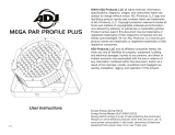
Data Cable (DMX Cable) Requirements (For DMX Operation): The Ultra Hex Bar 12 can be con-
trolled via DMX protocol. The Ultra Hex Bar 12 has 5 DMX channel modes, and detailed information
can be found in the DMX Traits section of this manual. Your unit and your DMX controller require a
standard 3-pin XLR connector for data input and data output (Figure 1). We recommend Accu-Cable
DMX cables. If you are making your own cables, be sure to use standard 110-120 Ohm shielded
cable (This cable may be purchased at almost all pro lighting stores). Your cables should be made
with a male XLR connector at one end, and a female XLR connector at the other. Also remember that
DMX cable must be daisy chained and cannot be split.
Figure 1

10
SETUP
Notice: Be sure to follow figures two and three when making your own cables. Do not use the ground
lug on the XLR connector. Do not connect the cable’s shield conductor to the ground lug or allow the
shield conductor to come into contact with the XLR’s outer casing. Grounding the shield could cause a
short circuit and erratic behavior.
Special Note: Line Termination. When longer runs of cable are used, you may need to use a termi-
nator on the last unit to avoid erratic behavior. A terminator is a 110-120 ohm 1/4 watt resistor which is
connected between pins 2 and 3 of a male XLR connector (DATA+ and DATA-). This unit is inserted in
the female XLR connector of the last unit in your daisy chain to terminate the line. Using a cable termi-
nator (ADJ part number Z-DMX/T) will decrease the possibilites of erratic behavior.
5-Pin XLR DMX Connectors. Some manufacturers use 5-pin DMX-512 data cables for DATA trans-
mission in place of 3-pin. 5-pin DMX fixtures may be implemented in a 3-pin DMX line by using a
cable adaptor, which can be purchased at most electronics stores. The chart below details a proper
cable conversion.
Conductor 5-Pin XLR Male (In)3-Pin XLR Female (Out)
Pin 1
Do Not Use
Do Not Use
Pin 3
Pin 2
Pin 1
Pin 3
Pin 2
Not Used
Not Used
Data True (+ signal)
Data Compliment (- signal)
Ground/Shield
3-Pin XLR to 5-Pin XLR Conversion
DMX512 IN
3-PIN XLR
1
2
3
1
2
3
DMX +
DMX -
COMMON
DMX512 OUT
3-PIN XLR
Figure 3
1 Ground 1 Ground
XLR Male Socket
3 Hot
2 Cold 2 Cold
3 Hot
XLR Female Socket
Pin 3 = Data True (positive)
Pin 2 = Data Compliment (negative)
Pin 1 = Ground
1
2
3
Termination reduces signal errors and
avoids signal transmission problems
and interference. It is always advisable
to connect a DMX terminal, (Resistance
120 Ohm 1/4 W) between PIN 2 (DMX-)
and PIN 3 (DMX +) of the last fixture.Figure 4

11
CONTROL PANEL
This fixture includes an easy to navigate control panel display, from which all necessary settings and
adjustments can be made. During normal operation, pressing the MODE button will cycle through
the different functions in the main system menu. Press the SETUP button to select the option dis-
played on the screen, and use the UP and DOWN buttons to adjust the settings for the selected
option. Press the SETUP button once more to confirm the setting. Press the MODE button at any
time to return to the main menu without making any adjustments.
MODE
SET UP
UP
DOWN

12
OPERATING INSTRUCTIONS
Menu Lock:
You can set the menu to lock after 30 seconds. To unlock, press and hold the MODE button for at
least 5 seconds. To set the menu to lock after 30 seconds, press the MODE button until “OTHER” is
displayed. Press the SETUP button so that “LOCK:XXX” is displayed. “XXX” represents either ON or
OFF. Press the UP or DOWN buttons so that ON is displayed. Now the menu will lock after 30s.
LED Display On/Off:
To set the LED display light to turn off after 30 seconds, press the MODE button until “OTHER” is
displayed. Press the SET UP button so that “BLGT:XXX” is displayed. “XXX” represents either ON or
OFF. Press the UP or DOWN buttons so that OFF is displayed. Now the display light will turn off after
30s. Press any button to turn the display on again.
Operating Modes:
The Ultra Hex Bar 12 has six operating modes:
• DMX control mode - This function will allow you to control each individual trait with a standard
DMX 512 controller.
• RGBWA + UV Mode - Choose one of the six colors to remain static, or adjust the intensity of each
color to create a custom color.
• Sound Active mode - The unit will react to sound, chasing through the built in programs.
• Program Mode - The unit will run 1 of 20 built-in programs.
• Auto Mode - The unit will run an auto program.
• Static Color Mode - There are 63 colors to choose from.
DMX Mode:
Operating through a DMX controller gives the user the freedom to create their own programs tai-
lored to their own individual needs. This function also allows you to use your fixtures as spot lights.
The Ultra Hex Bar 12 has 5 DMX modes: 6 Channel mode, 7 Channel mode, 8 Channel mode, 12
Channel mode, and 36 Channel mode. Refer to the DMX Traits section of this manual for detailed
information. This function will allow you to control each individual fixture’s traits with a standard DMX
512 controller.
1. To run your fixture in DMX mode press the MODE button until “DMX MODE: is displayed. Press
the SET UP button so that ADDR:XXX” is displayed. “XXX” represents the current displayed
address.
2. Use the UP or DOWN buttons to select your desired DMX address, then press the SETUP button
to select your DMX Channel mode.
3. Use the UP or DOWN buttons to scroll through the DMX Channel modes until the desired mode
is displayed. The available channel modes are 6-channel, 7-channel, 8-channel, 12-channel, and
36-channel. After you have chosen your desired DMX Channel mode plug in the fixture via the
XLR connections to any standard DMX controller.

13
OPERATING INSTRUCTIONS
RGBWA & UV Dimmer Mode:
1. Plug the fixture in and press the MODE button until “MANUAL” is displayed.
2. When “RED: XXX” is displayed you are in Red dimming mode. Press the UP and DOWN buttons
to adjust intensity. After you have finished adjusting the intensity, or if you would like to skip to the
next color, press the SET UP button.
3. When “GREN: XXX” is displayed you are in Green dimming mode. Press the UP and DOWN but-
tons to adjust intensity.
4. When “BLUE: XXX” is displayed you are in Blue dimming mode. Press the UP and DOWN buttons
to adjust intensity.
5. When “WHIT: XXX” is displayed you are in White dimming mode. Press the UP and DOWN but-
tons to adjust intensity.
6. When “AMBE: XXX” (Amber) is displayed you are in Amber dimming mode. Press the UP and
DOWN buttons to adjust intensity.
7. When “UV: XXX” is displayed you are in UV dimming mode. Press the UP and DOWN buttons to
adjust intensity.
8. After you have adjusted the colors to make your desired color you can then activate strobing by
pressing the SET UP button to enter the strobe mode.
9. “STRO: XX” will be displayed, this is strobe mode. The strobe can be adjusted between “00” (flash
off) to “15” (fastest flash).
Static Color Mode:
1. Plug the fixture in and press the MODE button until “CLR MACS” is displayed. Press the SET UP
button so that “COLOR:XX” is displayed. “XX” represents the current displayed macro.
2. There are 63 colors to choose from. Use the UP and DOWN buttons to scroll through the 63 col-
ors. After you have found your desired color, you can activate strobing by pressing the SET UP
button to enter the strobe mode.
3. “STATIC STRO:XX” will be displayed, indicating that the unit is now in strobe mode. The strobing
can be adjusted between “00” (flash off) to “15” (fastest flash).
Program Mode:
1. Plug the fixture in and press the MODE button until “PROG RUN PROG:XX” is displayed. “XX”
represents the current program that is running.
2. Use the UP or DOWN buttons to scroll through the 20 programs. Once you have found your
desired program, press the SET UP button to adjust the program speed.
3. “SPEED:XX” will be displayed. Use the UP or DOWN button to adjust the speed between “01”
(slowest) and “16” (fastest). Once you have set your desired running speed, press the SET UP
button to enter the fade adjustment mode.
4. “FADE: XX” will be displayed. Use the UP or DOWN button to adjust the speed between “01” (fast-
est) and “16” (slowest) or “00” (Off).
5. After you have adjusted the fade speed you can then activate strobing by pressing the SET UP
button to enter the strobe mode.
6. “STRO: XX” will be displayed, indicating that the device is in strobe mode. The strobe can be
adjusted between “00” (flash off) to “15” (fastest flash).

14
OPERATING INSTRUCTIONS
Auto Run Mode:
1. Plug the xture in and press the MODE button until “AUTO RUN SPEED:XX” is displayed. “XX”
represents the current auto run speed.
2. Use the UP or DOWN button to adjust the speed between “01” (slowest) and “16” (fastest). Once
you have set your desired running speed, press the SET UP button to adjust the fade speed.
3. “FADE: XX” will be displayed. Use the UP or DOWN button to adjust the speed between “01” (fast-
est) and “16” (slowest) or “00” (Off).
4. Activate strobing by pressing the SET UP button to enter the strobe mode.
5. “STRO: XX” will be displayed, indicating that the device is in strobe mode. The strobe can be ad-
justed between “00” (ash off) to “15” (fastest ash).
Sound Active Mode:
In this mode the Ultra Hex Bar 12 will react to sound, and chase through the different colors.
1. Plug the xture in and press the MODE button until “SOUND PRO: XX” is displayed. “XX” is the
current sound sensitivity setting.
2. Use the UP or DOWN buttons to adjust the sound sensitivity. “00” is off, “01 is the least sensitive,
and “16” is the most sensitive.
3. Activate strobing by pressing the SET UP button to enter the strobe mode.
4. “STRO: XX” will be displayed, indicating that the device is in strobe mode. The strobe can be ad-
justed betwenn “00” (ash off) to “15” (fastest ash).
ADJ RFC:
This function is used to activate and deactivate the ADJ RFC control. When this function is activated
you can control the xture using the ADJ RFC (Sold Separately). Please see the ADJ RFC Opera-
tion section of this manual for ADJ RFC controls and functions.
1. Plug the xture in and press the MODE button until “OTHER” is displayed.
2. Press the SET UP button until “RF: XX” is displayed. “XX” represents either “ON” or “OFF”.
3. Use the UP or DOWN buttons to either activate the remote function (On) or deactivate it (Off).
DMX State:
This mode determines how the unit will behave when DMX signal is lost or interrupted. You can also
set this as the operating mode you would like the unit to return to when power is applied.
1. Press the MODE button until “DMX MODE” is displayed.
2. Press the SET UP button so that “NO:XXXX” is displayed. “XXXX” represents the current DMX
state that is displayed.
3. “NO: BLACK” (Blackout) - If the DMX signal is lost or interrupted, the unit will automatically go into
stand by mode.
4. “NO: HOLD” (Last State) - If the DMX signal is lost or interrupted, the xture will stay in the last
DMX set up. If power is applied and this mode is set, the unit will automatically go into the last
DMX set up.
5. “NO: AUTO” (Auto Run) - If the DMX signal is lost or interrupted, the unit will automatically go into
Auto Run mode.
6. Use the UP and DOWN buttons to nd your desired DMX state and press SETUP to conrm and
exit.

15
OPERATING INSTRUCTIONS
Dimmer Curve:
This is used to set the dimming curve used with DMX mode. See page 21 for the different dimming
curves.
1. Plug the xture in and press the MODE button until “DMX MODE” is displayed.
2. Press the SET UP button until “DELAY: X” is displayed. “X” represents the displayed dimmer curve
(0-4).
• 0 - Standard
• 1 - Stage
• 2 - TV
• 3 - Architectural
• 4 - Theatre
3. Press the UP or DOWN button to scroll through and select your desired dimming curve.

16
PRIMARY-SECONDARY CONFIGURATION
This function will allows you to link units together to run in a primary-secondary mode, in which one
unit will act as the controlling unit and the others will react to the controlling unit’s built-in programs.
Any unit can act as a primary or as a secondary, but only one unit can be programmed to act as the
primary in a given system.
Primary-Secondary Connections and Settings:
Daisy chain your units via the XLR connector on the rear of each unit. Use standard XLR data cables
to link your units together. Remember that the male XLR connector is the input and the female XLR
connector is the ouput. The rst unit in the chain (primary) will use the female XLR connector only,
while the last unit in the chain will use the male XLR connector only.
Set the primary unit to your desired mode of operation.
Connect the rst secondary unit to the primary.
Set the secondary unit to the “DMX MODE ADDR” setting. Repeat with each secondary unit in the
system. The secondary unit(s) will now follow the primary.

17
ADJ RFC OPERATION
The ADJ RFC remote (sold seperately) has many different functions and allows you to control your
Ultra Hex Bar 12 from a distance. Maximum range is 150 ft. To use the RFC, you must rst activate
the xtures receiver, as described in the Operating Instructions section of this manual.
BLACKOUT - Pressing this button will blackout the xture. Press and hold this button for at least 3
seconds to activate default mode. All modes will return to their default settings.
AUTO RUN - This button will activate the Auto Run mode.
• You can control the fade speed by pressing the FLASH button twice and then adjust the fade
speed using the “+” and “-” buttons.
• Adjust the program speed of the Auto Run by pressing the SPEED button and then adjust the
speed using the “+” and “-” buttons.
• Press the FLASH button once to activate strobe and adjust the strobe speed using the “+” and “-”
buttons.
PROGRAM SELECTION - This button will activate 1 of 2 modes: Static Color mode or Program
mode.
• Press this button to activate Static Color mode. Use the “+” and “-” buttons to scroll through the
63 colors. Once you have found your desired color, you can press the FLASH button to activate
strobing. Use the “+” and “-” buttons adjust the strobe speed.
• Press this button to activate Program mode. Use the “+” and “-” buttons to scroll through the 20
different programs. Once you have found your desired program, you can press the SPEED button
and use the “+” and “-” buttons to adjust the program speed. Adjust the fade speed by pressing the
FLASH button twice and use the “+” and “-” buttons to adjust the fade speed. Press the FLASH
button once to activate strobe and adjust the strobe speed using the “+” and “-” buttons.
FLASH - This button will activate the ash (strobe) effect. You can control the ash speed by pressing
the “+” and “-” buttons. In Auto mode and Program mode, press this button twice to enter fade speed
adjustment. Use the “+” and “-” buttons to adjust the fade speed.
SPEED - Press this button and use the “+” & “-” buttons to adjust the speed of the Built-In Programs.
SOUND ACTIVE - This button activates sound active mode. Use the “+” & “-” buttons to adjust the
sound sensitivity level.
R G B W/A - Press any one of these buttons and the press the “+” or “-” to adjust the brightness.
Press the Flash button to activate strobing and use the “+” or “-” buttons to adjust the strobe speed.
NOTE: Press the W/A button to scroll through White, Amber, and UV.
“+” and “-” - Use these buttons to adjust the ash rate, speed of the Auto Run and built-in programs,
fade speed, sound sensitivity, and output intensity. These buttons are also used to scroll through the
static colors and built-in programs.

18
DMX TRAITS
CHANNEL DMX
VALUES FUNCTION
6CH 7CH 8CH 12CH 36CH
1 1 1 1 000 - 255 Red, 0% to 100%
2 2 2 2 000 - 255 Green, 0% to 100%
3 3 3 3 000 - 255 Blue, 0% to 100%
4 4 4 4 000 - 255 White, 0% to 100%
5 5 5 5 000 - 255 Amber, 0% to 100%
6 6 6 6 000 - 255 UV, 0% to 100%
7 000 - 255 Color Macros, see Color Macro Chart section of this manual
7 8
Strobing
000 - 031 Off
032 - 063 LED On
064 - 095 Strobing, slow to fast
096 - 127 LED On
128 - 159 Strobe Pulse, slow to fast
160 - 191 LED On
192 - 223 Random Strobing
224 - 255 LED On
7 8 9 000 - 255 Master Dimmer, 0% to 100%
10
Programs
000 Off
001 - 024 Program 1
025 - 035 Program 2
036 - 046 Program 3
047 - 057 Program 4
058 - 068 Program 5
069 - 079 Program 6
080 - 090 Program 7
091 - 101 Program 8
102 - 112 Program 9
113 - 123 Program 10
124 - 134 Program 11
135 - 145 Program 12
146 - 156 Program 13
157 - 167 Program 14
168 - 178 Program 15
179 - 189 Program 16
190 - 200 Program 17
201 - 211 Program 18
212 - 222 Program 19
223 - 233 Program 20
234 - 255 Sound Active Programs
CONTINUED ON NEXT PAGE

19
DMX TRAITS
CHANNEL DMX
VALUES FUNCTION
6CH 7CH 8CH 12CH 36CH
11
Program Speed / Sound Sensitivity
000 - 255
Program Speed, slow to fast
- OR -
Sound Sensitivity, least to most sensitive
12
Dimmer Mode
000 - 020 Standard
021 - 040 Stage
041 - 060 TV
061 - 080 Architectural
081 - 100 Theatre
101 - 255 Default dimmer setting
1 000 - 255 Red, Pixel 1 & 2, 0% to 100%
2 000 - 255 Green, Pixel 1 & 2, 0% to 100%
3 000 - 255 Blue, Pixel 1 & 2, 0% to 100%
4 000 - 255 White, Pixel 1 & 2, 0% to 100%
5 000 - 255 Amber, Pixel 1 & 2, 0% to 100%
6 000 - 255 UV, Pixel 1 & 2, 0% to 100%
7 000 - 255 Red, Pixel 3 & 4, 0% to 100%
8 000 - 255 Green, Pixel 3 & 4, 0% to 100%
9 000 - 255 Blue, Pixel 3 & 4, 0% to 100%
10 000 - 255 White, Pixel 3 & 4, 0% to 100%
11 000 - 255 Amber, Pixel 3 & 4, 0% to 100%
12 000 - 255 UV, Pixel 3 & 4, 0% to 100%
13 000 - 255 Red, Pixel 5 & 6, 0% to 100%
14 000 - 255 Green, Pixel 5 & 6, 0% to 100%
15 000 - 255 Blue, Pixel 5 & 6, 0% to 100%
16 000 - 255 White, Pixel 5 & 6, 0% to 100%
17 000 - 255 Amber, Pixel 5 & 6, 0% to 100%
18 000 - 255 UV, Pixel 5 & 6, 0% to 100%
19 000 - 255 Red, Pixel 7 & 8, 0% to 100%
20 000 - 255 Green, Pixel 7 & 8, 0% to 100%
21 000 - 255 Blue, Pixel 7 & 8, 0% to 100%
22 000 - 255 White, Pixel 7 & 8, 0% to 100%
23 000 - 255 Amber, Pixel 7 & 8, 0% to 100%
24 000 - 255 UV, Pixel 7 & 8, 0% to 100%
25 000 - 255 Red, Pixel 9 & 10, 0% to 100%
26 000 - 255 Green, Pixel 9 & 10, 0% to 100%
27 000 - 255 Blue, Pixel 9 & 10, 0% to 100%
28 000 - 255 White, Pixel 9 & 10, 0% to 100%
29 000 - 255 Amber, Pixel 9 & 10, 0% to 100%
30 000 - 255 UV, Pixel 9 & 10, 0% to 100%
CONTINUED ON NEXT PAGE

20
DMX TRAITS
CHANNEL DMX
VALUES FUNCTION
6CH 7CH 8CH 12CH 36CH
31 000 - 255 Red, Pixel 11 & 12, 0% to 100%
32 000 - 255 Green, Pixel 11 & 12, 0% to 100%
33 000 - 255 Blue, Pixel 11 & 12, 0% to 100%
34 000 - 255 White, Pixel 11 & 12, 0% to 100%
35 000 - 255 Amber, Pixel 11 & 12, 0% to 100%
36 000 - 255 UV, Pixel 11 & 12, 0% to 100%
NOTES:
In 12-channel mode:
• When Channel 7 is being used, Channels 1-6 will not work.
• When Channel 10 is between the values of 1-233, Channel 11 will control the program speed.
• When Channel 10 is between the values of 234-255, Channel 11 will control the sound sensitivity.
/