Selcom ST 402 Cayman Operating instructions
- Type
- Operating instructions
This manual is also suitable for
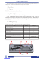
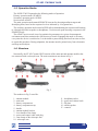
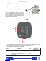
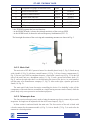
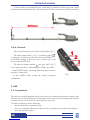
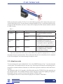
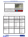
Selcom ST 402 Cayman is an advanced nonlinear junction detector that allows you to detect and locate a wide range of electronic devices, including eavesdropping technology, mobile phones, and other devices utilizing semiconductor technology. It operates in two primary modes: SEARCH and AUDIO. In SEARCH mode, the device visually indicates the presence and relative strength of detected signals, while in AUDIO mode, you can listen to the demodulated response through headphones or the built-in speaker.
Selcom ST 402 Cayman is an advanced nonlinear junction detector that allows you to detect and locate a wide range of electronic devices, including eavesdropping technology, mobile phones, and other devices utilizing semiconductor technology. It operates in two primary modes: SEARCH and AUDIO. In SEARCH mode, the device visually indicates the presence and relative strength of detected signals, while in AUDIO mode, you can listen to the demodulated response through headphones or the built-in speaker.


-
 1
1
-
 2
2
-
 3
3
-
 4
4
-
 5
5
-
 6
6
-
 7
7
-
 8
8
-
 9
9
-
 10
10
-
 11
11
-
 12
12
-
 13
13
-
 14
14
-
 15
15
-
 16
16


Selcom ST 402 Cayman Operating instructions
- Type
- Operating instructions
- This manual is also suitable for
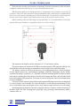
Selcom ST 402 Cayman is an advanced nonlinear junction detector that allows you to detect and locate a wide range of electronic devices, including eavesdropping technology, mobile phones, and other devices utilizing semiconductor technology. It operates in two primary modes: SEARCH and AUDIO. In SEARCH mode, the device visually indicates the presence and relative strength of detected signals, while in AUDIO mode, you can listen to the demodulated response through headphones or the built-in speaker.
Ask a question and I''ll find the answer in the document
Finding information in a document is now easier with AI
Other documents
-
REI ORION™ NJE-4000 Owner's manual
-
-
-
Netopia Cayman 3000 Series Owner's manual
-
Porsche CAYMAN - Owner's manual
-
 MFJ 9017 User manual
-
 MFJ 9015 User manual
-
 China Electronics Technology Instruments AV3672 Series User manual
-
-
Netopia Cayman 3000 Series User manual


