
INSTRUCTION MANUAL
FOR LABEC OIL BATHS
Laboratory Equipment Pty Ltd
“Proudly Australian Owned and Operated.”
26 Farr Street, Marrickville NSW 2204
Phone +61 02 95602811 Fax +61 02 95606131
www.labec.com.au

Introduction
Congratulations on the choice of an Australian made quality product. Labec products are
manufactured, tested and calibrated to meet published standard specifications under our strict
quality assurance guidelines.
This Instruction Manual is for the guidance of operators of Labec Oil Baths and should be read
before the bath is connected to the electricity supply.
It is hoped that this manual will supply all the information that the customer should require for
satisfactory operation of the bath. If, however, there are any questions that remain unanswered
then the customer should contact our Service Department.
Unpacking
Remove all packing and protective wrapping from both interior and exterior of the bath. Check
the bath for the possible transit damage. Ensure all ordered accessories are present. If any
physical damage or shortages are evident, do not discard the packaging material until the bath
is inspected by the distributor, agent or manufacturer.
NOTE: All claims for shortage or damage must be made within fourteen days (14) from
delivery.
Subject to our standard published conditions of sale, we have reasonable grounds to believe
that we have ensured, so far as is reasonably practical, that the products listed in our catalogue
and brochures have been designed and constructed so as to be safe and without risk to health
when properly installed and used in their environment by appropriate and trained personnel,
and where applicable, in accordance with our published instructions.
Installation
Electrical
This equipment must be tagged and tested according to AS/NZS3760:2010 prior to use
and thereafter on a regular basis dependent upon the environment.
It is preferable to locate the bath close to a powerpoint and recommend that double adaptors
are not used. Check the total wattage if connecting to multi-point outlets. Check the rating plate
for power requirements. Installation is to be carried out by a qualified electrician in accordance
with the power requirements of the product specifications.
Location
Select a location free from drafts and away from direct sunlight or other heat source.
Top Mounted Stirrer
A Stirrer motor is fitted at the end of the bath. The motor draws the oil in and then pushes it out
under the false floor across the heating elements under the tray. Ensure before the bath is ever
turned on that the oil is above the element and stirrer blade. Always use the guard supplied
when the bath is switched on as it will prevent injury and also items being drawn into the blade.
Ensure the motor is kept dry and free from moisture or splashes from the bath. If it is wet then
switch off the bath immediately unplug it at the mains and allow it to dry. Then have it checked
by an electrician and tag tested to determine it is safe to use again.
Temperature Control
LABEC Oil baths are fitted with a digital temperature controller as per Appendix A, connected to
the element. The bath has been stringently tested before shipment to ensure all is in working
order.
Laboratory Equipment Pty Ltd Instruction Manual – Oil Bath Page 1

Description of Controls
Adjust the temperature controller as per Appendix A. An orange heater light will illuminate when
power is being supplied to the elements.
Caution
Please observe the following safety measures before using your LABEC equipment.
1. These baths are NOT FLAME PROOF and under no circumstances should
inflammable, combustible or explosive material be placed in the bath.
2. Low ignition temperature materials and those materials which give off inflammable or
explosive vapors should not be placed in the bath.
3. Avoid heating substances which give off corrosive vapor.
4. Users are advised of the dangers of heating combustible materials. The manufacturer
can recommend special types of elements which will prohibit the bath’s temperature
reaching known ignition points.
5. Observe those rules pertaining to wiring and installation of electrical appliances as
recommended by the local supply authority.
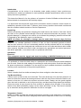
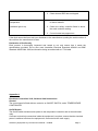
WARNING
It is detrimental for any of the substances listed below to be inside this equipment. The interior
of the bath may be damaged if exposed to any of them. Corrosion of the stainless steel and
other surfaces will be directly attributable to the presence of one or more of these substances
and will not be a defect or failure for which the manufacturer will accept responsibility.
ORGANIC
SUBSTANCES
SALT
ACIDS
MISCELLA
NEOUS
ALKAFORM
AMMONIUM
BROMIDE
ACETIC
BROMIDE
ANAESTHESIA
AMMONIUM
CHLORIDE
BORIC
CHLORINE
CARBON
CALCIUM
CHLORIDE
CARBOLIC
(PHENOL)
FLUORINE
TETRACHLORIDE
CALCIUM
HYPOCHLORITE
CHROMIC
IODINE
FORMALDEHYDE
FERRIC CHLORIDE
HYDROCYAIC
SULPHUR
DIOXIDE
LYSOL(CRESOLS
ETC)
HYDROGEN
PEROXIDE
NITRIC
TRICHLORETHYLEN
E
MAGNESIUM
CHLORIDE
OXALIC
MERCURIC
CHLORIDE
HYDROCHLORIC
POTASSIUM
PHOSPORIC
Laboratory Equipment Pty Ltd Instruction Manual – Oil Bath Page 2

CHLORIDE
POTASSIUM
HYPOCHLORITE
SULPHURIC
POTASSIUM
HYPOCHLORITE
SULPHUROUS
SODIUM CHLORIDE
TARTARIC
SODIUM
HYPOCHLORITE
Operation
1. Connect the bath to an alternating current supply of voltage specified on the rating plate.
2. Ensure the oil level is above the elements.
DANGER: THIS BATH MUST NOT BE CONNECTED TO A DIRECT POWER SUPPLY
3. Switch the MAINS on then Turn the simmerstat/thermostat or temperature controller up
as required and check the indicating lamp is illuminated.
4. An indicating lamp on the controller will illuminate when the heaters are operating.
5. Ensure the overheat cut off is set by pressing it in or the overtemperature alarm AL4 is
set above the desired operating temperature (depending on which is present).
Safety Cut/ Overtemperature
If the bath is fitted with a manual reset button, be sure this is depressed before use. If the level
is too low or runs out the switch will pop out and turn the heaters off until the reset is depressed.
If the bath is fitted with an inbuilt overheat safety protection. It must be set to slightly above the
desired setpoint temperature and will prevent overheating. It will maintain the Alarm Set Value.
Change the AL4 value to slightly above the setpoint temperature as set out in the instruction
page. The Alarm will be activated if the incubator exceeds the AL4 value or if the sensor is
broken or damaged. Adjusting the Alarm Hysterisis value will cause the incubator to cool down
by that value before it begins heating again. For example if the Alarm Hysterisis is set to 100
the incubator must cool down by 100°c below AL4 before it will begin to reheat. Where you
require the incubator to switch off completely should an alarm condition result then please
contact the manufacturer to purchase the OST100 manual over temperature reset control
system.
Maintenance
The casing is finished with stainless steel and to maintain appearance should be wiped over
with a non abrasive cleanser.
The interior is also stainless steel and may also be cleaned with a solvent
Trouble Shooting
SYMPTOM
REMEDY
No Power
(Indicator Light is off)
1. Check the bath is plugged in and power
switched on.
2. Ensure mains power supply point is
functioning by using a test appliance on
power socket.
Laboratory Equipment Pty Ltd Instruction Manual – Oil Bath Page 3

3. Check internal RCD has not tripped.
Failure to heat or maintain
temperature
(Indicator light is on)
1. Ensure the temperature controller set point
is above ambient.
2. Check the safety controller fitted is above
the main controller setting.
3. Cut out button has popped out.
If the fault cannot be found call your distributor or the manufacturer quoting the serial number of
the unit from the manufacturer’s label.
Declaration of Conformity
Each product is thoroughly inspected and tested to not only ensure that it meets the
specifications provided, but to also meet Australian Electrical Standard AS3820 and EMC
Standard AS/NZ1044:1995,and therefore being accredited with a C Tick label.
Appendix A
Eurotherm Controllers 3216, 2416 and 2404 Instructions
General
The control panel is fitted with two controls: an ON/OFF SWITCH, and a TEMPERATURE
CONTROLLER.
On/Off Switch
The On/Off switch isolates mains power to the temperature controller and to the solid state
relay.
If access to electrical connections inside the equipment is required, ensure that the electrical
power is switched off where the equipment is connected to the main supply.
Laboratory Equipment Pty Ltd Instruction Manual – Oil Bath Page 4

Temperature Controller
The Eurotherm microprocessor temperature controller has the facility for a single ramping rate
and then hold function. To set up a full program in °C/seconds/minutes/hours you must
purchase the fully programmable optioned controller.
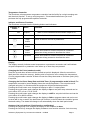
Indicator and Button Functions
The Eurotherm controller has the following buttons and indicators:
Indicator or
button
Name
Function
OP1
Output 1
When lit, this indicates that the element output is on.
ALM
Alarm 4
When lit, this indicates that an alarm condition exists.
Page
button
Press to select a new list of parameters.
Scroll
button
Press to select a new parameter in a list.
Down
button
Press and release to view the set point or a selected
parameter. Keep pressed to decrease the value.
Up button
Press and release to view the set point or a selected
parameter. Keep pressed to increase the value
Display
The display normally indicates actual temperature or parameter mnemonic and it will indicate
set point temperature or parameter value when up or down keys are pressed.
Changing the Set Point (standard model)
Press the up and down arrows until the desired set point is displayed. Allow the controller to
flash (store the value into memory). Nothing else is required to set or change the temperature.
If a non programmable controller is fitted now set the safety thermostat or set Alarm point (AL4)
if required.
Changing the Set Point, Ramp Rate and Hold Timer (if programmable model is fitted) The
temperature controller's normal display shows the actual temperature. The set point can be
changed using the /\ or \/ buttons and the equipment will hold at that temperature.
Pressing the scroll button once changes the display to oP or % output power.
Pressing the scroll button again changes the display to Sprr or set point ramp rate and can be
set to either OFF or from 1 to 60°C/min
Pressing the scroll button again changes the display to dwEll or set point hold time and can be
set to either off or 999.9 minutes.
Pressing the scroll button again changes the display to StAt or program status and can be set
to on or off. In the on status, the dwell timer will function, in the off status the controller ignores
the dwell setting. The status will change to off automatically when the dwell period ends.
Auto tune List (only perform if fault found or recalibrating)
Pressing the Page key once changes the display to the Auto tune list Atun.
Pressing the Scroll key changes the display to tune or tune function selection. Auto tune may
Laboratory Equipment Pty Ltd Instruction Manual – Oil Bath Page 5

now be selected using the /\or \/ buttons.
PID List
Pressing the Page key again changes the display to the PID List PID.
Pressing the Scroll key changes the display to Pb,ti,td,Hcb, and Lcb. The values for these
may be accessed and changed using the /\ or \/ buttons. A full description of their meanings is
in the Tuning section.
Operating the Equipment
When the equipment is first turned on the controller will carry out self checks and then start
controlling at the set point value.
Set the parameters detailed in the manual.
To reset the controller after dwell end (End) or other alarm press the PAGE and SCROLL keys
simultaneously. If a ramp dwell program is to be run again set status back to on.
When running the equipment at a new temperature that varies more than about 25% from the
previous temperature it may be necessary to run the auto tuning program to reset the PID
parameters. The equipment will overshoot the set point when running the auto tune
program especially at low temperatures.
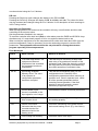
Error Messages
Alarm
What it means
What to do about it
FSH1
Full Scale High Alarm: The
equipment measured
temperature has exceeded
the equipment maximum
temperature.
This fault may be caused by a faulty solid
state relay or by exothermic reaction of the
equipment load. Reset the alarm by pressing
the Page and Scroll buttons simultaneously
and check operation of solid state relay.
EE.Er
Electrically Erasable
Memory Error: The value
of an operator or
configuration parameter
has been corrupted.
This fault will automatically take you into
configuration level. Check all of the
configuration parameters before returning to
operator level. Once in operator level, check
all of the operator parameters before
resuming normal operation. If the fault
persists or occurs frequently, contact
Laboratory Equipment Pty Ltd.
S.br
Sensor Break: Input
sensor is unreliable or the
input signal is out of range.
Check that the sensor is correctly connected.
L.br
Loop Break: The feedback
loop is open circuit.
Check that the heating and cooling circuits
are working properly.
Ld.f
Heater circuit fault:
Indication that the power
controller device has
detected a fault in the
heating circuit.
Check the functioning of the power control
device and heating circuit. (E.g. fuse failure).
LLLL
Out of range low reading
Check the value of the input
Laboratory Equipment Pty Ltd Instruction Manual – Oil Bath Page 6

HHHH
Out of range high reading
Check the value of the input
Err1
Error 1: ROM self test fail
Return the controller for repair
Err2
Error 2: RAM self test fail
Return the controller for repair
Err3
Error 3: Watchdog fail
Return the controller for repair
Err4
Error 4: Keyboard failure
Stuck button or a button
was pressed during power
up.
Switch the power off and then on without
touching any of the controller buttons.
Tuning
In tuning, you match the characteristics of the controller to those of the process being controlled
in order to obtain good control. Good control means:
● Stable, ‘straight line’ control of the temperature at set point without fluctuation.
● No overshoot, or undershoot, of the temperature set point.
● Quick response to deviations from the set point caused by external disturbances,
thereby rapidly restoring the temperature to the set point value.
Tuning involves calculating and setting the value of the parameters listed in Table 4 1. These
parameters appear in the ‘Pid’ list.
Table 4 1 Tuning parameters
Parameter
Code
Meaning or Function
Proportional
band
Pb
The bandwidth, in display units, over which the output power is
proportioned between minimum and maximum.
Integral time
ti
Determines the time taken by the controller to remove
steady state error signals.
Derivative
time
td
Determines how strongly the controller will react to the
rate of change of the measured value.
High
Cutback
Hcb
The number of display units, above set point, at which the
controller will increase the output power, in order to prevent
undershoot on cool down.
Low
cutback
Lcb
The number of display units, below set point, at which the
controller will cutback the output power, in order to prevent
overshoot on heat up.
Relative
cool
gain
rEL
Only present if cooling has been configured and a module is
fitted. Sets the cooling proportional band: divide the Pb value
by the rEL value.
AUTOMATIC TUNING
TWO AUTOMATIC TUNING PROCEDURES ARE PROVIDED IN THE 2408 AND 2404: ●A one shot tuner,
which automatically sets up the initial values of the parameters listed in Table 4 1 on the
Laboratory Equipment Pty Ltd Instruction Manual – Oil Bath Page 7

previous page.
●Adaptive tuning, which continuously monitors the error from set point and modifies the PID
values, if necessary.
One shot Tuning
The ‘one shot’ tuner works by switching the output on and off to induce an oscillation in the
measured value. From the amplitude and period of the oscillation, it calculates the tuning
parameter values.
If the process cannot tolerate full heating or cooling being applied during tuning, then the level
of heating or cooling can be restricted by setting the heating and cooling power limits in the ‘oP’
list. However, the measured value must oscillate to some degree for the tuner to be able to
calculate values.
A One shot Tune can be performed at any time, but normally it is performed only once during
the initial commissioning of the process. However, if the process under control subsequently
becomes unstable (because its characteristics have changed), you can re tune again for the
new conditions.
It is best to start tuning with the process at ambient temperature. This allows the tuner to
calculate more accurately the low cutback and high cutback values which restrict the amount of
overshoot, or undershoot.
How to tune
1. Set the set point to the value at which you will normally operate the process. 2. In the
‘Atun’ list, select ‘tunE’ and set it to ‘on’.
3. Press the Page and Scroll buttons together to return to the Home display. The display will
flash ‘tunE’ to indicate that tuning is in progress.
4. The controller induces an oscillation in the temperature by first turning the heating on,
and then off. The first cycle is not complete until the measured value has reached the
required set point.
5. After two cycles of oscillation the tuning is completed and the tuner switches itself off.
6. The controller then calculates the tuning parameters listed in Table 4 1 and resumes
normal control action.
If you want ‘Proportional only’, ‘PD’, or ‘PI’ control, you should set the ‘ti’ or ‘td’ parameters to
OFF before commencing the tuning cycle. The tuner will leave them off and will not calculate a
value for them.
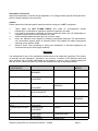
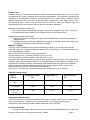
Typical automatic tuning cycle
Calculation of the cutback values
Low cutback and High cutback are a value that restrict the amount of overshoot, or
undershoot, that occurs during large step changes in temperature (for example, under start up
conditions). If either low cutback, or high cutback, is set to ‘Auto’ the values are fixed at three
times the proportional band, and are not changed during automatic tuning.
Laboratory Equipment Pty Ltd Instruction Manual – Oil Bath Page 8

Adaptive tune
Adaptive tuning is a background algorithm, which continuously monitors the error from set point
and analyses the control response during process disturbances. If the algorithm recognises an
oscillatory, or under damped response, it recalculates the Pb, ti and td values. Adaptive tune is
triggered whenever the error from set point exceeds a trigger level. This trigger level is set in
the parameter ‘drA.t’, which is found in the Auto tune list. The value is in display units. It is
automatically set by the controller, but can also be manually re adjusted.
Adaptive tune should be used with:
1. Processes whose characteristics change as a result of changes in the load, or set point.
2. Processes that cannot tolerate the oscillation induced by a One shot tune.
Adaptive tune should not be used:
1. Where the process is subjected to regular external disturbances that could mislead the
adaptive tuner.
2. On highly interactive multi loop applications. However, moderately interactive loops, such
as multi zone extruders, should not give a problem.
MANUAL TUNING
If for any reason automatic tuning gives unsatisfactory results, you can tune the controller
manually. There are a number of standard methods for manual tuning. The one described here
is the Ziegler Nichols method.
With the process at its normal running temperature:
Set the Integral Time ‘ti’ and the Derivative Time ‘td’ to OFF.
Set High Cutback and Low Cutback, ‘Hcb’ and ‘Lcb’, to ‘Auto’.
Ignore the fact that the temperature may not settle precisely at the set point. If the temperature
is stable, reduce the proportional band ‘Pb’ so that the temperature just starts to oscillate. If the
temperature is already oscillating, increase the proportional band until it just stops oscillating.
Allow enough time between each adjustment for the loop to stabilise. Make a note of the
proportional band value ‘B’ and the period of oscillation ‘T’.
Set the Pb, ti, td parameter values according to the calculations given in Table 4 2.
Table 4 2 Tuning values
Type of
control
Proportional band
‘Pb’
Integral time ‘ti’
Derivative time
‘td’
Proportional
only
2xB
OFF
OFF
P + I control
2.2xB
0.8xT
OFF
P + I + D
control
1.7xB
0.5xT
0.12xT
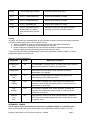
Setting the cutback values
The above procedure sets up the parameters for optimum steady state control. If unacceptable
levels of overshoot or undershoot occur during start-up, or for large step changes in
temperature, then manually set the cutback parameters ‘Lcb’ and ‘Hcb’.
Proceed as follows:
1. Set the low and high cutback values to three proportional bandwidths (that is to say, Lcb
Laboratory Equipment Pty Ltd Instruction Manual – Oil Bath Page 9

= Hcb = 3 x Pb).
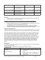
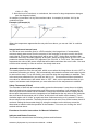
2. Note the level of overshoot, or undershoot, that occurs for large temperature changes
(see the diagrams below).
In example (a) increase ‘Lcb’ by the overshoot value. In example (b) reduce ‘Lcb’ by the
undershoot value.
Example (a) Example (b)
Where the temperature approaches the set point from above, you can set ‘Hcb’ in a similar
manner.
Integral action and manual reset
In a full three term controller (that is, a PID controller), the integral term ‘ti’ automatically
removes steady state errors from the set point. If the controller is set up to work in two term
mode (that is, PD mode), the integral term will be set to ‘OFF’. Under these conditions the
measured value may not settle precisely at set point. When the integral term is set to ‘OFF’ the
parameter manual reset (code ‘rES’) appears in the ‘Pid LiSt’ in ‘FuLL’ level. This parameter
represents the value of the power output that will be delivered when the error is zero. You must
set this value manually in order to remove the steady state error.
Automatic droop compensation (Adc)
The steady state error from the set point, which occurs when the integral term is set to ‘OFF’ is
sometimes referred to as ‘droop’. ‘Adc’ automatically calculates the manual reset value in order
to remove this droop. To use this facility, you must first allow the temperature to stabilise. Then,
in the auto tune parameter list, you must set ‘Adc’ to ‘on’. The controller will then calculate a
new value for manual reset, and switch ‘Adc’ to ‘OFF’. ‘Adc’ can be repeated as often as you
require, but between each adjustment you must allow time for the temperature to stabilise.
Safety Thermostat (if fitted)
The chamber is fitted with an overheat safety protection thermostat. It must be set to slightly
above the desired set point temperature and will prevent overheating. It will maintain the set
value only and will not switch off the chamber. Change the thermostat value to slightly above
the set point temperature once the temperature has stabilized at the set value on the controller,
then turn back the thermostat until it “clicks” at this point it will switch off the heaters. Turn it
clockwise again until it “clicks” on again and then continues turning so it is around 5°C above
the set value on the controller. The safety thermostat is now set to turn off the heaters should it
overheat. Setting the thermostat simply by using the numbers on the dial may cause the
thermostat to interfere with the operation of the chamber. To be sure, set it using the “click”
method outlined above.
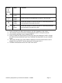
Eurotherm Controller Instructions for Manual Calibration
Indicator and Button Functions
The Eurotherm controller has the following buttons and indicators:
Laboratory Equipment Pty Ltd Instruction Manual – Oil Bath Page 10

Indicat
or
or
button
Name
Function
Page
button
Press to select a new list of parameters. (Left most key)
Scroll
button
Press to select a new parameter in a list.(2nd key from left)
Down
button
Press and release to view the set point or a selected parameter.
Keep pressed to decrease the value.
Up
button
Press and release to view the set point or a selected parameter.
Keep pressed to increase the value
1. Press and hold in the Menu (left most key) until LVL3 appears on the screen.
2. The controller will then ask for the COD (password) enter 3 using the up arrow.
3. If successful push Menu once to display INPUT.
4. Press (not hold) the Scroll buttons (2nd key from left) until it displays PV.OFS. Change
this value using up and down keys only to calibrate the temperature on your external
logger.
5. Then press the Menu key until ACCES is displayed. Press the Scroll button once to
display LVL3 and GOTO. Use the down arrow to change to LVL1.
6. Controller will flash and return to the main user screen.
Laboratory Equipment Pty Ltd Instruction Manual – Oil Bath Page 11
-
 1
1
-
 2
2
-
 3
3
-
 4
4
-
 5
5
-
 6
6
-
 7
7
-
 8
8
-
 9
9
-
 10
10
-
 11
11
-
 12
12


Ask a question and I''ll find the answer in the document
Finding information in a document is now easier with AI
Related papers


Other documents
-
Eurotherm 2416 Owner's manual
-
Eurotherm 2204e/2208 Owner's manual
-
-
-
-
Eurotherm 2132 / 2116 User guide
-
-
 Thermcraft XST-2-0-12-1V1-E29 User manual
-
 Marathon Computer Computer Monitor AACC 2000 User manual
-

