Page is loading ...

www.ti.com
1 INTRODUCTION
1.1 FEATURES 1.2 APPLICATIONS
1.3 DESCRIPTION
HostSystem
SingleCellLi-Ion
BatteryPack
PACK-
PROTECTION
IC
CHG
DSG
Temp
Sense
Battery
Good
Current
Sense
I2C
T
LDO
PACK+
Voltage
Sense
Battery
Low
Warning
FETs
bq27500/1
RID
RID
Sense*
*bq27501Only
Power
Management
Controller
bq27500
bq27501
System-Side Impedance Track™ Fuel Gauge
SLUS785 – SEPTEMBER 2007
• Battery Fuel Gauge for 1-Series Li-Ion
• Smartphones
Applications
• PDAs
• Resides on System Main Board
• Digital Still and Video Cameras
– Works with Embedded or Removable
• Handheld Terminals
Battery Packs
• MP3 or Multimedia Players
• Two Varieties
– bq27500: Uses PACK+, PACK-, and T
Battery Terminals
– bq27501: Includes Battery Pack ID Resistor
(RID) Terminal
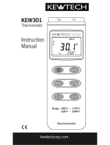
The Texas Instruments bq27500/01 System-Side
Li-Ion Battery Fuel Gauge is a micro-controller
• Micro-Controller Peripheral Provides:
peripheral that provides fuel gauging for single cell
– Accurate Battery Fuel Gauging
Li-Ion battery packs. The device requires little system
– Internal Temperature Sensor for System
micro-controller firmware development. The
Temperature Reporting
bq27500/01 resides on the system’s main board, and
– Battery Low Interrupt Warning
manages an embedded battery (non-removable) or a
– Battery Insertion Indicator
removable battery pack.
– Battery ID Detection
– 96 bytes of Non-Volatile Scratch Pad
The bq27500/01 uses the patented Impedance
FLASH
Track™ algorithm for fuel gauging, and provides
information such as remaining battery capacity
• Battery Fuel Gauge Based on Patented
(mAh), state-of-charge (%), run-time to empty (min.),
Impedance Track™ Technology
battery voltage (mV), and temperature ( ° C).
– Models the Battery Discharge Curve for
Accurate Time-to-Empty Predictions
Battery fuel gauging with the bq27500 requires only
– Automatically Adjusts for Battery Aging,
PACK+ (P+), PACK- (P-), and Thermistor (T)
Battery Self Discharge, and
connections to a removable battery pack or
Temperature/Rate Inefficiencies
embedded battery circuit. The bq27501 works with
– Low Value Sense Resistor (10m Ω or Less)
identification resistors in battery packs, to gauge
• I
2
C™ Interface for Connection to System
batteries of different fundamental chemistries and/or
Micro-Controller Port
significantly different rated capacities.
• 12-Pin 2,5 mm × 4,0 mm SON Package
TYPICAL APPLICATION
Please be aware that an important notice concerning availability, standard warranty, and use in critical applications of Texas
Instruments semiconductor products and disclaimers thereto appears at the end of this document.
Impedance Track is a trademark of Texas Instruments.
I
2
C is a trademark of Philips Electronics.
UNLESS OTHERWISE NOTED this document contains
Copyright © 2007, Texas Instruments Incorporated
PRODUCTION DATA information current as of publication date.
Products conform to specifications per the terms of Texas
Instruments standard warranty. Production processing does not
necessarily include testing of all parameters.

www.ti.com
Contents
bq27500
bq27501
System-Side Impedance Track™ Fuel Gauge
SLUS785 – SEPTEMBER 2007
These devices have limited built-in ESD protection. The leads should be shorted together or the device placed in
conductive foam during storage or handling to prevent electrostatic damage to the MOS gates.
1 INTRODUCTION .......................................... 1 4.2 DATA FLASH INTERFACE ......................... 16
1.1 FEATURES ........................................... 1 4.3 MANUFACTURER INFORMATION BLOCKS ...... 17
1.2 APPLICATIONS ...................................... 1 4.4 ACCESS MODES ................................... 17
1.3 DESCRIPTION ....................................... 1 4.5 SEALING/UNSEALING DATA FLASH .............. 17
2 DEVICE INFORMATION ................................. 3 4.6 DATA FLASH SUMMARY ........................... 18
2.1 AVAILABLE OPTIONS ............................... 3 5 FUNCTIONAL DESCRIPTION ........................ 20
2.2 PIN DIAGRAMS ...................................... 3 5.1 FUEL GAUGING .................................... 20
2.3 TERMINAL FUNCTIONS ............................. 3 5.2 IMPEDANCE TRACK™ VARIABLES ............... 21
3 ELECTRICAL SPECIFICATIONS ...................... 4 5.3 DETAILED DESCRIPTION OF DEDICATED PINS . 23
3.1 ABSOLUTE MAXIMUM RATINGS ................... 4 5.4 TEMPERATURE MEASUREMENT ................. 26
3.2 RECOMMENDED OPERATING CONDITIONS ...... 4 5.5 OVERTEMPERATURE INDICATION ............... 26
5.6 CHARGING AND CHARGE-TERMINATION
3.3 POWER-ON RESET .................................. 4
INDICATION ......................................... 26
3.4 INTERNAL TEMPERATURE SENSOR
CHARACTERISTICS ................................. 5 5.7 POWER MODES .................................... 27
3.5 HIGH FREQUENCY OSCILLATOR .................. 5 5.8 POWER CONTROL ................................. 29
3.6 LOW FREQUENCY OSCILLATOR ................... 5 5.9 AUTOCALIBRATION ................................ 30
3.7 INTEGRATING ADC (COULOMB COUNTER)
6 APPLICATION-SPECIFIC INFORMATION .......... 31
CHARACTERISTICS ................................. 5
6.1 BATTERY PROFILE STORAGE AND SELECTION 31
3.8 ADC (TEMPERATURE AND CELL
6.2 APPLICATION-SPECIFIC FLOW AND CONTROL . 31
MEASUREMENT) CHARACTERISTICS ............. 5
7 COMMUNICATIONS .................................... 33
3.9 DATA FLASH MEMORY CHARACTERISTICS ...... 6
7.1 I
2
C INTERFACE ..................................... 33
3.10 I
2
C-COMPATIBLE INTERFACE COMMUNICATION
8 REFERENCE SCHEMATICS .......................... 34
TIMING CHARACTERISTICS ........................ 6
8.1 SCHEMATIC ........................................ 34
4 GENERAL DESCRIPTION .............................. 8
4.1 DATA COMMANDS .................................. 9
2 Contents Submit Documentation Feedback

www.ti.com
2 DEVICE INFORMATION
2.1 AVAILABLE OPTIONS
2.2 PIN DIAGRAMS
BAT
V
SS
SRN
SRP
V
CC
BAT_GD
SDA
SCL
1
2
3
4
5
6
12
11
10
9
8
7
BAT_LOW_
TS
1
2
3
4
5
6
12
11
10
9
8
7
BI/TOUT
BAT
V
SS
V
CC
BAT_LOW_
TS
BI/TOUT
NC
SRN
SRP
BAT_GD
SDA
SCL
RID
bq27500
bq27501
2.3 TERMINAL FUNCTIONS
bq27500
bq27501
System-Side Impedance Track™ Fuel Gauge
SLUS785 – SEPTEMBER 2007
COMMUNICATION TAPE and REEL
PART NUMBER PACKAGE
(1)
T
A
FORMAT QUANTITY
bq27500DRZR 3000
bq27500DRZT 300
12-pin, 2,5 mm x 4,0 mm
–40 ° C to 85 ° C I
2
C
SON
bq27501DRZR
(2)
3000
bq27501DRZT
(2)
300
(1) For the most current package and ordering information, see the Package Option Addendum at the end of this document, or see the TI
website at www.ti.com .
(2) Product Preview
TERMINAL
I/O
(1)
DESCRIPTION
NAME NAME
PIN NO.
bq27500 bq27501
Battery Low output indicator. Active high by default, though polarity can be configured
1 BAT_LOW BAT_LOW O
through the [BATL_POL] in Operation Configuration Push-pull output.
Battery-insertion detection input. Power pin for pack thermistor network. Thermistor
2 BI/TOUT BI/TOUT I/O
multiplexer control pin. Open-drain I/O. use with pull-up resistor > 1M Ω (1.8M Ω typical)
3 TS TS P Pack thermistor voltage sense (use 103AT-type thermistor). ADC input.
4 BAT BAT I Cell-voltage measurement input. ADC input.
5 V
CC
V
CC
P Processor power input. Decouple with 0.1 μ F capacitor, minimum.
6 V
SS
V
SS
P Device ground.
Analog input pin connected to the internal coulomb-counter where SRP is nearest the
7 SRP SRP IA
CELL- connection. Connect to 5-20m Ω sense resistor.
Analog input pin connected to the internal coulomb-counter where SRN is nearest the
8 SRN SRN IA
PACK- connection. Connect to 5-20m Ω sense resistor.
No connection (bq27500). Resistor ID input (bq27501). Analog input with current sourcing
9 NC RID –, I
capabilities.
Slave I
2
C serial communications data line for communication with system ( Master).
10 SDA SDA I/O
Open-drain I/O. Use with 10k Ω pull-up resistor (typical).
Slave I
2
C serial communications clock input line for communication with system ( Master).
11 SCL SCL I
Open-drain I/O. Use with 10k Ω pull-up resistor (typical).
Battery Good indicator. Active low by default, though polarity can be configured through
12 BAT_GD BAT_GD O
the [BATG_POL] of Operation Configuration. Open-drain output.
(1) I/O = Digital Input/Output, IA = Analog Input, P = Power Connection
Submit Documentation Feedback DEVICE INFORMATION 3

www.ti.com
3 ELECTRICAL SPECIFICATIONS
3.1 ABSOLUTE MAXIMUM RATINGS
3.2 RECOMMENDED OPERATING CONDITIONS
3.3 POWER-ON RESET
bq27500
bq27501
System-Side Impedance Track™ Fuel Gauge
SLUS785 – SEPTEMBER 2007
over operating free-air temperature range (unless otherwise noted)
(1)
PARAMETER VALUE UNIT
V
CC
Supply voltage range –0.3 to 2.75 V
V
IOD
Open-drain I/O pins (BI_TOUT, SDA, SDL, BAT_GD) –0.3 to 6 V
V
BAT
BAT input pin –0.3 to +6
V
I
Input voltage range to all other pins (TS, SRP, SRN, RID [bq27501 only], NC –0.3 to V
CC
+ 0.3 V
[bq27500 only])
1 kV
ESD Human Body Model (HMB)
2 kV
T
F
Functional temperature range –40 to 100 ° C
T
STG
Storage temperature range –65 to 150 ° C
(1) Stresses beyond those listed under absolute maximum ratings may cause permanent damage to the device. These are stress ratings
only, and functional operation of the device at these or any other conditions beyond those indicated under recommended operating
conditions is not implied. Exposure to absolute-maximum-rated conditions for extended periods may affect device reliability.
T
A
= 25 ° C, V
CC
= 2.5 V (unless otherwise noted)
PARAMETER TEST CONDITIONS MIN TYP MAX UNIT
V
CC
Supply Voltage 2.4 2.5 2.6 V
I
CC
Normal operating mode current
(1)
95 μ A
I
SLP
Low-power storage mode current
(2)
15 μ A
I
CC
Hibernate operating mode current
(3)
2 μ A
V
OL
Output voltage low (SDA, BAT_LOW, BI/TOUT) I
OL
= 0.5 mA 0.4 V
V
OH(PP)
Output high voltage (BAT_LOW) I
OH
= –1 mA V
CC
–0.5 V
External pull-up resistor
V
OH(OD)
Output high voltage (SDA, SCL, BI/TOUT) V
CC
–0.5 V
connected to V
CC
V
IL
Input voltage low (SDA, SCL) –0.3 0.8
V
V
IH(OD)
Input voltage high (SDA, SCL, BI/TOUT) 2 6
C
IN
Input capacitance 5 pF
V
A1
Input voltage range (TS, RID [bq27501 only]) V
SS
–0.125 2 V
V
A2
Input voltage range (BAT) V
SS
–0.125 5 V
V
A3
Input voltage range (SRP, SRN) V
SS
–0.125 0.125 V
t
PUCD
Power up communication delay 250 ms
T
A
Operating free-air temperature range –40 85 ° C
(1) High level of system activity.
(2) Low level of system activity.
(3) Fuel gauge algorithm power inactive. Only able to receive I
2
C communication.
T
A
= –40 ° C to 85 ° C, Typical Values at T
A
= 25 ° C and V
BAT
= 3.6 V (unless otherwise noted)
PARAMETER TEST CONDITIONS MIN TYP MAX UNIT
V
IT+
Positive-going battery voltage input at V
CC
2.09 2.20 2.31 V
V
HYS
45 115 185 mV
ELECTRICAL SPECIFICATIONS4 Submit Documentation Feedback

www.ti.com
3.4 INTERNAL TEMPERATURE SENSOR CHARACTERISTICS
3.5 HIGH FREQUENCY OSCILLATOR
3.6 LOW FREQUENCY OSCILLATOR
3.7 INTEGRATING ADC (COULOMB COUNTER) CHARACTERISTICS
3.8 ADC (TEMPERATURE AND CELL MEASUREMENT) CHARACTERISTICS
bq27500
bq27501
System-Side Impedance Track™ Fuel Gauge
SLUS785 – SEPTEMBER 2007
T
A
= –40 ° C to 85 ° C, 2.4 V < V
CC
< 2.6 V; Typical Values at T
A
= 25 ° C and V
CC
= 2.5 V (unless otherwise noted)
PARAMETER TEST CONDITIONS MIN TYP MAX UNIT
G
TEMP
Temperature sensor voltage gain –2.0 mV/ ° C
T
A
= –40 ° C to 85 ° C, 2.4 V < V
CC
< 2.6 V; Typical Values at T
A
= 25 ° C and V
CC
= 2.5 V (unless otherwise noted)
PARAMETER TEST CONDITIONS MIN TYP MAX UNIT
f
OSC
Operating frequency 2.097 MHz
T
A
= 0 ° C to 60 ° C –2.0% 0.38% 2.0%
f
EIO
Frequency error
(1) (2)
T
A
= –20 ° C to 70 ° C –3.0% 0.38% 3.0%
T
A
= –40 ° C to 85 ° C –4.5% 0.38% 4.5%
t
SXO
Start-up time
(3)
2.5 5 ms
(1) The frequency error is measured from 2.097 MHz.
(2) The frequency drift is included and measured from the trimmed frequency at V
CC
= 2.5V, T
A
= 25 ° C.
(3) The startup time is defined as the time it takes for the oscillator output frequency to be ± 3%.
T
A
= –40 ° C to 85 ° C, 2.4 V < V
CC
< 2.6 V; Typical Values at T
A
= 25 ° C and V
CC
= 2.5 V (unless otherwise noted)
PARAMETER TEST CONDITIONS MIN TYP MAX UNIT
f
LOSC
Operating frequency 32.768 kHz
T
A
= 0 ° C to 60 ° C –1.5% 0.25% 1.5%
f
LEIO
Frequency error
(1) (2)
T
A
= –20 ° C to 70 ° C –2.5% 0.25% 2.5%
T
A
= –40 ° C to 85 ° C –4.0% 0.25% 4.0%
t
LSXO
Start-up time
(3)
500 μ s
(1) The frequency drift is included and measured from the trimmed frequency at V
CC
= 2.5V, T
A
= 25 ° C.
(2) The frequency error is measured from 32.768 kHz.
(3) The startup time is defined as the time it takes for the oscillator output frequency to be ± 3%.
T
A
= –40 ° C to 85 ° C, 2.4 V < V
CC
< 2.6 V; Typical Values at T
A
= 25 ° C and V
CC
= 2.5 V (unless otherwise noted)
PARAMETER TEST CONDITIONS MIN TYP MAX UNIT
V
SR_IN
Input voltage range, V
(SRN)
and V
(SRP)
V
SR
= V
(SRN)
– V
(SRP)
–0.125 0.125 V
t
SR_CONV
Conversion time Single conversion 1 s
Resolution 14 15 bits
Before calibration 1 mV
V
SR_OS
Input offset
After calibration 10 μ V
INL Integral nonlinearity error ± 0.007 ± 0.034 % FSR
Z
SR_IN
Effective input resistance
(1)
2.5 M Ω
I
SR_LKG
Input leakage current
(1)
0.3 μ A
(1) Specified by design. Not tested in production.
T
A
= –40 ° C to 85 ° C, 2.4 V < V
CC
< 2.6 V; Typical Values at T
A
= 25 ° C and V
CC
= 2.5 V (unless otherwise noted)
PARAMETER TEST CONDITIONS MIN TYP MAX UNIT
V
ADC_IN
Input voltage range –0.2 1 V
Submit Documentation Feedback ELECTRICAL SPECIFICATIONS 5

www.ti.com
3.9 DATA FLASH MEMORY CHARACTERISTICS
3.10 I
2
C-COMPATIBLE INTERFACE COMMUNICATION TIMING CHARACTERISTICS
bq27500
bq27501
System-Side Impedance Track™ Fuel Gauge
SLUS785 – SEPTEMBER 2007
ADC (TEMPERATURE AND CELL MEASUREMENT) CHARACTERISTICS (continued)
T
A
= –40 ° C to 85 ° C, 2.4 V < V
CC
< 2.6 V; Typical Values at T
A
= 25 ° C and V
CC
= 2.5 V (unless otherwise noted)
PARAMETER TEST CONDITIONS MIN TYP MAX UNIT
t
ADC_CONV
Conversion time 125 ms
Resolution 14 15 bits
V
ADC_OS
Input offset 1 mV
Z
ADC1
Effective input resistance (TS, RID 8 M Ω
[bq27501 only])
bq27500/1 not measuring cell voltage 8 M Ω
Z
ADC2
Effective input resistance (BAT)
(1)
bq27500/1 measuging cell voltage 100 k Ω
I
ADC_LKG
Input Leakage Current
(1)
0.3 μ A
(1) Specified by design. Not tested in production.
T
A
= –40 ° C to 85 ° C, 2.4 V < V
CC
< 2.6 V; Typical Values at T
A
= 25 ° C and V
CC
= 2.5 V (unless otherwise noted)
PARAMETER TEST CONDITIONS MIN TYP MAX UNIT
t
ON
Data retention See
(1)
10
(1)
Years
Flash programming write-cycles See
(1)
20,000 Cycles
t
WORDPROG
Word programming time See
(1)
2 ms
I
CCPROG
Flash-write supply current 5 10 mA
(1) Specified by design. Not production tested
T
A
= –40 ° C to 85 ° C, 2.4 V < V
CC
< 2.6 V; Typical Values at T
A
= 25 ° C and V
CC
= 2.5 V (unless otherwise noted)
PARAMETER TEST CONDITIONS MIN TYP MAX UNIT
t
r
SCL/SDA rise time 1 μ s
t
f
SCL/SDA fall time 300 ns
t
w(H)
SCL pulse width (high) 4 μ s
t
w(L)
SCL pulse width (low) 4.7 μ s
t
su(STA)
Setup for repeated start 4.7 μ s
t
d(STA)
Start to first falling edge of SCL 4 μ s
t
su(DAT)
Data setup time 250 ns
Receive mode 0
t
h(DAT)
Data hold time ns
Transmit mode 300
t
su(STOP)
Setup time for stop 4 μ s
t
BUF
Bus free time between stop and start 4.7 μ s
f
SCL
Clock frequency 10 100 kHz
t
BUSERR
Bus error timeout 17.3 21.2 s
ELECTRICAL SPECIFICATIONS6 Submit Documentation Feedback


www.ti.com
4 GENERAL DESCRIPTION
bq27500
bq27501
System-Side Impedance Track™ Fuel Gauge
SLUS785 – SEPTEMBER 2007
The bq27500/1 accurately predicts the battery capacity and other operational characteristics of a single
Li-based rechargeable cell. It can be interrogated by a system processor to provide cell information, such
as State-of-Charge (SOC), Time-to-Empty (TTE) and Time-to-Full (TTF).
Information is accessed through a series of commands, called Standard Commands. Further capabilities
are provided by the additional Extended Commands set. Both sets of commands, indicated by the general
format Command( ), are used to read and write information contained within the bq27500/1 control and
status registers, as well as its data flash locations. Commands are sent from system to gauge using the
bq27500/1’s I
2
C serial communications engine, and can be executed during application development,
pack manufacture, or end-equipment operation.
Cell information is stored in the bq27500/1 in non-volatile flash memory. Many of these data flash
locations are accessible during application development. They cannot be accessed directly during
end-equipment operation. Access to these locations is achieved by either use of the bq27500/1's
companion evaluation software, through individual commands, or through a sequence of data-flash-access
commands. To access a desired data flash location, the correct data flash subclass and offset must be
known.
The bq27500/1 provides 96 bytes of user-programmable data flash memory, partitioned into 3 32-byte
blocks: Manufacturer Info Block A, Manufacturer Info Block B, and Manufacturer Info Block C. This
data space is accessed through a data flash interface. For specifics on accessing the data flash, see
Section 4.3 Manufacturer Information Blocks.
The key to the bq27500/1’s high-accuracy gas gauging prediction is Texas Instrument’s proprietary
Impedance Track™ algorithm. This algorithm uses cell measurements, characteristics, and properties to
create state-of-charge predictions that can achieve less than 1% error across a wide variety of operating
conditions and over the lifetime of the battery.
The bq27500/1 measures charge/discharge activity by monitoring the voltage across a small-value series
sense resistor (5 m Ω to 20 m Ω typ.) located between the system's Vss and the battery’s PACK– terminal.
When a cell is attached to the bq27500/1, cell impedance is computed, based on cell current, cell Open
Circuit Voltage (OCV), and cell voltage under loading conditions.
The bq27500/1 can use an NTC thermistor (default is Semitec 103AT) for temperature measurement, or
can also be configured to use its internal temperature sensor. The bq27500/1 uses temperature to monitor
the battery-pack environment, which is used for fuel gauging and cell protection functionality.
To minimize power consumption, the bq27500/1 has several power modes: NORMAL, SLEEP,
HIBERNATE, and BAT INSERT CHECK. The bq27500/1 passes automatically between these modes,
depending upon the occurrence of specific events, though a system processor can initiate some of these
modes directly. More details can be found in the Section 5.7 POWER MODES.
NOTE
FORMATTING CONVENTIONS IN THIS DOCUMENT:
Commands: italics with parentheses and no breaking spaces, e.g. RemainingCapacity( ).
Data Flash: italics, bold, and breaking spaces, e.g. Design Capacity
Register Bits and Flags: brackets only, e.g. [TDA]
Data Flash Bits: italics and bold, e.g: [LED1]
Modes and states: ALL CAPITALS, e.g. UNSEALED mode.
8 GENERAL DESCRIPTION Submit Documentation Feedback

www.ti.com
4.1 DATA COMMANDS
4.1.1 STANDARD DATA COMMANDS
bq27500
bq27501
System-Side Impedance Track™ Fuel Gauge
SLUS785 – SEPTEMBER 2007
The bq27500/1 uses a series of 2-byte standard commands to enable system reading and writing of
battery information. Each standard command has an associated command-code pair, as indicated in
Table 4-1 . Because each command consists of two bytes of data, two consecutive I
2
C transmissions must
be executed both to initiate the command function, and to read or write the corresponding two bytes of
data. Additional options for transferring data, such as spooling, are described in Section 7.1 I
2
C
INTERFACE. Standard commands are accessible in NORMAL operation. Read/Write permissions depend
on the active access mode, SEALED or UNSEALED (for details on the SEALED and UNSEALED states,
see Section 4.4 Access Modes).
Table 4-1. Standard Commands
COMMAND SEALED UNSEALED
NAME UNITS
CODE ACCESS ACCESS
Control( ) CNTL 0x00 / 0x01 N/A R/W R/W
AtRate( ) AR 0x02 / 0x03 mA R/W R/W
AtRateTimeToEmpty( ) ARTTE 0x04 / 0x05 Minutes R R
Temperature( ) TEMP 0x06 / 0x07 0.1 ° K R R
Voltage( ) VOLT 0x08 / 0x09 mV R R
Flags( ) FLAGS 0x0a / 0x0b N/A R R
NominalAvailableCapacity( ) NAC 0x0c / 0x0d mAh R R
FullAvailableCapacity( ) FAC 0x0e / 0x0f mAh R R
RemainingCapacity( ) RM 0x10 / 0x11 mAh R R
FullChargeCapacity( ) FCC 0x12 / 0x13 mAh R R
AverageCurrent( ) AI 0x14 / 0x15 mA R R
TimeToEmpty( ) TTE 0x16 / 0x17 Minutes R R
TimeToFull( ) TTF 0x18 / 0x19 Minutes R R
StandbyCurrent( ) SI 0x1a / 0x1b mA R R
StandbyTimeToEmpty( ) STTE 0x1c / 0x1d Minutes R R
MaxLoadCurrent( ) MLI 0x1e / 0x1f mA R R
MaxLoadTimeToEmpty( ) MLTTE 0x20 / 0x21 Minutes R R
AvailableEnergy( ) AE 0x22 / 0x23 10mWhr R R
AveragePower( ) AP 0x24 / 0x25 10mW R R
TimeToEmptyAtConstantPower( ) TTECP 0x26 / 0x27 Minutes R R
Reserved RSVD 0x28 / 0x29 N/A R R
CycleCount( ) CC 0x2a / 0x2b Counts R R
StateOfCharge( ) SOC 0x2c / 0x2d % R R
Submit Documentation Feedback GENERAL DESCRIPTION 9

www.ti.com
bq27500
bq27501
System-Side Impedance Track™ Fuel Gauge
SLUS785 – SEPTEMBER 2007
4.1.1.1 Control( ): 0x00/0x01
Issuing a Control( ) command requires a subsequent two-byte sub-command. These additional bytes
specify the particular control function desired. The Control( ) command allows the system to control
specific features of the bq27500 during normal operation and additional features when the bq27500/1 is in
different access modes, as described in Table 4-2 .
Table 4-2. Control( ) Subcommands
CNTL SEALED
CNTL FUNCTION DESCRIPTION
DATA ACCESS
CONTROL STATUS 0x0000 Yes Reports the status of DF Checksum, Hibernate, IT, etc.
DEVICE TYPE 0x0001 Yes Reports the device type (eg: "bq27500")
FW VERSION 0x0002 Yes Reports the firmware version on the device type
HW VERSION 0x0003 Yes Reports the hardware version of the device type
Reserved 0x0004 No Not to be used
RESET DATA 0x0005 No Returns reset data
Reserved 0x0006 No Not to be used
PREV_MACWRITE 0x0007 No Returns previous MAC command code
Reports the chemical identifier of the Impedance Track™
CHEMID 0x0008 Yes
configuration
BOARD OFFSET 0x0009 No Forces the device Board Offset to be measured and stored
CC INT OFFSET 0x000b No Forces the device to measure and store the internal CC offset
SET HIBERNATE 0x0011 Yes Forces DF:Pack Configuration [HIBERNATE] to 1
CLEAR HIBERNATE 0x0012 Yes Forces DF:Pack Configuration [HIBERNATE] to 0
SEALED 0x0020 No Places the bq27500/1 in SEALED access mode
IT ENABLE 0x0021 No Enables the Impedance Track™ algorithm
IFCHECKSUM 0x0022 No Reports the instruction flash checksum
CALMODE 0x0040 No Places the bq27500/1 in calibration mode
RESET 0x0041 No Forces a full reset of the bq27500/1
4.1.1.1.1 CONTROL STATUS: 0X0000
Instructs the gas gauge to return status information to Control addresses 0x00/0x01. The status word
includes the following information.
Table 4-3. CONTROL STATUS Bit Definitions
Flags( ) bit7 bit6 bit5 bit4 bit3 bit2 bit1 bit0
High Byte – FAS SS - CCA BCA – –
Low Byte – HIBERNATE – SLEEP LDMD RUP_DIS VOK QEN
FAS = Status bit indicating the bq27500/1 is in FULL ACCESS SEALED state. Active when set.
SS = Status bit indicating the bq27500/1 is in SEALED State. Active when set.
CCA = Status bit indicating the bq27500/1 is Coulomb Counter Calibration routine is active. Active when set.
BCA = Status bit indicating the bq27500/1 Board Calibration routine is active. Active when set.
HIBERNATE = Status bit indicating a request for entry into HIBERNATE from SLEEP mode. True when set. Default is 0.
SLEEP = Status bit indicating the bq27500/1 is in SLEEP mode. True when set. Default is 0.
LDMD = Status bit indicating the bq27500/1 Impedance Track™ algorithm is using constant-power mode. True when set. Default is 0
(constant-current mode)
RUP_DIS = Status bit indicating the bq27500/1 Ra table updates are disabled. Updates disabled when set.
VOK = Status bit indicating the bq27500/1 voltages are OK for QMAX. True when set.
QEN = Status bit indicating the bq27500/1 QMAX updates enabled. True when set.
4.1.1.1.2 DEVICE TYPE: 0x0001
Instructs the fuel gauge to return the device type to addresses 0x00/0x01.
GENERAL DESCRIPTION10 Submit Documentation Feedback

www.ti.com
bq27500
bq27501
System-Side Impedance Track™ Fuel Gauge
SLUS785 – SEPTEMBER 2007
4.1.1.1.3 FW_VERSION: 0x0002
Instructs the fuel gauge to return the firmware version to addresses 0x00/0x01.
4.1.1.1.4 HW_VERSION: 0x0003
Instructs the fuel gauge to return the hardware version to addresses 0x00/0x01.
4.1.1.1.5 RESET_DATA: 0x0005
Instructs the fuel gauge to return the reset data to addresses 0x00/0x01, with the low-byte being the
number of partial resets and the high-byte the number of full resets.
4.1.1.1.6 PREV_MACWRITE: 0x0007
Instructs the fuel gauge to return the previous command written to addresses 0x00/0x01.
4.1.1.1.7 CHEM ID: 0x0008
Instructs the fuel gauge to return the chemical identifier for the Impedance Track™ configuration to
addresses 0x00/0x01.
4.1.1.1.8 BOARD_OFFSET: 0x0009
Instructs the fuel gauge to compute the coulomb counter offset with internal short and then without internal
short applied across the SR inputs. During this activity, CONROL STATUS [BCA] is set. The difference
between the two measurements is the Board Offset. The Board Offset is written to data flash and is also
returned to addresses 0x00/0x01. The user must prevent any charge or discharge current from flowing
during the process. This function is only available when the fuel gauge is UNSEALED. When SEALED,
this command will only read back the Board Offset value stored in data flash.
4.1.1.1.9 CC_INT_OFFSET: 0x000A
Instructs the fuel gauge to compute the coulomb counter offset with internal short applied across the SR
inputs. The offset value is written to data flash and is also returned to addresses 0x00/0x01. This function
is only available when the fuel gauge is UNSEALED. When SEALED, this command will only read back
the CC_INT_OFFSET value stored in data flash.
4.1.1.1.10 SET_HIBERNATE: 0x0011
Instructs the fuel gauge to force the CONTROL STATUS’ [HIBERNATE] bit to 1. This will allow the gauge
to enter the HIBERNATE power mode after the transition to SLEEP power state is detected. The
[HIBERNATE] bit is automatically cleared upon exiting from HIBERNATE mode.
4.1.1.1.11 CLEAR_HIBERNATE: 0x0012
Instructs the fuel gauge to force the CONTROL STATUS’ [HIBERNATE] bit to 0. This will prevent the
gauge from entering the HIBERNATE power mode after the transition to SLEEP power state is detected. It
can also be used to force the gauge out of HIBERNATE mode.
4.1.1.1.12 SEALED: 0x0020
Instructs the fuel gauge to transition from UNSEALED state to SEALED state. The fuel gauge should
always be set to SEALED state for use in end equipment.
4.1.1.1.13 IT ENABLE: 0x0021
This command forces the fuel gauge to begin the Impedance Track™ algorithm, sets the active
UpdateStatus n location to 0x04 and causes the [VOK] and [QEN] flags to be set in the CONTROL
STATUS register. [VOK] is cleared if the voltages are not suitable for a Qmax update. Once set, [QEN]
cannot be cleared. This command is only available when the fuel gauge is UNSEALED.
4.1.1.1.14 IF CHECKSUM: 0x0022
This command instructs the fuel gauge to compute the instruction flash checksum. When the checksum
has been calculated and stored, then CONTROL STATUS [CVS] is set. In UNSEALED mode, the
checksum value is returned to addresses 0x00/0x01. The checksum will not be calculated in SEALED
mode; however, the checksum value can still be read.
Submit Documentation Feedback GENERAL DESCRIPTION 11

www.ti.com
bq27500
bq27501
System-Side Impedance Track™ Fuel Gauge
SLUS785 – SEPTEMBER 2007
4.1.1.1.15 CAL MODE: 0x0040
This command instructs the fuel gauge to enter calibration mode. This command is only available when
the fuel gauge is UNSEALED.
4.1.1.1.16 RESET: 0x0041
This command instructs the fuel gauge to perform a full reset. This command is only available when the
fuel gauge is UNSEALED.
4.1.1.2 AtRate( ): 0x02/0x03
The AtRate( ) read-/write-word function is the first half of a two-function command-set used to set the
AtRate value used in calculations made by the AtRateTimeToEmpty( ) function. The AtRate( ) units are in
mA.
The AtRate( ) value is a signed integer, and both positive and negative values will be interpreted as a
discharge current value. The AtRateTimeToEmpty( ) function returns the predicted operating time at the
AtRate value of discharge. The default value for AtRate( ) is zero and will force AtRate( ) to return 65535.
Both the AtRate( ) and AtRateTimeToEmpty( ) commands should only be used in NORMAL mode.
4.1.1.3 AtRateTimeToEmpty( ): 0x04/0x05
This read-word function returns an unsigned integer value of the predicted remaining operating time if the
battery is discharged at the AtRate( ) value in minutes with a range of 0 to 65534. A value of 65535
indicates AtRate( ) = 0. The gas gauge updates AtRateTimeToEmpty( ) within 1s after the system sets the
AtRate( ) value. The fuel gauge automatically updates AtRateTimeToEmpty( ) based on the AtRate( )
value every 1s. Both the AtRate( ) and AtRateTimeToEmpty( ) commands should only be used in
NORMAL mode.
4.1.1.4 Temperature( ): 0x06/0x07
This read-word function returns an unsigned integer value of the temperature in units of 0.1 ° K measured
by the gas gauge and has a range of 0 to 6553.5 ° K.
4.1.1.5 Voltage( ): 0x08/0x09
This read-word function returns an unsigned integer value of the measured cell-pack voltage in mV with a
range of 0 to 6000 mV.
4.1.1.6 Flags( ): 0x0a/0x0b
This read-word function returns the contents of the gas-gauge status register, depicting the current
operating status.
Table 4-4. Flags Bit Definitions
bit7 bit6 bit5 bit4 bit3 bit2 bit1 bit0
High Byte OTC OTD – – CHG_INH XCHG FC CHG
Low Byte CC_OFF – OCV_GD WAIT_ID BAT_DET SOC1 SOCF DSG
OTC = Overtemperature in Charge condition is detected. True when set.
OTD = Overtemperature in Discharge condition is detected. True when set.
CHG_INH = Charge Inhibit: unable to begin charging (temp outside the range [Charge Inhibit Temp Low, Charge Inhibit Temp High]).
True when set.
XCHG = Charge Suspend Alert (temp outside the range [Suspend Temp Low, Suspend Temp High]). True when set.
FC = Fully Charged, set when Charge termination condition is met. True when set.
CHG = (Fast)charging allowed. True when set.
CC_OFF = bq27500/1 performing Coulomb Counter Offset measurement. True when set.
OCV_GD = Good OCV measurement taken. True when set.
WAIT_ID = Waiting to identify inserted battery. True when set.
BAT_DET = Battery detected. True when set.
SOC1 = State-of-Charge-Threshold 1 ( SOC1 Set) reached. True when set.
SOCF = State-of-Charge-Threshold Final ( SOCF Set %) reached. True when set.
DSG = Discharging detected. True when set.
GENERAL DESCRIPTION12 Submit Documentation Feedback

www.ti.com
bq27500
bq27501
System-Side Impedance Track™ Fuel Gauge
SLUS785 – SEPTEMBER 2007
4.1.1.7 NominalAvailableCapacity( ): 0x0c/0x0d
This read-only command pair returns the uncompensated (no or light load) battery capacity remaining.
Units are mAh per bit.
4.1.1.8 FullAvailableCapacity( ): 0x0e/0x0f
This read-only command pair returns the uncompensated (no or light load) capacity of the battery when
fully charged. Units are mAh per bit. FullAvailableCapacity( ) is updated at regular intervals, as specified
by the IT algorithm.
4.1.1.9 RemainingCapacity( ): 0x10/0x11
This read-only command pair returns the compensated battery capacity remaining. Units are mAh per bit.
4.1.1.10 FullChargeCapacity( ): 0x12/13
This read-only command pair returns the compensated capacity of the battery when fully charged. Units
are mAh per bit. FullChargeCapacity( ) is updated at regular intervals, as specified by the IT algorithm.
4.1.1.11 AverageCurrent( ): 0x14/0x15
This read-only command pair returns a signed integer value that is the average current flow through the
sense resistor. It is updated every 1 second. Units are mA per bit.
4.1.1.12 TimeToEmpty( ): 0x16/0x17
This read-only function returns an unsigned integer value of the predicted remaining battery life at the
present rate of discharge, in minutes. A value of 65535 indicates battery is not being discharged.
4.1.1.13 TimeToFull( ): 0x18/0x19
This read-only function returns an unsigned integer value of predicted remaining time until the battery
reaches full charge, in minutes, based upon AverageCurrent( ). The computation accounts for the taper
current time extension from the linear TTF computation based on a fixed AverageCurrent( ) rate of charge
accumulation. A value of 65535 indicates the battery is not being charged.
4.1.1.14 StandbyCurrent( ): 0x1a/0x1b
This read-only function returns a signed integer value of the measured standby current through the sense
resistor. The StandbyCurrent( ) is an adaptive measurement. Initially it reports the standby current
programmed in Initial Standby, and after spending some time in standby, reports the measured standby
current.
The register value is updated every 1 second when the measured current is above the Deadband (3mA
default) and is less than or equal to 2 x Initial Standby. The first and last values that meet this criteria are
not averaged in, since they may not be stable values. To approximate a 1 minute time constant, each new
StandbyCurrent( ) value is computed as follows:
StandbyCurrent( )
NEW
= (239/256) × StandbyCurrent( )
OLD
+ (17/256) × AverageCurrent( ).
4.1.1.15 StandbyTimeToEmpty( ): 0x1c/0x1d
This read-only function returns an unsigned integer value of the predicted remaining battery life at the
standby rate of discharge, in minutes. The computation uses Nominal Available Capacity (NAC), the
uncompensated remaining capacity, for this computation. A value of 65535 indicates battery is not being
discharged.
Submit Documentation Feedback GENERAL DESCRIPTION 13

www.ti.com
4.1.2 EXTENDED DATA COMMANDS
bq27500
bq27501
System-Side Impedance Track™ Fuel Gauge
SLUS785 – SEPTEMBER 2007
4.1.1.16 MaxLoadCurrent( ): 0x1e/0x1f
This read-only function returns a signed integer value, in units of mA, of the maximum load conditions.
The MaxLoadCurrent( ) is an adaptive measurement which is initially reported as the maximum load
current programmed in Initial Max Load Current. If the measured current is ever greater than Initial Max
Load Current, then MaxLoadCurrent( ) updates to the new current. MaxLoadCurrent( ) is reduced to the
average of the previous value and Initial Max Load Current whenever the battery is charged to full after
a previous discharge to an SOC less than 50%. This prevents the reported value from maintaining an
unusually high value.
4.1.1.17 MaxLoadTimeToEmpty( ): 0x20/0x21
This read-only function returns an unsigned integer value of the predicted remaining battery life at the
maximum load current discharge rate, in minutes. A value of 65535 indicates that the battery is not being
discharged.
4.1.1.18 AvailableEnergy( ): 0x22/0x23
This read-only function returns an unsigned integer value of the predicted charge or energy remaining in
the battery. The value is reported in units of mWh.
4.1.1.19 AveragePower( ): 0x24/0x25
This read-word function returns an unsigned integer value of the average power of the current discharge.
A value of 0 indicates that the battery is not being discharged. The value is reported in units of mW.
4.1.1.20 TimeToEmptyAtConstantPower( ): 0x26/0x27
This read-only function returns an unsigned integer value of the predicted remaining operating time if the
battery is discharged at the AveragePower( ) value in minutes. A value of 65535 indicates
AveragePower( ) = 0. The fuel gauge automatically updates TimeToEmptyatContantPower( ) based on the
AveragePower( ) value every 1s.
4.1.1.21 CycleCount( ): 0x2a/0x2b
This read-only function returns an unsigned integer value of the number of cycles the battery has
experienced with a range of 0 to 65535. One cycle occurs when accumulated discharge ≥ CC Threshold.
4.1.1.22 StateOfCharge( ): 0x2c/0x2d
This read-only function returns an unsigned integer value of the predicted remaining battery capacity
expressed as a percentage of FullChargeCapacity( ), with a range of 0 to 100%.
Extended commands offer additional functionality beyond the standard set of commands. They are used in
the same manner; however unlike standard commands, extended commands are not limited to 2-byte
words. The number of commands bytes for a given extended command ranges in size from single to
multiple bytes, as specified in Table 4-5 . For details on the SEALED and UNSEALED states, see
Section 4.4 Access Modes.
Table 4-5. Extended Data Commands
COMMAND SEALED UNSEALED
NAME UNITS
CODE ACCESS
(1) (2)
ACCESS
(1) (2)
Reserved RSVD 0x34...0x3b N/A R R
DesignCapacity( ) DCAP 0x3c / 0x3d mAh R R
DataFlashClass( )
(2)
DFCLS 0x3e N/A N/A R/W
DataFlashBlock( )
(2)
DFBLK 0x3f N/A R/W R/W
Authenticate( )/BlockData( ) A/DF 0x40 … 0x53 N/A R/W R/W
AuthenticateCheckSum( )/BlockData( ) ACKS/DFD 0x54 N/A R/W R/W
(1) SEALED and UNSEALED states are entered via commands to CNTL 0x00/0x01.
(2) In sealed mode, data flash CANNOT be accessed through commands 0x3e and 0x3f.
GENERAL DESCRIPTION14 Submit Documentation Feedback

www.ti.com
bq27500
bq27501
System-Side Impedance Track™ Fuel Gauge
SLUS785 – SEPTEMBER 2007
Table 4-5. Extended Data Commands (continued)
COMMAND SEALED UNSEALED
NAME UNITS
CODE ACCESS
(1) (2)
ACCESS
(1) (2)
BlockData( ) DFD 0x55 … 0x5f N/A R R/W
BlockDataCheckSum( ) DFDCKS 0x60 N/A R/W R/W
BlockDataControl( ) DFDCNTL 0x61 N/A N/A R/W
DeviceNameLength( ) DNAMELEN 0x62 N/A R R
DeviceName( ) DNAME 0x63...0x69 N/A R R
ApplicationStatus( ) APPSTAT 0x6a N/A R R
Reserved RSVD 0x6b...0x7f N/A R R
4.1.2.1 DesignCapacity( ): 0x3c/0x3d
SEALED and UNSEALED Access: This command returns the theoretical or nominal capacity of a new
pack. The value is stored in Design Capacity and is expressed in mAh. This is intended to be the
theoretical or nominal capacity of a new pack, but has no bearing on the operation of the fuel gauge
functionality.
4.1.2.2 DataFlashClass( ): 0x3e
UNSEALED Access: This command sets the data flash class to be accessed. The class to be accessed
should be entered in hexadecimal.
SEALED Access: This command is not available in SEALED mode.
4.1.2.3 DataFlashBlock( ): 0x3f
UNSEALED Access: This command sets the data flash block to be accessed. When “0x00” is written to
BlockDataControl( ), DataFlashBlock( ) holds the block number of the data flash to be read or written.
Example: writing a 0x00 to DataFlashBlock( ) specifies access to the first 32 byte block and a 0x01
specifies access to the second 32 byte block, and so on.
SEALED Access: This command directs which data flash block will be accessed by the BlockData( )
command. Writing a 0x00 to DataFlashBlock( ) specifies the BlockData( ) command will transfer
authentication data. Issuing a 0x01, 0x02 or 0x03 instructs the BlockData( ) command to transfer
Manufacturer Info Block A, B, or C, respectively.
4.1.2.4 BlockData( ): 0x40 … 0x5f
UNSEALED Access: This data block is the remainder of the 32 byte data block when accessing data
flash.
SEALED Access: This data block is the remainder of the 32 byte data block when accessing
Manufacturer Block Info A, B, or C.
4.1.2.5 BlockDataChecksum( ): 0x60
UNSEALED Access: This byte contains the checksum on the 32 bytes of block data read or written to
data flash. The least significant byte of the sum of the data bytes written must be complemented ( [255 –
x] , for x the least significant byte) before being written to 0x60.
SEALED Access: This byte contains the checksum for the 32 bytes of block data written to Manufacturer
Info Block A, B, or C. The least significant byte of the sum of the data bytes written must be
complemented ( [255 – x] , for x the least significant byte) before being written to 0x60.
4.1.2.6 BlockDataControl( ): 0x61
UNSEALED Access: This command is used to control data flash access mode. Writing 0x00 to this
command enables BlockData( ) to access general data flash. Writing a 0x01 to this command enables
SEALED mode operation of DataFlashBlock( ).
SEALED Access: This command is not available in SEALED mode.
Submit Documentation Feedback GENERAL DESCRIPTION 15

www.ti.com
4.2 DATA FLASH INTERFACE
4.2.1 ACCESSING THE DATA FLASH
bq27500
bq27501
System-Side Impedance Track™ Fuel Gauge
SLUS785 – SEPTEMBER 2007
4.1.2.7 DeviceNameLength( ): 0x62
UNSEALED and SEALED Access: This byte contains the length of the Device Name.
4.1.2.8 DeviceName( ): 0x63 … 0x69
UNSEALED and SEALED Access: This block contains the device name that is programmed in Device
Name.
4.1.2.9 ApplicationStatus( ): 0x6a
This byte function allows the system to read the Application Status register of the bq27500/01. See
Section 6.1.3 for specific bit definitions.
4.1.2.10 Reserved – 0x6b – 0x7f
The bq27500/1 data flash is a non-volatile memory that contains bq27500/1 initialization, default, cell
status, calibration, configuration, and user information. The data flash can be accessed in several different
ways, depending on what mode the bq27500/1 is operating in and what data is being accessed.
Commonly accessed data flash memory locations, frequently read by a system, are conveniently
accessed through specific instructions, already described in Section 4.1 DATA COMMANDS. These
commands are available when the bq27500/1 is either in UNSEALED or SEALED modes.
Most data flash locations, however, are only accessible in UNSEALED mode by use of the bq27500/1
evaluation software or by data flash block transfers. These locations should be optimized and/or fixed
during the development and manufacture processes. They become part of a golden image file and can
then be written to multiple battery packs. Once established, the values generally remain unchanged during
end-equipment operation.
To access data flash locations individually, the block containing the desired data flash location(s) must be
transferred to the command register locations, where they can be read to the system or changed directly.
This is accomplished by sending the set-up command BlockDataControl( ) (0x61) with data 0x00. Up to 32
bytes of data can be read directly from the BlockData( ) (0x40 … 0x5f), externally altered, then re-written to
the BlockData( ) command space. Alternatively, specific locations can be read, altered, and re-written if
their corresponding offsets are used to index into the BlockData( ) command space. Finally, the data
residing in the command space is transferred to data flash, once the correct checksum for the whole block
is written to BlockDataChecksum( ) (0x60).
Occasionally, a data flash CLASS will be larger than the 32-byte block size. In this case, the
DataFlashBlock( ) command is used to designate in which 32-byte block the desired locations resides.
The correct command address is then given by 0x40 + offset modulo 32. For example, to access
Terminate Voltage in the Gas Gauging class, DataFlashClass( ) is issued 80 (0x50) to set the class.
Because the offset is 48, it must reside in the second 32-byte block. Hence, DataFlashBlock( ) is issued
0x01 to set the block offset, and the offset used to index into the BlockData( ) memory area is 0x40 + 48
modulo 32 = 0x40 + 16 = 0x40 + 0x10 = 0x50.
Reading and writing subclass data are block operations up to 32 bytes in length. If during a write the data
length exceeds the maximum block size, then the data is ignored.
None of the data written to memory are bounded by the bq27500/1– the values are not rejected by the
fuel gauge. Writing an incorrect value may result in hardware failure due to firmware program
interpretation of the invalid data. The written data is persistent, so a Power-On-Reset does resolve the
fault.
GENERAL DESCRIPTION16 Submit Documentation Feedback

www.ti.com
4.3 MANUFACTURER INFORMATION BLOCKS
4.4 ACCESS MODES
4.5 SEALING/UNSEALING DATA FLASH
bq27500
bq27501
System-Side Impedance Track™ Fuel Gauge
SLUS785 – SEPTEMBER 2007
The bq27350 contains 96 bytes of user programmable data flash storage: Manufacturer Info Block A,
Manufacturer Info Block B, Manufacturer Info Block C. The method for accessing these memory
locations is slightly different, depending on whether the device is in UNSEALED or SEALED modes.
When in UNSEALED mode and when and “0x00” has been written to BlockDataControl( ), accessing the
Manufacturer Info Blocks is identical to accessing general data flash locations. First, a DataFlashClass( )
command is used to set the subclass, then a DataFlashBlock( ) command sets the offset for the first data
flash address within the subclass. The BlockData( ) command codes contain the referenced data flash
data. When writing the data flash, a checksum is expected to be received by BlockDataChecksum( ). Only
when the checksum is received and verified is the data actually written to data flash.
As an example, the data flash location for Manufacturer Info Block B is defined as having a Subclass =
58 and an Offset = 32 through 63 (32 byte block). The specification of Class = System Data is not needed
to address Manufacturer Info Block B, but is used instead for grouping purposes when viewing data
flash info in the bq27500/1 evaluation software.
When in SEALED mode or when “0x01” BlockDataControl( ) does not contain “0x00”, data flash is no
longer available in the manner used in UNSEALED mode. Rather than issuing subclass information, a
designated Manufacturer Information Block is selected with the DataFlashBlock( ) command. Issuing a
0x01, 0x02, or 0x03 with this command causes the corresponding information block (A, B, or C,
respectively) to be transferred to the command space 0x40 … 0x5f for editing or reading by the system.
Upon successful writing of checksum information to BlockDataChecksum( ), the modified block is returned
to data flash. Note: Manufacturer Info Block A is “read only” when in SEALED mode.
The bq27500/1 provides three security modes in which control data flash access permissions according to
Table 4-6 . Public Access refers to those data flash locations, specified in Table 4-7 , that are accessible to
the user. Private Access refers to reserved data flash locations used by the bq27500/1 system. Care
should be taken to avoid writing to Private data flash locations when performing block writes in FULL
ACCESS mode, by following the procedure outlined in Section 4.2.1 .
Table 4-6. Data Flash Access
Security Mode DF – Public Access DF – Private Access
BOOTROM N/A N/A
FULL ACCESS R/W R/W
UNSEALED R/W R/W
SEALED R N/A
Although FULL ACCESS and UNSEALED modes appear identical, FULL ACCESS allows the bq27500/1
to directly transition to BOOTROM mode and also write access mode transition keys. The UNSEAL mode
lacks these abilities.
The bq27500/1 implements a key-access scheme to transition between SEALED, UNSEALED, and
FULL-ACCESS modes. Each transition requires that a unique set of 2 keys be sent to the bq27500/1 via
the Control( ) control command. The keys must be sent consecutively, with no other data being written to
the Control( ) register in between. Note that to avoid conflict, the keys must be different from the codes
presented in the CNTL DATA column of Table 4-2 Control( ) subcommands.
When in SEALED mode the Control Status( )’s [SS] bit is set, but when the UNSEAL keys are correctly
received by the bq27500/1, the [SS] bit is cleared. When the FULL-ACCESS keys are correctly received
then the Control Status( ) [FAS] bit is cleared.
Submit Documentation Feedback GENERAL DESCRIPTION 17

www.ti.com
4.6 DATA FLASH SUMMARY
bq27500
bq27501
System-Side Impedance Track™ Fuel Gauge
SLUS785 – SEPTEMBER 2007
Both the sets of keys for each level are 2 bytes each in length and are stored in data flash. The UNSEAL
key (stored at Unseal Key 0 and Unseal Key 1) and the FULL-ACCESS key (stored at Full Access Key
0 and Full Access Key 1) can only be updated when in FULL-ACCESS mode. The order of the bytes
entered through the Control( ) command is the reverse of what is read from the part. For example, if the
1st and 2nd word of Unseal Key 0 read returns 0x1234 and 0x5678, then the Control( ) should supply
0x3412 and 0x7856 to unseal the part.
Table 4-7 summarizes the data flash locations available to the user, including their default, minimum, and
maximum values.
Table 4-7. Data Flash Summary
Subclass Data Min Max Default
Class Subclass Offset Name Units
ID Type Value Value Value
Configuration 2 Safety 0 OT Chg I2 0 1200 550 0.1 ° C
Configuration 2 Safety 2 OT Chg Time U1 0 60 2 s
Configuration 2 Safety 3 OT Chg Recovery I2 0 1200 500 0.1 ° C
Configuration 2 Safety 5 OT Dsg I2 0 1200 600 0.1 ° C
Configuration 2 Safety 7 OT Dsg Time U1 0 60 2 s
Configuration 2 Safety 8 OT Dsg Recovery I2 0 1200 550 0.1 ° C
Charge Inhibit
Configuration 32 0 Charge Inhibit Temp Low 12 –400 1200 0 0.1 ° C
Config
Charge Inhibit
Configuration 32 2 Charge Inhibit Temp High 12 –400 1200 450 0.1 ° C
Config
Charge Inhibit
Configuration 32 4 Temp Hys 12 0 100 50 0.1 ° C
Config
Configuration 34 Charge 2 Charging Voltage I2 0 20000 4200 mV
Configuration 34 Charge 4 Delta Temperature I2 0 500 50 0.1 ° C
Configuration 34 Charge 6 Suspend Temperature Low I2 –400 1200 –50 0.1 ° C
Configuration 34 Charge 8 Suspend Temperature High I2 –400 1200 550 0.1 ° C
Charge
Configuration 36 2 Taper Current I2 0 1000 100 mA
Termination
Charge
Configuration 36 4 Minimum Taper Charge I2 0 1000 64 mAh
Termination
Charge
Configuration 36 6 Taper Voltage I2 0 1000 100 mV
Termination
Charge
Configuration 36 8 Current Taper Window U1 0 60 40 s
Termination
Configuration 48 Data 0 SOC1 Set I2 0 700 100 mAh
Configuration 48 Data 6 Initial Standby Current I1 –256 0 –10 mA
Configuration 48 Data 7 Initial Max Load Current I2 –32767 0 –1000 mA
Configuration 48 Data 9 CC Threshold I2 100 32767 1400 mAh
Configuration 48 Data 12 Design Capacity I2 0 65535 1500 mAh
bq27500
Configuration 48 Data 39 Device Name S8 x x or –
bq27501
Configuration 49 Discharge 0 SOCF Set % I1 –1 100 6 %
Configuration 49 Discharge 2 SOCF Clear % I1 –1 100 8 %
Configuration 49 Discharge 4 Max Load RSOC I1 0 100 50 %
Manufacturer
System Data 58 0–31 Block A [0–31] H1 0x00 0xff 0x00 –
Info
Manufacturer
System Data 58 32–63 Block B [0–31] H1 0x00 0xff 0x00 –
Info
Manufacturer
System Data 58 64–95 Block C [0–31] H1 0x00 0xff 0x00 –
Info
GENERAL DESCRIPTION18 Submit Documentation Feedback

www.ti.com
bq27500
bq27501
System-Side Impedance Track™ Fuel Gauge
SLUS785 – SEPTEMBER 2007
Table 4-7. Data Flash Summary (continued)
Subclass Data Min Max Default
Class Subclass Offset Name Units
ID Type Value Value Value
Configuration 64 Registers 0 Operation Configuration H2 0x0000 0xffff 0x0979 –
Configuration 64 Registers 2 Pack 0 Voltage
(1)
U2 0 4200 1000 mV
Configuration 64 Registers 4 Pack 1 Voltage
(1)
U2 0 4200 4000 mV
Configuration 64 Registers 8 Pack V% Range
(1)
U1 0 100 5 %
Configuration 68 Power 0 Flash Update OK Voltage I2 0 4200 2800 mV
Configuration 68 Power 7 Sleep Current I2 0 100 10 mA
Configuration 68 Power 16 Bat Low Threshold I2 0 700 100 mAh
Configuration 68 Power 18 Hibernate Voltage Threshold U2 2400 3000 2550 mV
Gas Gauging 80 IT Cfg 0 Load Select U1 0 255 1 –
Gas Gauging 80 IT Cfg 1 Load Mode U1 0 255 0 –
Gas Gauging 80 IT Cfg 48 Terminate Voltage I2 –32768 32767 3000 mV
Gas Gauging 80 IT Cfg 53 User Rate-mA I2 0 9000 0 mA
Gas Gauging 80 IT Cfg 55 User Rate-mW I2 0 14000 0 10mW
Gas Gauging 80 IT Cfg 57 Reserve Cap-mAh I2 0 9000 0 mAh
Gas Gauging 80 IT Cfg 59 Reserve Cap-mWh I2 0 14000 0 10mWh
Current
Gas Gauging 81 0 Dsg Current Threshold I2 0 2000 75 mA
Thresholds
Current
Gas Gauging 81 2 Chg Current Threshold I2 0 2000 75 mA
Thresholds
Current
Gas Gauging 81 4 Quit Current I2 0 1000 50 mA
Thresholds
Current
Gas Gauging 81 6 Dsg Relax Time U2 0 8191 1800 s
Thresholds
Current
Gas Gauging 81 8 Chg Relax Time U1 0 255 60 s
Thresholds
Current
Gas Gauging 81 9 Quit Relax Time U1 0 63 1 s
Thresholds
Gas Gauging 82 State 0 IT Enable H1 0x00 0xff 0x00 –
Gas Gauging 82 State 1 Application Status H1 0x00 0xff 0x00 –
Gas Gauging 82 State 2 Qmax 0 I2 0 32767 1500 mAh
Gas Gauging 82 State 4 Cycle Count 0 U2 0 65535 0 –
Gas Gauging 82 State 6 Update Status 0 H1 0x00 0x03 0x00 –
Gas Gauging 82 State 7 Qmax 1 I2 0 32767 1500 mAh
Gas Gauging 82 State 9 Cycle Count 1 U2 0 65535 0 –
Gas Gauging 82 State 11 Update Status 1 H1 0x00 0x03 0x00 –
Gas Gauging 82 State 16 Avg I Last Run I2 –32768 32767 300 mA
Gas Gauging 82 State 18 Avg P Last Run I2 –32768 32767 1200 mAh
OCVTables 83 OCVa0 Table 0-45
OCVTables 84 OCVa1Table 0-45
See Note
(2)
OCVTables 85 OCVb0 Table 0-64
OCVTables 86 OCVb1 Table 0-64
Default Ra Tables 87 Def0 Ra 0-18
See Note
(2)
Default Ra Tables 88 Def1 Ra 0-18
Rb Tables 89 Rb0 Table 0-18
See Note
(2)
Rb Tables 90 Rb1 Table 0-18
(1) bq27501 only.
(2) Encoded battery profile information created by bqEASY software.
Submit Documentation Feedback GENERAL DESCRIPTION 19

www.ti.com
5 FUNCTIONAL DESCRIPTION
5.1 FUEL GAUGING
bq27500
bq27501
System-Side Impedance Track™ Fuel Gauge
SLUS785 – SEPTEMBER 2007
Table 4-7. Data Flash Summary (continued)
Subclass Data Min Max Default
Class Subclass Offset Name Units
ID Type Value Value Value
Ra Tables 91 Pack0 Ra 0-18
Ra Tables 92 Pack1 Ra 0-18
See Note
(2)
Ra Tables 93 Pack0 Rax 0-18
Ra Tables 94 Pack1 Rax 0-18
Calibration 104 Data 0 CC Gain F4 0.1 4 0.47095 m Ω
Calibration 104 Data 4 CC Delta F4 29826 1193046 280932.6 m Ω
Calibration 104 Data 8 CC Offset I2 -32768 32767 –1667 mV
Calibration 104 Data 10 Board Offset I1 –128 127 0 mV
Calibration 104 Data 11 Int Temp Offset I1 –128 127 0 0.1 ° C
Calibration 104 Data 12 Ext Temp Offset I1 –128 127 0 0.1 ° C
Calibration 104 Data 13 Pack V Offset I1 –128 127 0 0.1 ° C
Calibration 107 Current 1 Deadband U1 0 255 3 mA
Security 112 Codes 0 Usealed Key0 H2 0x0000 0xffff – –
Security 112 Codes 2 Usealed Key1 H2 0x0000 0xffff – –
Security 112 Codes 4 Full-Access Key0 H2 0x0000 0xffff – –
Security 112 Codes 6 Full-Access Key1 H2 0x0000 0xffff – –
The bq27500/1 measures the cell voltage, temperature, and current to determine battery SOC. The
bq27500/1 monitors charge and discharge activity by sensing the voltage across a small-value resistor
(5m Ω to 20 m Ω typ.) between the SRP and SRN pins and in series with the cell. By integrating charge
passing through the battery, the cell’s SOC is adjusted during battery charge or discharge.
The total battery capacity is found by comparing states of charge before and after applying the load with
the amount of charge passed. When an application load is applied, the impedance of the cell is measured
by comparing the OCV obtained from a predefined function for present SOC with the measured voltage
under load. Measurements of OCV and charge integration determine chemical state of charge and
Chemical Capacity (Qmax). The initial Qmax values are taken from a cell manufacturers' data sheet
multiplied by the number of parallel cells. It is also used for the value in Design Capacity. The bq27500/1
acquires and updates the battery-impedance profile during normal battery usage. It uses this profile, along
with SOC and the Qmax value, to determine FullChargeCapacity( ) and StateOfCharge( ), specifically for
the present load and temperature. FullChargeCapacity( ) is reported as capacity available from a fully
charged battery under the present load and temperature until Voltage( ) reaches the Term Voltage.
NominalAvailableCapacity( ) and FullAvailableCapacity( ) are the uncompensated (no or light load)
versions of RemainingCapacity( ) and FullChargeCapacity( ) respectively.
The bq27500/1 has two flags accessed by the Flags( ) function that warns when the cell’s SOC has fallen
to critical levels. When RemainingCapacity( ) falls below the first capacity threshold, specified in SOC1
Set, the [SOC1] (“ State of Charge Initial””) flag is set. The flag is cleared, once RemainingCapacity( ) rises
above SOC1 Set. All units are in mAh.
When RemainingCapacity( ) falls below the second capacity threshold, SOCF Set, the [SOCF] (“ State of
Charge Final”) flag is set, serving as a final discharge warning. If SOCF Set = –1, the flag is inoperative
during discharge.
Similarly, when RemainingCapacity( ) rises above SOCF Clear and the [SOCF] flag has already been set,
the [SOCF] flag will be cleared, provided SOCF Set ≠ –1. All units are in mAh.
FUNCTIONAL DESCRIPTION20 Submit Documentation Feedback
/