Page is loading ...

MAN039 Rev 12/8/08
UNIMUX-USBV-xHD
High Density VGA USB KVM Switch
Installation and Operation Manual
UNIMUX
TM
Series

i
TRADEMARK
UNIMUX is a trademark of Network Technologies Inc in the U.S. and other countries.
COPYRIGHT
Copyright © 2000, 2008 by Network Technologies Inc. All rights reserved. No part of this publication may be reproduced,
stored in a retrieval system, or transmitted, in any form or by any means, electronic, mechanical, photocopying, recording,
or otherwise, without the prior written consent of Network Technologies Inc, 1275 Danner Drive, Aurora, Ohio 44202.
CHANGES
The material in this guide is for information only and is subject to change without notice. Network Technologies Inc
reserves the right to make changes in the product design without reservation and without notification to its users.
FIRMWARE VERSION
Main Controller Firmware Version 1.1
Typographic Conventions
Typeface meaning Font Configuration Example
On-screen computer output Courier New-(not bold)
C:>
What you type on the computer Courier New-bold
C:>edit text.bat
Keyboard Keys to be pressed as
instructed in the body of a
paragraph
Courier New-bold
Surrounded by < >
“<L>” means press the “L”
General
Character Meaning Example
+
When "+" is shown between keystrokes, it indicates a chorded
sequence (press and hold the keys consecutively until all keys
in the sequence are pressed)
<Ctrl>+<`> (accent/tilde key) is a
chorded sequence to enter Command
Mode.
-
When "-" is shown between keystrokes, it indicates to press the
keys consecutively (press and release one at a time)
<A>-<S>-<S>-<E> is a sequence of keys
pressed to enable Security Mode

ii
TABLE OF CONTENTS
INTRODUCTION................................................................................................................................................... 1
MATERIALS .......................................................................................................................................................... 2
Materials Supplied: ......................................................................................................................................... 2
Materials Not Supplied, but REQUIRED ....................................................................................................... 2
FEATURES AND FUNCTIONS............................................................................................................................. 3
Additional Features............................................................................................................................................ 4
RACK MOUNTING INSTRUCTIONS.................................................................................................................... 5
To Mount to a Rack ........................................................................................................................................... 5
INSTALLATION..................................................................................................................................................... 6
RS232 Connection............................................................................................................................................. 9
Limitations........................................................................................................................................................ 10
USING THE UNIMUX USB KVM SWITCH ......................................................................................................... 11
Basic Operation ............................................................................................................................................... 11
Front Panel Control.......................................................................................................................................... 11
Keyboard Control............................................................................................................................................. 11
OSD CONTROL .................................................................................................................................................. 12
Guidelines for Navigating OSD Menus............................................................................................................ 12
Security Option ................................................................................................................................................ 12
Initial startup .................................................................................................................................................... 13
User Access Functions .................................................................................................................................... 13
Command Mode ........................................................................................................................................... 13
Settings ......................................................................................................................................................... 15
OSD Settings ................................................................................................................................................ 16
Find Mode ..................................................................................................................................................... 16
Help Mode..................................................................................................................................................... 17
Scan Mode.................................................................................................................................................... 17
Broadcast Mode............................................................................................................................................ 18
Normal Mode ................................................................................................................................................ 18
F3- Display Information.................................................................................................................................... 19
Security............................................................................................................................................................ 20
Enabling Security.......................................................................................................................................... 20
Password and User Name......................................................................................................................... 20
User Login..................................................................................................................................................... 21
Additional OSD Modes Available With Security Enabled ................................................................................ 21
Administration Menu ..................................................................................................................................... 21
System Configuration ................................................................................................................................... 22
Port Configuration......................................................................................................................................... 22
User Configuration........................................................................................................................................ 23
Edit User Account ......................................................................................................................................... 23
User Access Control ..................................................................................................................................... 24
Change Administrator Password .................................................................................................................. 24
Display Usage............................................................................................................................................... 25
Idle Timeout .................................................................................................................................................. 25
OSD Blank Timeout ...................................................................................................................................... 25

iii
Alternate Command Hot Key ........................................................................................................................ 26
Reset Port names ......................................................................................................................................... 26
Select Keyboard Language .......................................................................................................................... 26
Security Configuration .................................................................................................................................. 27
Serial Baud Rate........................................................................................................................................... 28
Serial Address............................................................................................................................................... 28
Keyboard Mapping........................................................................................................................................... 29
Key Equivalents ............................................................................................................................................... 29
Mouse Click Equivalents.................................................................................................................................. 29
SUN’s 16 Extra Keys .................................................................................................................................... 29
RS232 CONTROL............................................................................................................................................... 31
Remote Connection ...................................................................................................................................... 31
Baud Rate.................................................................................................................................................. 31
Unit Address and Loop Back..................................................................................................................... 31
RS232 Command Protocol.............................................................................................................................. 33
RS232 Command Protocol Quick Reference ............................................................................................... 33
Autostatus.................................................................................................................................................. 34
NTI Switch Control Program For Windows 9X, NT, 2000, XP and Vista ........................................................ 34
SerTest- RS232 Interface Test Program ......................................................................................................... 35
Main Options................................................................................................................................................. 35
Matrix Operations.......................................................................................................................................... 35
Setup Options ............................................................................................................................................... 35
RMTEST-RS232 Interface Test Program........................................................................................................ 36
CASCADING ....................................................................................................................................................... 37
Limitations........................................................................................................................................................ 37
Cable Connections .......................................................................................................................................... 37
Operating Cascaded Switches ........................................................................................................................ 38
SUN RAY SUPPORT .......................................................................................................................................... 39
FIRMWARE UPGRADE PROCEDURE.............................................................................................................. 40
Requirements .................................................................................................................................................. 40
PREPARATION FOR UPGRADE ................................................................................................................... 41
UPGRADE PROCEDURES............................................................................................................................. 42
Start the Bootloader...................................................................................................................................... 42
Update the User Controller Firmware........................................................................................................... 43
Update the HID Port Controller Firmware..................................................................................................... 43
Update the Vendor Specific Port Controller Firmware.................................................................................. 44
Read the Checksum of HID or Vendor Specific Port Controller Firmware ................................................... 45
SAFETY STATEMENTS ..................................................................................................................................... 46
CABLES .............................................................................................................................................................. 46
TROUBLESHOOTING ........................................................................................................................................ 47
SPECIFICATIONS .............................................................................................................................................. 47
INDEX.................................................................................................................................................................. 48
WARRANTY INFORMATION.............................................................................................................................. 48

iv
TABLE OF FIGURES
Figure 1- Secure rackmount ears to switch............................................................................................................................. 5
Figure 2- Secure switch to a rack ........................................................................................................................................... 5
Figure 3- Install user monitor .................................................................................................................................................. 6
Figure 4- Install user touch screen monitor............................................................................................................................. 6
Figure 5- Install user devices (mouse and keyboard) ............................................................................................................. 7
Figure 6- Use USB-A+A-5M to extend a device, or a computer.............................................................................................. 7
Figure 7- Connect each CPU using a HDUSBVEXT-xx-MM cable ......................................................................................... 8
Figure 8- Connect cable for RS232 control............................................................................................................................. 9
Figure 9- Compatible device combinations ........................................................................................................................... 10
Figure 10- Command Mode main menu-User....................................................................................................................... 14
Figure 11- Administrator’s main menu .................................................................................................................................. 15
Figure 12- Settings menu...................................................................................................................................................... 15
Figure 13- OSD Settings screen ........................................................................................................................................... 16
Figure 14- Find Mode in use ................................................................................................................................................. 16
Figure 15- Main Menu help screen ....................................................................................................................................... 17
Figure 16- Scan List.............................................................................................................................................................. 17
Figure 17- Broadcast List...................................................................................................................................................... 18
Figure 18- Port information- system structure....................................................................................................................... 19
Figure 19- User login screen................................................................................................................................................. 20
Figure 20- Administrator's main menu .................................................................................................................................. 20
Figure 21- User Login screen with ........................................................................................................................................ 21
Figure 22- Administration Mode Menu.................................................................................................................................. 21
Figure 23- System Configuration menu ................................................................................................................................ 22
Figure 24- Port Configuration menu...................................................................................................................................... 22
Figure 25- User Configuration............................................................................................................................................... 23
Figure 26- User Account menu ............................................................................................................................................. 23
Figure 27- Access Control list ............................................................................................................................................... 24
Figure 28- Administrator password menu ........................................................................................................................ 24
Figure 29- Usage Statistics Page ......................................................................................................................................... 25
Figure 30- Change value of Idle Timeout.............................................................................................................................. 25
Figure 31- Change the value of OSD Blank Timeout ............................................................................................................ 25
Figure 32- Alternate Command Hot Key selection window................................................................................................... 26
Figure 33- Select Language menu........................................................................................................................................ 26
Figure 34- Security Configuration ......................................................................................................................................... 27
Figure 35- Login screen with security disabled ..................................................................................................................... 27
Figure 36- Adjust Baud Rate................................................................................................................................................. 28
Figure 37- Adjust Serial Address .......................................................................................................................................... 28
Figure 38- Keyboard layouts................................................................................................................................................. 30
Figure 39- RS232 connection with Matrix-Y-1 cable............................................................................................................. 32
Figure 40- Pinout of Matrix-Y-1 cable ................................................................................................................................... 32
Figure 41- Cascading with only single-user units.................................................................................................................. 37
Figure 42- Cascaded connections with multi-user slaves ..................................................................................................... 38
Figure 43- Preparation for firmware upgrade ........................................................................................................................ 41

NTI UNIMUX SINGLE-USER HIGH DENSITY VGA USB KVM SWITCH
1
INTRODUCTION
The UNIMUX-USBV-xHDU High Density VGA USB KVM switch (UNIMUX) allows access to any Windows, MAC, or SUN USB
CPUs from one monitor, USB keyboard and USB mouse (up to 32 CPUs as a single switch or 512 CPUs when cascaded).
Internal microprocessor circuitry allows all USB CPUs to be booted simultaneously without keyboard error. Port selection is
accomplished by front panel push buttons or commands typed on the keyboard. Port lights and status LEDs continuously update
on the front panel. Video formats up to 2048X1536 at 150MHz bandwidth can be displayed from all platforms.
Types of User Input Devices Supported:
• Most USB Keyboards and Mice, corded and wireless
Types of CPUs Supported:
Any USB CPU supporting USB version 1.0 or above including:
• USB Windows (all)
• USB MAC
• USB SUN
• Linux
Other Devices Supported:
• Touch screen monitors
• Smart boards
• CAC Card readers
Note: These devices are not supported when the UNIMUX is cascaded.
Option:
Extra USB device port for connection of USB cable from touch screen monitor or CAC card reader- add a “U” to the part number
(i.e. UNIMUX-USBV-xHDU)

NTI UNIMUX SINGLE-USER HIGH DENSITY VGA USB KVM SWITCH
2
MATERIALS
Materials Supplied:
• NTI UNIMUX-USBV-xHD High Density USB KVM Switch
• IEC Power cord- country specific
• Rackmount kit (4, 8, and 16 port models only)
• CD with pdf file of this manual and RS232 control software
• DB9 Female-to-RJ45 Female adapter
• DB25 Female-to-RJ45 Female adapter
• 5 foot RJ45-to-RJ45 CAT5 patch cable
Materials Not Supplied, but REQUIRED
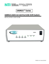
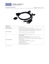
• HDUSBVEXT-xx-MM cable for each CPU being connected to the switch
Where:
xx is the length of the cable in feet (3,6,10, or 15 feet available)
MM indicates male-to-male connector
Cables can be purchased from Network Technologies Inc by calling 800-RGB-TECH (800-742-8324) or 330-562-7070
or by visiting our website at www.networktechinc.com
.
See page 46 for some of the available cables.
HD15 Male
High Density
USBType A Male
15HD-Male
USB Type A
Male
HDUSBVEXT-xx-MM
(3,6,10 and 15 foot cables available)
HD15 Male
Video
15HD-Male

NTI UNIMUX SINGLE-USER HIGH DENSITY VGA USB KVM SWITCH
3
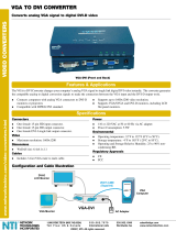
FEATURES AND FUNCTIONS
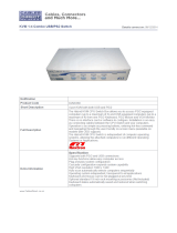
1. CPU Select Switches- push to manually switch to a specific CPU or change the switch operating mode
2. Mode Status LEDs- for visual indication of switch operating mode
3. IEC Power Connector- for attachment of power cord
4. Power switch- for turning the power to the UNIMUX On/Off
5. CPU x- 15HD yellow female high-density connectors- for connection of CPU cables for video and device support
6. USB User Device- USB Type A female connectors- for connection of user device cables;
7. USB User Device- for USB cable from touch screen monitor or CAC card reader (UNIMUX-USBV-xHDU models only)
8. MONITOR x- 15HD female connectors- for connection of user monitors
9. RS232- RJ45 female- for attaching RS232 interface cable from a CPU to control the functions of one or more switches
161514131211109
87654321
Scan
CommandBroadcast
UNIMUX
R
NTI
R
Network Technologies Inc
250V,2A
12 4
11 3 10 2
9 1
CPU CPU
16 8
15 7 14 6
13 5
CPU CPU
NETWORK TECHNOLOGIES INCORPORATED 1275 Danner Drive, Aurora Ohio 44202 330-562-7070 www.networktechinc.com
MONITOR
RS232
12
34 5 6 7
9
8

NTI UNIMUX SINGLE-USER HIGH DENSITY VGA USB KVM SWITCH
4
Additional Features
• Any USB type user device can control any USB CPU (Windows, MAC, and SUN platforms).
• Power cycle circuit control allows the UNIMUX switch to be powered OFF, then ON, at any time without affecting the attached
CPUs. (This assumes that the CPU supports hot plugging.)
• Security features can be enabled.
• A microprocessor is dedicated to each CPU, preventing connected CPUs from locking up.
• Any user device cable can be hot-plugged.
• The front panel LEDs indicate the CPU the user is connected to.
• No dip-switches or jumpers necessary to configure.
• Video formats up to 2048X1536 can be displayed from all platforms.
• Users can control the switch using the On Screen Display (OSD)
• RS232 control allows control of the switch with one CPU serial port. (Windows-based software is provided.)
• NTI Switch Control Program provides easy and powerful graphical control of NTI switches through the RS232 interface.
(Windows only.)

NTI UNIMUX SINGLE-USER HIGH DENSITY VGA USB KVM SWITCH
5
RACK MOUNTING INSTRUCTIONS
This NTI switch was designed to be mounted to a rack or to sit on a desktop. It includes rackmount ears to make attachment to a
rack easy, and rubber feet to be applied to the bottom of the case if it will instead sit on a flat surface. If this will sit on a flat
surface, simply apply the rubber feet to the bottom of the case in each of the 4 corners.
To Mount to a Rack
1. Attach the ears to the switch using the 6-32x3/16" flat Phillips-head screws (6) provided as shown in the illustration below.
The holes in the ears should line up with pre-threaded holes in the sides of the NTI switch. Tighten the screws securely.
Figure 1- Secure rackmount ears to switch
2. Install 4 captive nuts (not provided) to the rack in locations that line up with the holes in the mounting ear on the NTI switch.
3. Secure the NTI switch to the rack using four 3/16" diameter screws (not provided). Each screw should be of sufficient length
to go completely through the NTI mounting ear, rack frame and fully engage all threads in the captive nut. Be sure to
tighten all mounting screws securely.
4. Attach all cables securely to the switch and where necessary supply adequate means of strain relief for cables.
Figure 2- Secure switch to a rack
6-32x3/16"
Flat Head
Screws
(Provided)
Rackmount Ear
NTI Switch
Front of Switch
Captive Nuts
3/16" Diameter Screws
Rack
(not provided)
(not provided)
NTI Switch

NTI UNIMUX SINGLE-USER HIGH DENSITY VGA USB KVM SWITCH
6
INSTALLATION
It is not necessary to turn OFF power to CPUs or monitors during this installation unless RS232 is going to be connected. All
cables, except for the RS232 cables, may be hot plugged.
If using RS232 Control see RS232 section on page 31 for more information. Observe normal precautions when connecting the
RS232 cables to the CPU. Refer to the owner’s manual for the CPU being connected for precautions, if any.
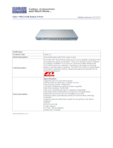
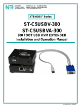
1. Connect the 15HD male cable end from the user monitor to the female black 15HD port marked “MONITOR x” on the rear of
the UNIMUX switch (see Figure 3 ). If a touch screen monitor is being connected (models with touch screen support only),
connect the USB cable from the monitor to any one of the USB type A connectors in the same user device port group (see Figure
4 ).
Figure 3- Install user monitor
Figure 4- Install user touch screen monitor
VGA
Multi-Scan
Monitor
Existing Cable
250V,2A
12 4 11 3
10 2
9 1
CPU CPU
16 8 15 7
14 6
13 5
CPU CPU
NETWORK TECHNOLOGIES INCORPORATED 1275 Danner Drive, Aurora Ohio 44202 330-562-7070 www.networktechinc.com
MONITOR
RS232
Rear View of UNIMUX-USBV-16HDU
15HD Male
Video Connector
15HD Female
Video Connector
VGA
Touch Screen
Monitor
Existing Cable
250V,2A
12 4 11 3
10 2
9 1
CPU CPU
16 8 15 7
14 6
13 5
CPU CPU
NETWORK TECHNOLOGIES INCORPORATED 1275 Danner Drive, Aurora Ohio 44202 330-562-7070 www.networktechinc.com
MONITOR
RS232
Rear View of UNIMUX-USBV-16HDU
USB Type A Male
15HD Male
Video Connector
15HD Female
Video Connector
Existing Cable

NTI UNIMUX SINGLE-USER HIGH DENSITY VGA USB KVM SWITCH
7
2. Connect the user devices to the USB type A female ports labeled with the USB symbol ( ) on the rear of the UNIMUX
switch (see Figure 5 ).
Note: If there are three (3) USB type A female ports present (models with CAC card reader or touch screen support only),
then the third USB port is available for connection of a USB cable from a touch screen type monitor or CAC card reader.
The USB ports are not device specific, so the mouse, keyboard, and touchscreen monitor or CAC card reader cable can
be connected to any of the available USB ports present.
Note: If device cables are not long enough to reach the UNIMUX switch, they can be extended either 5 or 10 meters
using either 1 or 2 NTI USB-A+A-5M Improved Active USB 5 Meter Extensions (see Figure 6)- purchased separately.
Contact your NTI salesperson for more details by calling (800) 742-8324 (800-RGB-TECH) or (330) 562-7070 or visit our
website at http://www.networktechinc.com
.
Note: Only one non-HID (Human Interface Device) can be connected to the UNIMUX at a time. (i.e. if a CAC card reader
is present, then a touch screen monitor cannot be used)
Figure 5- Install user devices (mouse and keyboard)
Figure 6- Use USB-A+A-5M to extend a device, or a computer
NTI
NETWORK
TECHNOLOG IES
INCORPORATED
Tel: 330-5 62-70 70
www. nti1.c om
1275 Danner Drive
Fax: 330-5 62-1 999
R
Aurora,Ohio 44202
USB-A+A-5M
USB
DEVICE
CPU
USB KEYBOARD
USB TYPE A
MALE CONNECTOR
USB TYPE A
FEMALE CONNECTOR
TO UNIMUX
SWITCH
USB Keyboard
USB
Mouse
USB Type A
Male Connectors
USB Type A Male
USB Type A Female
250V,2A
12 4 11 3
10 2
9 1
CPU CPU
16 8 15 7
14 6
13 5
CPU CPU
NETWORK TECHNOLOGIES INCORPORATED 1275 Danner Drive, Aurora Ohio 44202 330-562-7070 www.networktechinc.com
MONITOR
RS232
Rear View of UNIMUX-USBV-16HDU
CAC
Reader

NTI UNIMUX SINGLE-USER HIGH DENSITY VGA USB KVM SWITCH
8
3. For each CPU:
• Connect a USB type A cable end of a HDUSBVEXT-xx-MM cable to a USB type A female user device port on a CPU.
• Connect the 15HD blue male cable end of a HDUSBVEXT-xx-MM cable to the video port of the same CPU.
• Connect the 15HD yellow male cable end of the HDUSBVEXT-xx-MM cable to a yellow “CPU x” port on the UNIMUX
switch. (See Figure 7)
Figure 7- Connect each CPU using a HDUSBVEXT-xx-MM cable
4. Power-up
• The UNIMUX can be powered at any time.
• The CPUs can be powered at any time although if a CPU needs a keyboard and/or mouse at power-ON it should be powered
after connecting to and powering-ON the UNIMUX.
• USB input devices (keyboard and mouse) can be hot plugged to and from the UNIMUX at any time.
Note: The order in which the CPUs and switch are powered up does not matter. A power strip can be used.
250V,2A
12 4 11 3
10 2
9 1
CPU CPU
16 8 15 7
14 6
13 5
CPU CPU
NETWORK TECHNOLOGIES INCORPORATED 1275 Danner Drive, Aurora Ohio 44202 330-562-7070 www.networktechinc.com
MONITOR
RS232
Rear View of UNIMUX-USBV-16HDU
USB Type A Female
USB Type A Male
15HD Female
Video Connector
Rear View of Windows USB CPU
Video Port
Input Device Port
15HD High Density
(Yellow) FemaleConnector
HDUSBVEXT-xx-MM
(3,6,10 and 15 foot cables available)
15HD Male
Video Connector
15HD Male
Video Connector

NTI UNIMUX SINGLE-USER HIGH DENSITY VGA USB KVM SWITCH
9
Immediately after powering ON the UNIMUX, the following splash screen will appear on the monitor if the OSD option is built into
the switch:
If the security option is enabled (see page 12 for details on the
"Security Option"), when the UNIMUX is powered up the user will be
prompted for a username and password to continue. If the security
option is not enabled the monitor will display the desktop image for
the connected CPU and the user can continue with normal operation
of the connected CPU.
RS232 Connection
If RS232 control will be used, connect one end of the CAT5 patch cable (supplied) to the port labeled “RS232” on the rear of the
UNIMUX. Plug the other end of the CAT5 cable into either the RJ45-to-DB9 or RJ45-to-DB25 adapter supplied, and connect the
adapter to the RS232 port on the control terminal. Follow the instruction under “RS232 Control” on page 31 for configuration and
use of the RS232 control feature.
Figure 8- Connect cable for RS232 control
250V,2A
12 4 11 3
10 2
9 1
CPU CPU
16 8 15 7
14 6
13 5
CPU CPU
NETWORK TECHNOLOGIES INCORPORATED 1275 Danner Drive, Aurora Ohio 44202 330-562-7070 www.networktechinc.com
MONITOR
RS232
Rear View of UNIMUX-USBV-16HDU
VGA
Multi-Scan
Monitor
Control Terminal
RJ45-to-DB9 Adapter
(supplied)
CAT5 Patch Cable
(supplied)
RJ45-to-DB25 Adapter
(supplied)
or

NTI UNIMUX SINGLE-USER HIGH DENSITY VGA USB KVM SWITCH
10
Limitations
• Only one non-HID (Human Interface Device) can be connected at a time (device other than keyboard or mouse)
• A USB hub (single or multi-port) can be used provided only USB input devices are plugged into it.
• Only a USB Windows or SUN keyboard or USB mouse may be connected to the USB port on a USB MAC keyboard
• A maximum of 5 input devices may be connected to the UNIMUX either directly or through hubs.
See Fig. 7 for some examples of input device combinations that can be used with the UNIMUX.
Figure 9- Compatible device combinations
USB Windows Keyboard
USB
Mouse
USB Type A
Male Connectors
USB MAC Keyboard
USB
Mouse
USB
Mouse
USB
Mouse
USB Windows Keyboard
USB Windows Keyboard
USB MAC Keyboard
USB MAC Keyboard
2 USB hubs in series (Daisy-Chained)
Typical Installation- 1 Keyboard, 1 Mouse
Optional- Multiple keyboards and mice
Optional- MAC USB keyboard and mouse
USB
Hub

NTI UNIMUX SINGLE-USER HIGH DENSITY VGA USB KVM SWITCH
11
USING THE UNIMUX USB KVM SWITCH
Basic Operation
Once the UNIMUX is properly connected, the UNIMUX will enable a connection to be made between the CPUs attached to its
VIDEO and CPU ports and the monitor and input devices attached to the MONITOR and DEVICES ports. The LEDs on the
control panel of the UNIMUX will illuminate depending on which port (and corresponding CPU) is being connected to the monitor
and input devices.
The UNIMUX can be controlled by three methods:
• front panel control using touch-switches and LEDs
• OSD control via the user devices
• RS-232 control (see page 31)
Front Panel Control
There is a touch-switch and LED on the front panel of the UNIMUX for each CPU the switch will connect the monitor and
input devices to. Pressing any touch-switch on the front panel of the UNIMUX will connect the corresponding CPU to the monitor
and input devices.
Holding down any front panel touch-switch for more than 2 seconds will cause the UNIMUX to cycle through all modes of
operation including COMMAND, BROADCAST, SCAN, and NORMAL (described starting on page 17). The three MODE LEDs on
the front panel indicate which mode is selected. Release the touch-switch when the LEDs indicate the desired mode. When no
mode LEDs are illuminated the user is in Normal Mode controlling directly the CPU to which the user is connected through the
UNIMUX.
Keyboard Control
Keyboard control of the UNIMUX can be achieved using OSD Command Mode. Command Mode is operated using the keyboard
and mouse in conjunction with OSD menus superimposed onto the monitor. For all models use the menus as instructed on page
12.
By pressing <Ctrl> + < ` > (accent key), the user can enter Command Mode. Once in Command Mode, typing a series of
commands will cause the UNIMUX to connect the user to any one CPU connected to the switch. Pressing the <Esc> key will exit
Command Mode.

NTI UNIMUX SINGLE-USER HIGH DENSITY VGA USB KVM SWITCH
12
OSD CONTROL
OSD superimposes a menu system on the user’s video screen with a list of all connected CPUs. OSD allows CPUs to be named
(with up to 12 character names). OSD then allows selection of CPUs by that name. Connected CPUs can be listed by name or
by port number. OSD Search Mode enables the user to type in the first few characters of the CPU's name and the OSD will
locate it. HELP screens assist with all OSD functions.
Guidelines for Navigating OSD Menus
Throughout this manual, various rules apply to navigating the menus used to control and operate the UNIMUX.
• OSD menus can be navigated using the mouse, the arrows on the keyboard, hot keys (highlighted in red) and the
<Page Up>, <Page Down>, <Home>,<Tab> and <End> keys.
- The <up arrow> and <down arrow> moves the cursor up or down one line item at a time in a scrollable
window, or between menu items in a menu item list
- The <left arrow> and <right arrow> will move the cursor left or right through menu items or while in
editable fields (such as when editing port names)
- <Page Up> and <Page Down> increase/decrease the listed ports by one page at a time
- <Home> will jump to the beginning of the list
- <Tab> will jump between selectable fields, left to right
to move between menu items
- <Shift>+<Tab> will jump between selectable fields, right to left
- <End> will jump to the end of the list.
• Only alphabetic and numeric characters can be typed in the OSD menu fields
• Positioning the mouse cursor over a menu function or CPU name will highlight the background (green highlight for
menu functions, cyan or light blue for CPUs)
• The scroll bar can be used by clicking on the corresponding up and down arrow above and below the scroll bar.
• The mouse wheel may be used to move the selection bar
• The <Shift> key must be used to enter an uppercase letter within all OSD menus.
• Clicking on a listed CPU while in Command Mode will connect the user to that CPU.
• Available functions will have white characters with one red character. The red character corresponds to a keyboard
“hot key”. Hot keys are not case sensitive. Functions that are not available will be transparent.
• When changing characters for names, passwords, or values within an edit field, click on the field or select and press
<Enter> to enter the field for editing, and press <Enter> again to exit the edit field.
• To exit (and step back 1 menu) from any menu, press <Esc> on the keyboard .
• All screens that include “F1:Help” for context-sensitive help will also respond to pressing the <
F2> key to provide
“Global Help” screens with basic menu navigation help.
Security Option
The security option in the OSD Control of the UNIMUX USB KVM switch enables an administrator to control access to CPU ports
for each user. Up to 63 users can be created. These users have controlled access to any CPU. Only the administrator can
activate or deactivate the security features on the user port. Finally, the administrator can set a maximum idle time value after
which the current user will be logged out and the login screen displayed again if the user has no activity. The current security
status, idle time out, and scan dwell time are all saved and will be restored whenever power to the switch is cycled OFF, then ON.
To reset the administrator's password call NTI and have the device serial number of the UNIMUX available. For more on
security, see page 20.

NTI UNIMUX SINGLE-USER HIGH DENSITY VGA USB KVM SWITCH
13
Initial startup
When the UNIMUX is first powered ON, a splash screen similar to the following will appear:
Press any key and the UNIMUX will connect you to the first CPU port with a connected CPU that is powered ON.
To access Command Mode and connect to a different port or perform other user access functions (see below), press <Ctrl> +
<`> (accent/tilde key).
User Access Functions
Command Mode
In order to control the switch with the keyboard, Command Mode must be enabled. To enable Command Mode from the
keyboard:
Press
All the status lights on the keyboard will illuminate to indicate that Command Mode is enabled. At this point, the Command Mode
menu will be displayed.
The Command Mode menu (see Figure 10) lists all CPUs by name and port number. Only 8 ports are listed on the screen at a
time. To view the other portions of the list, scroll using the arrow keys on the keyboard or use the mouse to click on the arrows on
the scroll bar in the OSD menu. When the Command Mode main menu is displayed, the first displayed port in the list will be the
port the current user is connected to, followed by the next seven consecutively numbered ports. (Alternatively the list may be
sorted alphabetically- press the letter <O> to toggle sort method.) The names of accessible ports are displayed with blue
characters. If Security is activated, the access rights for the user logged-in may not include all ports. Names of restricted access
ports are displayed in black.
Note: In a cascaded system (see page 37), if a switch is connected to a port, all the names of the ports of the slave
switch will be displayed instead of the name of that port of the master switch. This rule applies recursively to all slave
switches. If one of the slave switches is powered-OFF during operation, the Status field in the ports name list will
display question marks. In this situation, the user should either power-ON the slave switch or send an Update
Configuration Command (<Ctrl> + <Tab>). If the slave switch is powered back ON without updating the configuration
and security is enabled, the text in the window for CPU type and power status will turn red until the configuration is
updated. (The red text indicates that the slave switch was logged out.)
`
Ctrl
~
(ACCENT/TILDE
KEY)
`
+

NTI UNIMUX SINGLE-USER HIGH DENSITY VGA USB KVM SWITCH
14
An arrow to the left of a port number in the list indicates
the port the user is currently connected to. From
left to right, the columns display the following:
• Port Number
• Port Name
• Power Status of the CPU (ON/OFF)
Note: “NAC” indicates a non-accessible computer
for that user
• The actual user number (1-8) connected to the CPU.
• If no user is connected to a CPU, the user number is
replaced by a "–" (dash).
Figure 10- Command Mode main menu-User
Note: While in Command Mode, the numbers on the NUM PAD on the keyboard are not active. If numbers are required
while in Command Mode, use the numbers on the main key bank.
The list below describes the command functions available from the keyboard within the OSD mode of control after entering into
Command Mode:
Function Keystroke
Select the previous port
up arrow
Select the next port
down arrow
Go to specific port- Press any valid number from 1-
1024 to connect to a desired port.
port # - Enter
Increases the ports listed by 1 page
Page Down
Decreases the ports listed by 1 page
Page Up
Enter “Settings” menu
T
Toggle ports listed to view by port number or
alphabetically by port name
O (letter, not
number)
Enable/disable Scan Mode
S
Enable/disable Broadcast Mode
B
Enter Administrator menu
(only available if the Administrator is logged in)
A
Select the first port on the switch
Home
Select the last port on the switch
End
Display Help menu
F1
Global Help- display window navigation tips used
throughout all menus
F2
Display port information- when pressed, a window
displays the port name and its position in the
configuration structure by level and port number
F3
Update configuration- use to update the information
describing the structure of the cascaded switches.
Use if a slave is powered-ON or OFF at any time after
initial startup
R or F5
Note: The user must exit
Command Mode to type to a CPU.
To exit Command Mode press
<Esc> on the keyboard.
Port Numbe
r
Power
Status
User
Scroll Bar
Curso
r
Port Name
Menu
Items
Selection
Bar

NTI UNIMUX SINGLE-USER HIGH DENSITY VGA USB KVM SWITCH
15
Function Keystroke
Enter Find Mode, add a character to search string
and select the CPU’s name that matches best.
Type any alphabetical or numeric character (A-Z, 0-9)
Note: use is not case sensitive
F
Switch to selected port
Enter
Logout (you will be prompted for confirmation)
L
Exit Command Mode
Esc
Figure 11- Administrator’s main menu
Settings
To enter the Settings menu (see Figure 12) press <T> from the Command Mode menu. The list below describes the Settings
menu functions available from the keyboard:
Function Keystroke
Open OSD Settings screen
O
Go to Broadcast list
B
Go to Scan list
S
Change the scan dwell time period
Enter any value from 002-255
(for more on this-see “Scan Mode”
page 17)
T
Enable/Disable right mouse button
click emulation with Apple 1-button
mouse (see “Mouse Click
Equivalents” on page 29 for more)
R
Exit from Settings menu
Return to Main menu
Esc
Figure 12- Settings menu
When the <T> is pressed, the current value of the scan dwell time is selected with an edit field (see Figure 12) . The user can
introduce a new value for scan dwell time and press <Enter> to save it or <Esc> to exit. Any value between 002 and 255
(seconds) is acceptable.
/