Page is loading ...

TECHNICAL MANUAL
INSTALLATION MANUAL FOR EXPORT UNITS
SERVICE MANUAL FOR DOMESTIC UNITS
FOR JACKSON MODELS:
TEMPSTAR GPX
TEMPSTAR HH GPX
Jackson MSC, INC.
P.O. BOX 1060
HWY. 25E
BARBOURVILLE, KY. 40906
FAX (606) 523-9196
PHONE (606) 523-9795
www.jacksonmsc.com
DUAL TEMPERATURE, GAS HEATED, DOOR-TYPE DISHMACHINES
August 6, 2007
P/N 7610-002-57-32 (Revision D)


i
REVISION/
PAGE
REVISION
DATE
MADE
BY
APPLICABLE
ECN
DETAILS
C 06-08-04 MAW 7006
Changed thermostat bracket from 17372 to 18164. Changed to
new layout.
D 07-24-06 MAW
7445, 7553
7571
Converted to centered layout. Replace 05700-002-63-16 with
04730-207-15-00 nipple. Add false panel assembly and wash
thermostat kits.
3 08-06-07 MAW PROCESS Corrected 110V amps from 14 to 24.

ii
NOMENCLATURE FOR THE MODELS COVERED IN THIS MANUAL
TEMPSTAR HH GPX
TEMPSTAR GPX = Gas heated, hot water sanitizing, door-type dishmachine
TEMPSTAR HH GPX = Gas heated, hot water sanitizing, door-type dishmachine with higher hood
Model:
Serial No.:
Installation Date:
Service Rep. Name:
Phone No.:

Section Description Page
I. SPECIFICATION INFORMATION
Specifications of the Tempstar GPX 2
Specifications of the Tempstar HH GPX 3
Dimensions for the Tempstar GPX 4
Dimensions for the Tempstar HH GPX 5
Table Dimensions 6
II. INSTALLATION/OPERATION INSTRUCTIONS
Installation Instructions 8
Electrical Installation Instructions 9
Gas Booster Heater Connection 10
Operation Instructions 12
III. PREVENTATIVE MAINTENANCE 15
IV. TROUBLESHOOTING 17
V. SERVICE PROCEDURES
Rinse Solenoid Valve Repair Parts Kit 20
Vacuum Breaker Repair Parts Kit 22
VI. PARTS
Control Box Assembly, Tempstar GPX 27
Control Box Assembly, Tempstar HH GPX 29
Hood Assembly, Tempstar GPX 31
Hood Assembly, Tempstar HH GPX 32
Frame Assemblies 33
Tub Assembly 34
Cantilever Arm/Door Assembly, Tempstar GPX 36
Cantilever Arm/Door Assembly, Tempstar HH GPX 38
Inlet Plumbing Assemblies 40
Rinse Header Plumbing Assembly 41
Recirculating Plumbing Assembly 42
1/2” Solenoid Valve/Vacuum Breaker Repair Kits 43
Wash & Rinse Assemblies, Tempstar GPX 44
Wash & Rinse Assemblies, Tempstar HH GPX 46
Steam Coil Assembly 48
Exhaust Fan Control Option/Safety Door Interlock Option 49
Tempstar GPX False Panel Installation 50
Tempstar HH GPX False Panel Installation 51
Drain Quench Option 52
VII. SCHEMATICS
115 Volt, 50/60 Hertz, Single Phase Tempstar GPX 54
208 - 230 Volt, 50/60 Hertz, Single & Three Phase Tempstar GPX 55
115 Volt, 50/60 Hertz, Single Phase Tempstar HH GPX 56
208 -230 Volt, 50/60 Hertz, Single & Three Phase Tempstar HH GPX 57
Exhaust Fan Control Option/Safety Door Interlock Option 58
TABLE OF CONTENTS
iii

1
SECTION 1:
SPECIFICATION INFORMATION

Tempstar/HH GPX Series Technical Manual 7610-002-57-32
Issued: 07-24-2006 Revised: N/A
SECTION 1: SPECIFICATION INFORMATION
SPECIFICATIONS OF THE TEMPSTAR GPX
2
PERFORMANCE/CAPABILITIES
OPERATING CAPACITY (RACKS/HOUR)
RACKS PER HOUR 57
DISHES PER HOUR 1425
GLASSES PER HOUR 1425
OPERATING CYCLE (SECONDS)
WASH TIME 45
RINSE TIME 11
DWELL TIME 2
TOTAL CYCLE TIME 60
TANK CAPACITY (GALLONS)
WASH TANK (MINIMUM) 8.0
WASH PUMP CAPACITY
GALLONS PER MINUTE 150
ELECTRICAL REQUIREMENTS
WASH PUMP MOTOR HP 3/4
RECIRCULATOR PUMP MOTOR HP 1/8
NOTE: Typical Electrical Circuit is based upon (1) 125% of the
full amperage load of the machine and (2) typical fixed-trip cir-
cuit breaker sizes as listed in the NEC 2002 Edition. Local
codes may require more stringent protection than what is dis-
played here. Always verify with your electrical service con-
tractor that your circuit protection is adequate and meets all
applicable national and local codes. These numbers are pro-
vided in this manual simply for reference and may change
without notice at any given time.
RINSE TYPICAL
HEATER TOTAL ELECTRICAL
VOLTS PH HZ RATINGS AMPS CIRCUIT
110 - 120 1 60 N/A 14 20 AMP
208 - 240 1 60 N/A 7 15 AMP
WATER REQUIREMENTS
INLET TEMPERATURE BOOSTER OUTPUT (BTU)
60 -110°F 100,000
110 -140°F 60,000
WASH TEMPERATURE (MINIMUM) 150°F
RINSE TEMPERATURE (MINIMUM) 180°F
GALLONS PER HOUR 52.2
WATER LINE SIZE I.P.S. (Minimum) 1/2”
DRAIN LINE SIZE I.P.S. (Minimum) 1-1/2”
FLOW PRESSURE P.S.I. 20A5
NOTE: Always refer to the machine data plate for specific
electrical and water requirements. The material provided on
this page is for reference only and may be subject to change
without notice.

Tempstar/HH GPX Series Technical Manual 7610-002-57-32
Issued: 07-24-2006 Revised: 08-06-2007
SECTION 1: SPECIFICATION INFORMATION
SPECIFICATIONS OF THE TEMPSTAR HH GPX
3
PERFORMANCE/CAPABILITIES
OPERATING CAPACITY (RACKS/HOUR)
RACKS PER HOUR 53
DISHES PER HOUR 1325
GLASSES PER HOUR 1325
OPERATING CYCLE (SECONDS)
SELECTION (A)
WASH TIME 45
RINSE TIME 15
TOTAL CYCLE TIME 60
SELECTION (B)
WASH TIME 103
RINSE TIME 15
DWELL TIME 2
TOTAL CYCLE TIME 120
SELECTION (C)
WASH TIME 163
RINSE TIME 15
DWELL TIME 2
TOTAL CYCLE TIME 180
SELECTION (D)
WASH TIME 283
RINSE TIME 15
DWELL TIME 2
TOTAL CYCLE TIME 300
TANK CAPACITY (GALLONS)
WASH TANK (MINIMUM) 8.0
WASH PUMP CAPACITY
GALLONS PER MINUTE 150
ELECTRICAL REQUIREMENTS
WASH PUMP MOTOR HP 2.0
RECIRCULATOR PUMP MOTOR HP 1/8
NOTE: Typical Electrical Circuit is based upon (1) 125% of the
full amperage load of the machine and (2) typical fixed-trip cir-
cuit breaker sizes as listed in the NEC 2002 Edition. Local
codes may require more stringent protection than what is dis-
played here. Always verify with your electrical service con-
tractor that your circuit protection is adequate and meets all
applicable national and local codes. These numbers are pro-
vided in this manual simply for reference and may change
without notice at any given time.
RINSE TYPICAL
HEATER TOTAL ELECTRICAL
VOLTS PH HZ RATINGS AMPS CIRCUIT
110 - 120 1 60 N/A 24 20 AMP
208 - 240 1 60 N/A 7 15 AMP
WATER REQUIREMENTS
INLET TEMPERATURE BOOSTER OUTPUT (BTU)
LESS THAN 60°F 200,000
60 -110°F 100,000
140°F 60,000
WASH TEMPERATURE (MINIMUM) 150°F
RINSE TEMPERATURE (MINIMUM) 180°F
GALLONS PER HOUR 72.0
WATER LINE SIZE I.P.S. (MINIMUM) 1/2”
DRAIN LINE SIZE I.P.S. (MINIMUM) 1-1/2”
FLOW PRESSURE P.S.I. 20A5
NOTE: Always refer to the machine data plate for specific
electrical and water requirements. The material provided on
this page is for reference only and may be subject to change
without notice.

Tempstar/HH GPX Series Technical Manual 7610-002-57-32
Issued: 07-24-2006 Revised: N/A
SECTION 1: SPECIFICATION INFORMATION
DIMENSIONS FOR TEMPSTAR GPX
A- DRAIN 1 1/2” NPT
B- WATER INLET 1/2” NPT
C - ELECTRICAL CONNECTION
D- STANDARD WALL CLEARANCE WITH DISHTABLE 4”
E- OUTLET TO BOOSTER HEATER 3/4” NPT
F- INLET FROM BOOSTER HEATER 3/4” NPT
LEGEND
1”
14"
14"
34”
TABLE
HEIGHT
17”
MACHINE
OPENING
64 3/8”
76”
W/ DOOR
OPEN
21”
11”
60 5/8”
ELECTRICAL
CONNECTION
TO THE
FLOOR
18 1/4”
5”
13 1/4”
4 1/4”
4 7/8”
32”
25 1/4”
A
B
F
F
E
C
D
D
D
C
ALL DIMENSIONS ARE +/- 1/2”
DUE TO ADJUSTABLE FEET.
4

Tempstar/HH GPX Series Technical Manual 7610-002-57-32
Issued: 07-24-2006 Revised: N/A
SECTION 1: SPECIFICATION INFORMATION
DIMENSIONS FOR TEMPSTAR HH GPX
5
LEGEND:
A- DRAIN 1 1/2” NPT
B- WATER INLET 1/2” NPT
C - ELECTRICAL CONNECTION
D- STANDARD WALL CLEARANCE WITH DISHTABLE 4”
E- OUTLET TO BOOSTER HEATER 3/4” N.P.T.
F- INLET FROM BOOSTER HEATER 3/4” N.P.T.
ALL DIMENSIONS ARE +/- 1/2” DUE TO ADJUSTABLE FEET.
1”
11”
34”
TABLE
HEIGHT
17”
MACHINE
OPENING
74 3/4”
86 1/4”
W/ DOOR
OPEN
19”
3”
12 1/4”
12 3/4”
16 1/4”
5”
7 1/4”
4 1/4”
32”
25 1/4”
A
C
B
F
F
E
D
D

Tempstar/HH GPX Series Technical Manual 7610-002-57-32
Issued: 07-24-2006 Revised: N/A
SECTION 1: SPECIFICATION INFORMATION
TABLE DIMENSIONS
6
TABLE DIMENSIONS
CORNER INSTALLATION
TABLE DIMENSIONS
CONNECTION TO DISHMACHINE
TABLE DIMENSIONS
STRAIGHT THROUGH INSTALLATION
20 1/2”
OPENING
2 1/2”
4” MINIMUM
2 1/2”
4” MINIMUM
20 1/2”
OPENING
25 1/4”
20 1/2”
3/4”
1 1/2” ROLL
4” MINIMUM
2 1/2”
20 1/2”
OPENING
25 1/4”
25 1/4”
25 1/4”

7
SECTION 2:
INSTALLATION/OPERATION
INSTRUCTIONS

Tempstar/HH GPX Series Technical Manual 7610-002-57-32
Issued: 07-24-2006 Revised: N/A
SECTION 2: INSTALLATION/OPERATION INSTRUCTIONS
INSTALLATION INSTRUCTIONS
8
VISUAL INSPECTION: Before installing the unit, check the container and machine for damage. A damaged container is an indi-
cator that there may be some damage to the machine. If there is damage to both the container and machine, do not throw away
the container. The dishmachine has been inspected and packed at the factory and is expected to arrive to you in new, undam-
aged condition. However, rough handling by carriers or others may result in there being damage to the unit while in transit. If
such a situation occurs, do not return the unit to Jackson; instead, contact the carrier and ask them to send a representative to
the site to inspect the damage to the unit and to complete an inspection report. You must contact the carrier within 48 hours of
receiving the machine. Also, contact the dealer through which you purchased the unit.
UNPACKING THE DISHMACHINE: Once the machine has been removed from the container, ensure that there are no miss-
ing parts from the machine. This may not be obvious at first. If it is discovered that an item is missing, contact Jackson imme-
diately to have the missing item shipped to you.
LEVEL THE DISHMACHINE: The dishmachine is designed to operate while being level. This is important to prevent any dam-
age to the machine during operation and to ensure the best results when washing ware. The unit comes with adjustable bullet
feet, which can be turned using a pair of channel locks or by hand if the unit can be raised safely. Ensure that the unit is level
from side to side and from front to back before making any connections.
PLUMBING THE DISHMACHINE: All plumbing connections must comply with all applicable local, state, and national plumb-
ing codes. The plumber is responsible for ensuring that the incoming water line is thoroughly flushed prior to connecting it to
any component of the dishmachine. It is necessary to remove all foreign debris from the water line that may potentially get
trapped in the valves or cause an obstruction. Any valves that are fouled as a result of foreign matter left in the water line, and
any expenses resulting from this fouling, are not the responsibility of the manufacturer.
CONNECTING THE DRAIN LINE: The drain for the Tempstar models covered in this manual are gravity discharge drains. All
piping from the 1-1/2” FNPT connection on the wash tank must be pitched (1/4” per foot) to the floor or sink drain. All piping
from the machine to the drain must be a minimum 1-1/2” NPT and shall not be reduced. There must also be an air gap between
the machine drain line and the floor sink or drain. If a grease trap is required by code, it should have a flow capacity of 5 gal-
lons per minute.
NOTE: This equipment is not recommend for use with deionized water or other aggressive fluids. Use of deion-
ized water or other aggressive fluids will result in corrosion and failure of materials and components. Use of
deionized water or other aggressive fluids will void the manufacturer's warranty.
WATER SUPPLY CONNECTION: Ensure that you have read the section entitled “PLUMBING THE DISHMACHINE” above
before proceeding. Install the water supply line (1/2” pipe size minimum) to the dishmachine line strainer using copper pipe. It
is recommended that a water shut-off valve be installed in the water line between the main supply and the machine to allow
access for service. The water supply line is to be capable of 25 PSI “flow” pressure at the recommended temperature indicat-
ed on the data plate. For the Tempstar GPX, the line should also have the capacity to supply 52.2 GPH @ 25 PSI “flow” pres-
sure.
For the Tempstar HH GPX, the line should also have the capacity to supply 72 GPH @ 25 PSI “flow” pressure.
In areas where the water pressure fluctuates or is greater than the recommended pressure, it is suggested that a water pres-
sure regulator be installed. The Tempstar models covered in this manual come with water pressure regulators as standard
equipment. Please notify Jackson immediately if this component is not present on your machine.
Do not confuse static pressure with flow pressure. Static pressure is the line pressure in a “no flow” condition (all valves and
services are closed). Flow pressure is the pressure in the fill line when the fill valve is opened during the cycle.
It is also recommended that a shock absorber (not supplied with the Tempstar models) be installed in the incoming water line.
This prevents line hammer (hydraulic shock), induced by the solenoid valve as it operates, from causing damage to the equip-
ment.
WATER CONNECTION TO THE GAS BOOSTER HEATER: Refer to page entitled “GAS BOOSTER HEATER CONNEC-
TIONS”.

Tempstar/HH GPX Series Technical Manual 7610-002-57-32
Issued: 07-24-2006 Revised: N/A
SECTION 2: INSTALLATION/OPERATION INSTRUCTIONS
INSTALLATION INSTRUCTIONS
9
GAS BOOSTER HEATER ELECTRICAL INSTALLATION: The gas booster heater must have a separate electric hookup than
that supplied to the dishmachine. Please refer to the manual supplied with your gas booster heater.
GAS CONNECTION TO THE BOOSTER HEATER: Please refer to the manual supplied with your gas booster heater.
VENTILATION OF THE GAS BOOSTER HEATER: Please refer to the manual supplied with your gas booster heater.
PLUMBING CHECK: Slowly turn on the water supply to the machine after the incoming fill line and the drain line have been
installed. Check for any leaks and repair as required. All leaks must be repaired prior to placing the machine in operation.
ELECTRICAL POWER CONNECTION: Electrical and grounding connections must comply with the applicable portions of the
National Electrical Code ANSI/NFPA 70 (latest edition) and/or other electrical codes.
Disconnect electrical power supply and place a tag at the disconnect switch to indicate that you are working on the circuit.
The dishmachine data plate is located on the right side and to the front of the machine. Refer to the data plate for machine
operating requirements, machine voltage, total amperage load and serial number.
To install the incoming power lines, remove the control box cover. Install 3/4” conduit into the pre-punched holes in the back of
the control box. Route power wires and connect to power block and grounding lug. Install the service wires (L1 and L2) to the
appropriate terminals as they are marked on the terminal block. Install the grounding wire into the lug provided. and tighten the
connections. It is recommended that “DE-OX” or another similar anti-oxidation agent be used on all power connections.
VOLTAGE CHECK: Ensure that the power switch is in the OFF position and apply power to the dishmachine. Check the incom-
ing power at the terminal block and ensure it corresponds to the voltage listed on the data plate. If not, contact a qualified serv-
ice agency to examine the problem. Do not run the dishmachine if the voltage is too high or too low. Shut off the service break-
er and mark it as being for the dishmachine. Advise all proper personnel of any problems and of the location of the service
breaker. Replace the control box cover and tighten down the screws.

Tempstar/HH GPX Series Technical Manual 7610-002-57-32
Issued: 07-24-2006 Revised: N/A
SECTION 2: INSTALLATION/OPERATION INSTRUCTIONS
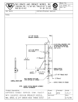
GAS BOOSTER HEATER CONNECTIONS
10
Due to the fact that each customer may have different requirements for the orientation of the gas booster heater relative to the
main dishmachine, the hose lengths that connect the two units must be customized during each installation.
To prevent incorrect measurements of the hose, it is recommended to place one barbed hose fitting into the end of the uncut
length of hose coil and attach that fitting to an appropriate connection. Run the hose to the corresponding connection on the
other unit before cutting the hose. Use a barbed hose fitting that is screwed into the second connection on the other unit before
cutting the hose. Use a barbed hose fitting that is screwed onto the second connection to gauge the correct distance. Ensure
a smooth “flow” of hose without any sharp turns or kinks.
To aid in pushing the barbed hose fitting into the hose, place the fitting on a hard surface (i.e. the floor) with the barbed end of
the fitting pointing upward and push the hose down onto the fitting. A small amount of lubricant (i.e. petroleum jelly) may aid in
this process.
Barbed Hose Fitting
Connection
Attach the hose fitting to
this connection before
making the cut at the
other end of the hose.
Hose
Cut the hose at the location where
the hose is even with the yellow
plastic stop.
ENSURE THAT THERE IS NO ELECTRICAL POWER APPLIED TO THE MACHINE WHEN MAKING GAS CONNECTION.
CHECK ALL GAS CONNECTIONS FOR LEAKS PRIOR TO APPLYING POWER.
THE GASES USED FOR COMBUSTION IN THIS DISH MACHINE ARE HIGHLY FLAMMABLE.
DO NOT SMOKE AROUND THIS MACHINE.
ENSURE THAT THE AREA WHERE THIS MACHINE IS TO BE INSTALLED IS WELL-VENTILATED TO PREVENT THE
BUILD-UP OF COMBUSTIBLE GASES.
ENSURE THAT ALL LOCAL HEALTH, FIRE, AND BUILDING CODES ARE BEING ADHERED TO WHEN INSTALLING
THIS MACHINE. VERIFY WITH LOCAL OFFICIALS IF THERE ARE ANY QUESTIONS.
INSTALL A SHUT-OFF VALVE AT THE GAS SOURCE.
WARNING

Tempstar/HH GPX Series Technical Manual 7610-002-57-32
Issued: 07-24-2006 Revised: N/A
SECTION 2: INSTALLATION/OPERATION INSTRUCTIONS
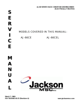
GAS BOOSTER HEATER CONNECTIONS (CONTINUED)
11
THERMAL
EXPANSION
TANK
RINSE
SOLENOID
VALVE
RECIRC
PUMP
GAS BOOSTER
HEATER
PHOSPHATE
WATER
TREATMENT
CARTRIDGE
Y-STRAINER
TEMPERATURE/PRESSURE
GAGE
HEATING COIL
VACUUM
BREAKER
PRESSURE
GAGE
PRESSURE
REGULATING
VALVE
RINSE ARM
INLET OUTLET
3/4" HOSE
3/4" HOSE
TEMPERATURE/PRESSURE
GAGE
S
ALL COMPONENTS WITHIN THE DOTTED REGION
ARE FOUND WITHIN THE FOOTPRINT OF THE MACHINE.
ALL OTHER ITEMS ARE INSTALLED AT THE SITE.
BUILDINGS
WATER
SUPPLY
DISHMACHINE
*
*
*
*
*
PRESSURE
RELIEF
VALVE
*
AN ASTERISK ( )
DENOTES ITEMS
INCLUDED WITH
THE GAS BOOSTER
HEATER
DRAIN VALVE

Tempstar/HH GPX Series Technical Manual 7610-002-57-32
Issued: 07-24-2006 Revised: N/A
SECTION 2: INSTALLATION/OPERATION INSTRUCTIONS
OPERATION INSTRUCTIONS
12
PREPARATION: Before proceeding with the start-up of the unit, verify the following:
1. The pan strainer and pump suction strainer are in place and are clean.
2. The overflow tube and o-ring are installed.
3. That the wash and rinse arms are screwed securely into place and that their endcaps are tight. The wash and rinse arms
should rotate freely.
GAS BOOSTER HEATER OPERATION: For all start up and operation information, please refer to the manual supplied with
your gas booster heater.
POWER UP: To energize the unit, turn on the power at the service breaker. The voltage should have been previously verified
as being correct. If not, the voltage will have to be verified.
FILLING THE WASH TUB (TEMPSTAR GPX): Ensure that the delime switch is in the NORMAL position, and place the power
switch into the ON position. The Tempstar model should fill automatically and shut off when the appropriate level is reached
(just below the pan strainer). Verify that the drain stopper is preventing the wash tub water from leaking excessively. There may
be some slight leakage from the drain hole. Verify that there are no other leaks on the unit before proceeding any further. The
wash tub must be completely filled before operating the wash pump to prevent damage to the component. Once the wash tub
is filled, the unit is ready for operation.
FILLING THE WASH TUB (TEMPSTAR HH GPX): For the initial fill, ensure that the cycle selection switch is in the “AUTO”
(automatic) position, and place the power switch in the “ON” position. The unit will fill automatically and run through a rinse
cycle. Open the doors and verify that the water level is correct. Hereafter, the water level is controlled by the overflow tube.
Verify that the drain stopper is preventing the wash tub water from draining excessively. There may be some slight leakage from
the drain hole. Verify that there are no other leaks on the unit before proceeding any further. The wash tub must be complete-
ly filled before operating the wash pump to prevent damage to the component. Once the wash tub is filled, the unit is ready for
operation.
WARE PREPARATION: Proper preparation of ware will help ensure good results and less re-washes. If not done properly, ware
may not come out clean and the efficiency of the dishmachine will be reduced. It is important to remember that a dishmachine
is not a garbage disposal and that simply throwing unscraped dishes into the machine simply defeats the purpose altogether
of washing the ware. Scraps should be removed from ware prior to being loaded into a rack. Pre-rinsing and pre-soaking are
good ideas, especially for silverware and casserole dishes. Place cups and glasses upside down in racks so that they do not
hold water during the cycle. The dishmachine is meant not only to clean, but to sanitize as well, to destroy all of the bacteria
that could be harmful to human beings. In order to do this, ware must be properly prepared prior to being placed in the machine.
DAILY MACHINE PREPARATION: Refer to the section entitled “PREPARATION” at the top of this page and follow the instruc-
tions there. Afterwards, check that all of the chemical levels are correct and/or that there is plenty of detergent available for the
expected workload.
WARM-UP CYCLES: For a typical daily start-up, it may be necessary to run the machine through 3 cycles to ensure that all of
the cold water is out of the system and to verify that the unit is operating correctly. To cycle the machine, ensure that the power
is on and that the tub has filled to the correct level. Lift the doors and the cycle light will illuminate. When the light goes out,
close the doors, the unit will start, run through the cycle, and shut off automatically. Repeat this two more times. The unit should
now be ready to proceed with the washing of ware.
WASHING A RACK OF WARE: To wash a rack, open the doors completely (being careful for hot water that may drip from the
doors) and slide the rack into the unit. Close the doors and the unit will start automatically. Once the cycle is completed, open
the door (again watching for the dripping hot water) and remove the rack of clean ware. Replace with a rack of soiled ware and
close the doors. The process will then repeat itself.

Tempstar/HH GPX Series Technical Manual 7610-002-57-32
Issued: 07-24-2006 Revised: N/A
SECTION 2: INSTALLATION/OPERATION INSTRUCTIONS
OPERATION INSTRUCTIONS (CONTINUED)
13
OPERATIONAL INSPECTION: Based upon usage, the pan strainer may become clogged with soil and debris as the workday
progresses. Operators should regularly inspect the pan strainer to ensure it has not become clogged. If the strainer does, it will
reduce the washing capability of the machine. Instruct operators to clean out the pan strainer at regular intervals or as required
by work load.
SHUTDOWN AND CLEANING: At the end of the workday, close the doors. When the unit completes the cycle, turn the power
switch to the OFF position and open the doors. Remove and clean the pan strainer. Remove the drain stopper from the tub and
allow the tub to drain (NOTE: the wash tank water will be hot so caution is advised). Once the wash tub is drained, remove the
pump suction strainer. Remove soil and debris from the strainer and set to the side. Unscrew the wash and rinse arms from
their manifolds. Remove the endcaps and flush the arms with water. Use a brush to clean out the inside of the arms. If the noz-
zles appear to be clogged, use a toothpick to remove the obstruction. Wipe the inside of the unit out, removing all soil and
scraps. Reassemble the wash and rinse arms and replace them in the unit. The arms only need to be hand tight, do not use
tools to tighten them down. Reinstall the drain stopper
and strainers and close the doors.
WATER CONSUMPTION ISSUES AND EFFICIENCY: The Tempstar HH GPX provides you, the customer, with the ability to
control the hourly rack capacity of the machine. Extending the wash cycle to wash severely soiled ware, such as mixing bowls,
does not increase the machine’s water consumption. However, selecting a longer time cycle does lower the amount of dishes
the machine will be able to wash per hour. It is important for operators to select the correct wash cycle depending on the amount
of washing required. Not every rack of dishes requires the machine to be set on the longest wash cycle!
Using good prescrapping procedures and observing the results of individual racks of ware, operators will soon gain the expe-
rience and knowledge required to ensure that the Tempstar HH GPX operates at peak efficiency for your needs.
Water hardness and detergent usage will also effect the results of the Tempstar HH GPX. This manual provides a page enti-
tled “Detergent Control” for your reference. It is recommended that owners and operators take the time to carefully review this
section in order to ensure that everything is done to make sure the Tempstar HH GPX operates at peak performance!

14
SECTION 3:
PREVENTATIVE MAINTENANCE

Tempstar/HH GPX Series Technical Manual 7610-002-57-32
Issued: 07-24-2006 Revised: N/A
SECTION 3: PREVENTATIVE MAINTENANCE
PREVENTATIVE MAINTENANCE
15
The dishmachines covered in this manual are designed to operate with a minimum of interaction with the operator. However,
this does not mean that some items will not wear out in time. Jackson highly recommends that any maintenance and repairs
not specifically discussed in this manual should be performed by QUALIFIED SERVICE PERSONNEL ONLY. Performing main-
tenance on your dishmachine may void your warranty if it is still in effect, so if you have a question or concern, do not hesitate
to contact one of the QUALIFIED SERVICE AGENCIES listed in the back of this manual.
There are many things that operators can do to prevent catastrophic damage to the dishmachine. One of the major causes of
component failure has to do with prescrapping procedures. A dishmachine is not a garbage disposal; any large pieces of mate-
rial that are put into the machine shall remain in the machine until they are either broken up (after spreading out on your ware!)
or physically removed. Strainers are installed to help catch debris, but they do no good of they are clogged. Have operators
regularly inspect the pan strainers to ensure (1) that they are free of soil and debris and (2) they are laying flat in the tub.
When cleaning out strainers, do NOT beat them on waste cans. The strainers are made of metal and can be forgiving; but once
severe damage is done, it is next to impossible for the strainer to work in the way it was designed to. Wipe out strainers with
a rag and rinse under a faucet if necessary. For stubborn debris, a toothpick should be able to dislodge any obstructions from
the perforations. Always ensure that strainers are placed back in the machine before operation and that they lay flat in the tub.
You may wish to also refer to the page entitled “Detergent Control” in order to learn more about how your water hardness will
effect the performance of your machine. Hard water makes dishmachines work harder and decreases efficiency.
Again, it is important to remind operators that trying to perform corrective maintenance on the dishmachine could lead to larg-
er problems or even cause harm to the operator. If a problem is discovered; secure the dishmachine using proper shut down
procedures as listed in this manual and contact a QUALIFIED SERVICE AGENCY as listed in the back of this manual.
Some problems, however, may having nothing to do with the machine itself and no amount of preventative maintanence is
going to help. A common problem has to do with temperatures being too low. Verify that the water temperatures coming to your
dishmachine match the requirements listed on the machine data plate. There can be a variety of reasons why your water tem-
perature could be too low and you should discuss it with a QUALIFIED SERVICE AGENCY to determine what can be done.
By following the operating and cleaning instructions in this manual, you should get the most efficient results from your machine.
As a reminder, here are some steps to take to ensure that you are using the dishmachine the way it was designed to work:
1. Ensure that the water temperatures match those listed on the machine data plate.
2. Ensure that all strainers are in place before operating the machine.
3. Ensure that all wash and/or rinse arms are secure in the machine before operating.
4. Ensure that drains are closed/sealed before operating.
5. Remove as much soil from dishes by hand as possible before loading into racks.
6. Do not overfill racks.
7. Ensure that glasses are placed upside down in the rack.
8. Ensure that all chemicals being injected to machine have been verified as being at the correct concentrations.
9. Clean out the machine at the end of every workday as per the instructions in the manual.
10. Always contact a QUALIFIED SERVICE AGENCY whenever a serious problem arises.
11. Follow all safety procedures, whether listed in this manual or put forth by local, state or national codes/regulations.
/