
DCH 300
Operating instructions en
Mode d’emploi fr
Manual de instrucciones es
Manual de instruções pt

1
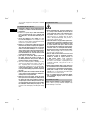
This Product is Certified
Ce produit est homologué
Producto homologado por
Este produto está registrado
CUS

2
3

2
1
3
"#
"“
"]
"[
"Ç
4

5

DCH 300 Diamond cutter
It is essential that the operating instructions
are read before the machine is operated for
the first time.
Always keep these operating instructions
together with the machine.
Ensure that the operating instructions are
with the machine when it is given to other
persons.
Contents Page
1. General information 1
2. Description 2
3. Accessories, consumables 5
4. Technical data 5
5. Safety instructions 6
6. Before use 11
7. Operation 13
8. Care and maintenance 15
9. Troubleshooting 15
10. Disposal 16
11. Manufacturer’s warranty 17
1 These numbers refer to the corresponding illustra-
tions. The illustrations can be found on the fold‐out
cover pages. Keep these pages open while studying
the operating instructions.
In these operating instructions, the designation “the
power tool” always refers to the DCH 300 diamond
cutter.
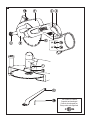
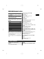
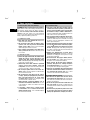
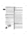
Operating controls and indicators 1
@
Spindle lockbutton
;
Front grip
=
On / off switch
%
Switch‐on interlock release button
&
Diamond cutting disc
(
Spindle
)
Guard (hood)
+
Guide wheels
§
Clamping nut wrench, 24 mm AF / 10 mm AF
/
Hex. socket wrench, 6 mm AF
:
Guard (hood) clamping screw
·
Dust removal connector cap
$
Service indicator
£
Theft protection indicator (option)
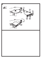
DCH 300 mounting system for diamond cutting
discs 2
|
Reversible flange 60 mm dia.
¡
Clamping flange, 60 mm dia.
Q
Clamping nut, M16 x 1.5
DCH 300 mounting system for synthetic resin‐
bonded fiber‐reinforced abrasive cutting discs (op-
tional) 3
W
Reversible flange 80 mm dia.
E
Synthetic resin‐bonded fiber‐reinforced cutting
discs with a diameter of 300 mm (12")
R
Clamping flange, 80 mm dia.
T
Clamping nut, M16 x 1.5
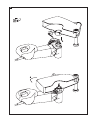
Hood extension with depth gauge (optional) 4
Z
Hood extension
U
Hook
I
Stop
O
Cutting depth sliding indicator
P
Cutting depth scale
1. General information
1.1 Safety notices and their meaning
DANGER
Draws attention to imminent danger that could lead
to serious bodily injury or fatality.
WARNING
Draws attention to a potentially dangerous situation
that could lead to serious personal injury or fatality.
en
1

CAUTION
Draws attention to a potentially dangerous situation
that could lead to slight personal injury or damage to
the equipment or other property.
NOTE
Draws attention to an instruction or other useful
information.
1.2 Explanation of the pictograms and other
information
Warning signs
General
warning
Warning:
electricity
Obligation signs
Wear a hard
hat.
Wear eye
protection.
Wear ear
protection.
Wear
protective
gloves.
Wear safety
shoes.
Wear
breathing
protection.
Symbols
Read the
operating
instructions
before use.
Return waste
material for
recycling.
Amps Volts
Alternating
current
Revolutions
per minute
Diameter Nominal speed
under no load
Double
insulated
Location of identification data on the machine
The type designation and serial number can be found
on the type identification plate on the machine. Make
a note of this data in your operating instructions and
always refer to it when making an enquiry to your
Hilti representative or service department.
Type:
Serial no.:
2. Description
2.1 Use of the product as directed
The DCH 300 is an electrically powered diamond cutter for professional use in the construction industry.
It is designed for cutting mineral materials with diamond discs without use of water.
A vacuum cleaner with the appropriate filter, e.g. Hilti VCD 50 vacuum cleaner, must be used when cutting
mineral materials.
In order to avoid electrostatic effects, a vacuum cleaner equipped with an antistatic hose should be used.
Use only diamond cutting discs with a maximum permissible peripheral speed of at least 80 m/sec (16000
ft/min).
The power tool is to be used exclusively in pushing mode (counter rotation).
The use of liquids, e.g. to cool the disc or suppress dust, is not permissible.
Do not use the power tool for cutting with cutting tools of a type not specified in these operating instructions
(e.g. circular saw blades) or for grinding.
When equipped with synthetic resin‐bonded fiber‐reinforced abrasive cutting discs, the power tool can also
be used for cutting metals. When doing so, use only synthetic resin‐bonded fiber‐reinforced abrasive cutting
discs with a maximum permissible peripheral speed of at least 80 m/sec (16000 ft/min).
en
2

The working environment may be as follows: construction site, workshop, renovation, conversion or new
construction.
To avoid the risk of injury, use only genuine Hilti accessories and cutting tools.
Observe the safety rules and operating instructions for the accessories used.
Observe the information printed in the operating instructions concerning operation, care and maintenance.
The machine is designed for professional use and may be operated, serviced and maintained only by trained,
authorized personnel. This personnel must be informed of any special hazards that may be encountered. The
machine and its ancillary equipment may present hazards when used incorrectly by untrained personnel or
when used not as directed.
The machine may be used only in a dry environment.
The machine may be operated only when connected to a power supply providing a voltage and frequency in
compliance with the information given on its type identification plate.
Do not use the machine where there is a risk of fire or explosion.
Working on materials hazardous to the health (e.g. asbestos) is not permissible.
Modification of the machine or tampering with its parts is not permissible.
2.2 Switches
On/off switch with switch‐on interlock
2.3 Starting current limitation
The starting current drawn by the power tool is several times higher than its rated current. The electronic
starting current limiter reduces the starting current drawn by the power tool and thus prevents the mains fuse
blowing. It also allows the power tool to start smoothly, without a jolt.
2.4 Restart interlock
The power tool does not restart by itself after an interruption in the electric supply. The switch must first be
released and then pressed again after approx. 1 second.
2.5 TPS theft protection system (optional)
The power tool may be optionally equipped with the TPS theft protection system. If equipped with this feature,
the power tool can be unlocked and made ready for operation only through use of the corresponding TPS key.
2.6 LED indicators
Service indicator LED (see section “Care and maintenance”)
Theft protection system indicator (optional) (see section “Operation”)
2.7 Guard (hood) with guide wheels
Cutting and slitting work on stone may be carried out only when the power tool is equipped with a dust hood
with wheels.
2.8 Electronic overload protection
The electronic overload protection system monitors current input and thus protects the power tool from
overload.
If the motor is overloaded through application of excessive working pressure, the power tool’s performance
drops noticeably or it may come to a complete standstill. A standstill should be avoided.
Permissible overload cannot be given as a specific value as it depends on the temperature of the motor.
If the power tool has been overloaded, release the pressure applied and then allow it to run under no load for
approx. 30 seconds.
en
3

2.9 Using extension cords
Use only extension cords of a type approved for the application and with conductors of adequate gauge. The
power tool may otherwise lose performance and the extension cord may overheat. Check the extension cord
for damage at regular intervals. Replace damaged extension cords.
Recommended minimum conductor gauge (cross section) and max. cable lengths
Conductor cross section 14 AWG 12 AWG
Mains voltage 110‐120 V
‐
125 ft
Do not use extension cords with 16 AWG conductor cross section.
2.10 Using extension cords outdoors
When working outdoors, use only extension cords that are approved and correspondingly marked for this
application.
2.11 Using a generator or transformer
This tool may be powered by a generator or transformer when the following conditions are fulfilled: The unit
must provide a power output in watts of at least twice the value printed on the type identification plate on
the power tool. The operating voltage must remain within +5% and ‐15% of the rated voltage at all times,
frequency must be in the 50 – 60 Hz range and never above 65 Hz, and the unit must be equipped with
automatic voltage regulation and starting boost.
Never operate other power tools or appliances from the generator or transformer at the same time. Where
applicable, use a generator or transformer designed for simultaneous power tool and vacuum cleaner operation.
Switching other power tools or appliances on and off may cause undervoltage and / or overvoltage peaks,
resulting in damage to the power tool.
2.12 Hood extension with depth gauge (optional)
The power tool can be fitted with an optional hood extension with depth gauge. This improves dust removal
performance for cutting mineral materials. The maximum cutting depth can be set with the aid of the cutting
depth scale on the hood extension.
2.13 The items supplied as standard include:
1 Power tool with DCH‑EX 300 hood
1 Reversible flange 60 mm dia.
1 Clamping flange, 60 mm dia.
1 Clamping nut, M16 x 1.5
1 Clamping nut wrench, 24 mm AF / 10 mm
AF
1 Hex. socket wrench, 6 mm AF
1 Cardboard box
1 Operating instructions
2.14 Cutting disc specifications
Diamond cutting discs in compliance with the requirements of ANSI B7.1 are to be used with the power tool.
Synthetic resin‐bonded fiber‐reinforced cutting discs in compliance with ANSI B7.1 (cutting‐off wheels of
the straight, not offset type) may also be used with this power tool for working on metals. In this case, the
appropriate DCH 300 ABR disc mount (see accessories) must be used with the power tool.
The mounting instructions issued by the disc manufacturer must also be observed.
en
4

3. Accessories, consumables
DCH 300 ABR disc mount 212259, Reversible flange
Ø80 mm, clamping flange
Ø80 mm, clamping nut M16 x 1.5
Depth gauge for the DCH 300
212131
Vacuum cleaner
VCD 50
Antistatic hose, complete
Length 5 m (16.4 ft), Ø36
Hilti toolbox
DCH 300
Disc type Specification Material
Diamond cutting disc
DCH‑D 12" C1 Concrete
Diamond cutting disc
DCH‑D 12" C2
Hard concrete
Diamond cutting disc
DCH‑D 12" M1
Masonry, sand‐lime block
Diamond cutting disc
DCH‑D 12" C10 Concrete (Economy Line
disc)
Diamond cutting disc
DCH‑D 12" M10
Masonry (Economy Line
disc)
4. Technical data
Right of technical changes reserved.
Other information about the power tool DCH 300
Rated voltage 120 V
Rated current input 20 A
Mains frequency
60 Hz
Dimensions 705 mm (27.76 in) x 240 mm (9.45 in) x 235 mm
(9.25 in)
Drive spindle thread M 16 X 1.5
Disc arbor size 25.4 mm (1")
Cutting disc
Ø Max. 305 mm (12")
Cutting disc thickness
Max. 3.5 mm (¹⁄₈")
Weight of the power tool
9.4 kg (20.72 lb)
Protection class Protection class I (grounded) or protection class II
(double insulated). See type identification plate.
Rated speed under no load Max. 4,900/min
Clamping nut tightening torque M16 x 1.5: 40…50 Nm (30…37 lb/ft)
en
5

5. Safety instructions
5.1 General power tool safety warnings
WARNING! Read all safety warnings and all instruc-
tions. Failure to follow the warnings and instructions
may result in electric shock, fire and/or serious in-
jury. Save all warnings and instructions for future
reference. The term “power tool” in the warnings
refers to your mains‐operated (corded) power tool or
battery‐operated (cordless) power tool.
5.1.1 Work area safety
a) Keep work area clean and well lit. Cluttered or
dark areas invite accidents.
b) Do not operate power tools in explosive atmo-
spheres, such as in the presence of flammable
liquids, gases or dust. Power tools create sparks
which may ignite the dust or fumes.
c) Keep children and bystanders away while oper-
ating a power tool. Distractions can cause you to
lose control.
5.1.2 Electrical safety
a) Power tool plugs must match the outlet. Never
modify the plug in any way. Do not use any
adapter plugs with earthed (grounded) power
tools. Unmodified plugs and matching outlets will
reduce risk of electric shock.
b) Avoid body contact with earthed or grounded
surfaces, such as pipes, radiators, ranges and
refrigerators. There is an increased risk of electric
shock if your body is earthed or grounded.
c) Do not expose power tools to rain or wet con-
ditions. Water entering a power tool will increase
the risk of electric shock.
d) Do not abuse the cord. Never use the cord for
carrying, pulling or unplugging the power tool.
Keep cord away from heat, oil, sharp edges
or moving parts. Damaged or entangled cords
increase the risk of electric shock.
e) When operating a power tool outdoors, use an
extension cord suitable for outdoor use. Use of a
cord suitable for outdoor use reduces the risk of
electric shock.
f) If operating a power tool in a damp location
is unavoidable, use a residual current device
(RCD) protected supply. Use of an RCD reduces
the risk of electric shock.
5.1.3 Personal safety
a) Stay alert, watch what you are doing and use
common sense when operating a power tool. Do
not use a power tool while you are tired or under
the influence of drugs, alcohol or medication. A
moment of inattention while operating power tools
may result in serious personal injury.
b) Use personal protective equipment. Always wear
eye protection. Protective equipment such as dust
mask, non‐skid safety shoes, hard hat, or hearing
protection used for appropriate conditions will
reduce personal injuries.
c) Prevent unintentional starting. Ensure the switch
is in the off‐position before connecting to power
source and/or battery pack, picking up or carrying
the tool. Carrying power tools with your finger on
the switch or energising power tools that have the
switch on invites accidents.
d) Remove any adjusting key or wrench before
turning the power tool on. A wrench or a key left
attached to a rotating part of the power tool may
result in personal injury.
e)
Do not overreach. Keep proper footing and bal-
ance at all times. This enables better control of
the power tool in unexpected situations.
f) Dress properly. Do not wear loose clothing or
jewellery. Keep your hair, clothing and gloves
away from moving parts. Loose clothes, jewellery
or long hair can be caught in moving parts.
g) If devices are provided for the connection of dust
extraction and collection facilities, ensure these
are connected and properly used. Use of dust
collection can reduce dust ‐related hazards.
5.1.4 Power tool use and care
a) Do not force the power tool. Use the correct
power tool for your application. The correct power
tool will do the job better and safer at the rate for
which it was designed.
b) Do not use the power tool if the switch does not
turn it on and off. Any power tool that cannot be
controlled with the switch is dangerous and must
be repaired.
c) Disconnect the plug from the power source and/
or the battery pack from the power tool before
making any adjustments, changing accessories,
en
6

or storing power tools. Such preventive safety
measures reduce the risk of starting the power
tool accidentally.
d) Store idle power tools out of the reach of children
and do not allow persons unfamiliar with the
power tool or these instructions to operate the
power tool. Power tools are dangerous in the
hands of untrained users.
e) Maintain power tools. Check for misalignment or
binding of moving parts, breakage of parts and
any other condition that may affect the power
tool’s operation. If damaged, have the power
tool repaired before use. Many accidents are
caused by poorly maintained power tools.
f) Keep cutting tools sharp and clean. Properly
maintained cutting tools with sharp cutting edges
are less likely to bind and are easier to control.
g) Use the power tool, accessories and tool bits etc.
in accordance with these instructions, taking into
account the working conditions and the work to be
performed. Use of the power tool for operations
different from those intended could result in a
hazardous situation.
5.1.5 Service
a) Have your power tool serviced by a qualified
repair person using only identical replacement
parts. This will ensure that the safety of the power
tool is maintained.
5.2 Safety instructions for all operations
5.2.1 Safety warnings for abrasive cutting‐off
operations
a) This power tool is intended to function as a
cut‐off tool. Read all safety warnings, instruc-
tions, illustrations and specifications provided
with this power tool. Failure to follow all instruc-
tions listed below may result in electric shock, fire
and/or serious injury.
b) Operations such as grinding, sanding, wire
brushing or polishing are not recommended to
be performed with this power tool. Operations for
which the power tool was not designed may create
a hazard and cause personal injury.
c) Do not use accessories which are not specif-
ically designed and recommended by the tool
manufacturer. Just because the accessory can be
attached to your power tool, it does not assure
safe operation.
d) The rated speed of the accessory must be at
least equal to the maximum speed marked on
the power tool. Accessories running faster than
their rated speed can break and fly apart.
e) The outside diameter and the thickness of your
accessory must be within the capacity rating
of your power tool. Incorrectly sized accessories
cannot be adequately guarded or controlled.
f) The arbour size of wheels, flanges, backing
pads or any other accessory must properly fit the
spindle of the power tool. Accessories with arbour
holes that do not match the mounting hardware
of the power tool will run out of balance, vibrate
excessively and may cause loss of control.
g) Do not use a damaged accessory. Before each
use inspect the accessory such as abrasive
wheels for chips and cracks, wire brush for
loose or cracked wires. If power tool or acces-
sory is dropped, inspect for damage or install
an undamaged accessory. After inspecting and
installing an accessory, position yourself and
bystanders away from the plane of the rotating
accessory and run the power tool at maximum
no‐load speed for one minute. Damaged acces-
sories will normally break apart during this test
time.
h) Wear personal protective equipment. Depending
on application, use face shield, safety goggles or
safety glasses. As appropriate, wear dust mask,
hearing protectors, gloves and workshop apron
capable of stopping small abrasive or workpiece
fragments. The eye protection must be capable
of stopping flying debris generated by various
operations. The dust mask or respirator must be
capable of filtrating particles generated by your
operation. Prolonged exposure to high intensity
noise may cause hearing loss.
i) Keep bystanders a safe distance away from
work area. Anyone entering the work area must
wear personal protective equipment. Fragments
of workpiece or of a broken accessory may fly
away and cause injury beyond immediate area of
operation.
j) Hold power tool by insulated gripping surfaces
only, when performing an operation where the
cutting accessory may contact hidden wiring or
its own cord. Cutting accessory contacting a “live”
wire may make exposed metal parts of the power
tool “live” and shock the operator.
en
7

k) Position the cord clear of the spinning accessory.
If you lose control, the cord may be cut or snagged
and your hand or arm may be pulled into the
spinning accessory.
l) Never lay the power tool down until the acces-
sory has come to a complete stop. The spinning
accessory may grab the surface and pull the power
tool out of your control.
m)Do not run the power tool while carrying it at
your side. Accidental contact with the spinning
accessory could snag your clothing, pulling the
accessory into your body.
n) Regularly clean the power tool’s air vents. The
motor’s fan will draw the dust inside the housing
and excessive accumulation of powdered metal
may cause electrical hazards.
o) Do not operate the power tool near flammable
materials. Sparks could ignite these materials.
p) Do not use accessories that require liquid
coolants. Using water or other liquid coolants
may result in electrocution or shock.
5.2.2 Further safety instructions for all
operations
Kickback and related warnings
Kickback is a sudden reaction to a pinched or snagged
rotating wheel. Pinching or snagging causes rapid
stalling of the rotating accessory which in turn causes
the uncontrolled power tool to be forced in the direc-
tion opposite of the accessory’s rotation at the point
of the binding.
For example, if an abrasive wheel is snagged or
pinched by the workpiece, the edge of the wheel that
is entering into the pinch point can dig into the surface
of the material causing the wheel to climb out or kick
out. The wheel may either jump toward or away from
the operator, depending on direction of the wheel’s
movement at the point of pinching. Abrasive wheels
may also break under these conditions.
Kickback is the result of power tool misuse and/or
incorrect operating procedures or conditions and can
be avoided by taking proper precautions as given
below.
a) Maintain a firm grip on the power tool and
position your body and arm to allow you to resist
kickback forces. Always use auxiliary handle,
if provided, for maximum control over kickback
or torque reaction during start‐up. The operator
can control torque reactions or kickback forces, if
proper precautions are taken.
b) Never place your hand near the rotating acces-
sory. Accessory may kickback over your hand.
c) Do not position your body in the area where
power tool will move if kickback occurs. Kickback
will propel the tool in direction opposite to the
wheel’s movement at the point of snagging.
d) Use special care when working corners, sharp
edges, etc. Avoid bouncing and snagging the
accessory. Corners, sharp edges or bouncing
have a tendency to snag the rotating accessory
and cause loss of control or kickback.
e) Do not attach a saw chain woodcarving blade or
toothed saw blade. Such blades create frequent
kickback and loss of control.
5.2.3 Safety warnings specific for abrasive
cutting‐off operations
a) Use only wheel types that are recommended for
your power tool and the specific guard designed
for the selected wheel. Wheels for which the
power tool was not designed cannot be adequately
guarded and are unsafe.
b) The guard must be securely attached to the power
tool and positioned for maximum safety, so the
least amount of wheel is exposed towards the
operator. The guard helps to protect operator from
broken wheel fragments and accidental contact
with wheel.
c) Wheels must be used only for recommended
applications. For example: do not grind with
the side of cut‐
off wheel. Abrasive cut‐off wheels
are intended for peripheral grinding, side forces
applied to these wheels may cause them to shatter.
d) Always use undamaged wheel flanges that are of
correct size and shape for your selected wheel.
Proper wheel flanges support the wheel thus re-
ducing the possibility of wheel breakage. Flanges
for cut‐off wheels may be different from grinding
wheel flanges.
e) Do not use worn down wheels from larger power
tools. Wheel intended for larger power tool is not
suitable for the higher speed of a smaller tool and
may burst.
5.2.4 Additional safety warnings specific for
abrasive cutting‐off operations
a) Do not “jam” the cut‐off wheel or apply excessive
pressure. Do not attempt to make an excessive
depth of cut. Overstressing the wheel increases the
loading and susceptibility to twisting or binding of
en
8

the wheel in the cut and the possibility of kickback
or wheel breakage.
b) Do not position your body in line with and behind
the rotating wheel. When the wheel, at the point
of operation, is moving away from your body, the
possible kickback may propel the spinning wheel
and the power tool directly at you.
c) When wheel is binding or when interrupting a
cut for any reason, switch off the power tool
and hold the power tool motionless until the
wheel comes to a complete stop. Never attempt
to remove the cut‐off wheel from the cut while
the wheel is in motion otherwise kickback may
occur. Investigate and take corrective action to
eliminate the cause of wheel binding.
d) Do not restart the cutting operation in the work-
piece. Let the wheel reach full speed and care-
fully reenter the cut. The wheel may bind, walk
up or kickback if the power tool is restarted in the
workpiece.
e) Support panels or any oversized workpiece to
minimize the risk of wheel pinching and kick-
back. Large workpieces tend to sag under their
own weight. Supports must be placed under the
workpiece near the line of cut and near the edge of
the workpiece on both sides of the wheel.
f) Use extra caution when making a “pocket cut”
into existing walls or other blind areas. The
protruding wheel may cut gas or water pipes,
electrical wiring or objects that can cause kickback.
5.3 Safety instruction for all operations
5.3.1 Safety instructions for all operations
a) Do not use wheels that require liquid coolants.
Using water or other liquid coolants may result in
electrocution or shock.
b) Use only wheel types that are recommended for
your power tool and the specific guard designed
for the selected wheel. Wheels for which the
power tool was not designed cannot be adequately
guarded and are unsafe.
5.3.2 Personal safety
a) Always hold the machine securely with both
hands on the grips provided. Keep the grips dry,
clean and free from oil and grease.
b) Breathing protection must be worn if the power
tool is used without a dust extraction system for
work that creates dust. Close the cap over the
dust removal connector.
c) Improve the blood circulation in your fingers by
relaxing your hands and exercising your fingers
during breaks between working.
d) Avoid touching rotating parts. Switch the power
tool on only after bringing it into position at
the workpiece. Touching rotating parts, especially
rotating drill bits, discs or blades, etc. may lead to
injury.
e) Always lead the supply cord and extension cord
away from the power tool to the rear while
working. This helps to avoid tripping over the cord
while working.
f) The guard must always be fitted when the power
tool is used for cutting metals. Close the cap
over the dust removal connector.
g) If the work involves breaking right through, take
the appropriate safety measures at the opposite
side. Parts breaking away could fall out and / or
fall down and injure other persons.
h) Children must be instructed not to play with the
appliance.
i) The appliance is not intended for use by chil-
dren, by debilitated persons or those who have
received no instruction or training.
j) Do not use the power tool if it starts with a jolt.
This may be an indication that the electronic control
unit is defective. Have the power tool repaired by
Hilti Service immediately.
k) WARNING: Some dust created by grinding, sand-
ing, cutting and drilling contains chemicals
known to cause cancer, birth defects, infertility
or other reproductive harm; or serious and per-
manent respiratory or other injury. Some exam-
ples of these chemicals are: lead from lead‐based
paints, crystalline silica from bricks, concrete and
other masonry products and natural stone, arsenic
and chromium from chemically‐treated lumber.
Your risk from these exposures varies, depending
on how often you do this type of work. To reduce
exposure to these chemicals, the operator and
bystanders should work in a well‐ventilated area,
work with approved safety equipment, such as
respiratory protection appropriate for the type of
dust generated, and designed to filter out mi-
croscopic particles and direct dust away from
the face and body. Avoid prolonged contact with
dust. Wear protective clothing and wash ex-
posed areas with soap and water. Allowing dust
to get into your mouth, nose, eyes, or to remain
en
9

on your skin may promote absorption of harmful
chemicals.
5.3.3 Power tool use and care
a) Cutting discs must be stored, handled and fitted
carefully in accordance with the manufacturer’s
instructions.
b) If use of a spacer ring or other intermediate
part is specified and the part is supplied with
the cutting disc, check to ensure that the part is
fitted.
c) Secure the workpiece. Use clamps or a vice
to secure the workpiece. The workpiece is thus
held more securely than by hand and both hands
remain free to operate the machine.
d) Before use, check that the cutting disc has been
fitted correctly and the clamping nut tightened.
Then allow the power tool to run for 30 seconds
under no load while holding it in a secure po-
sition. Switch off the power tool immediately if
significant vibration or any other faults are no-
ticed. Should this occur, check the entire system
in order to determine the cause.
e) Take steps to ensure that flying sparks from
the power tool do not present a hazard, i.e.
by striking yourself or other persons. Adjust the
position of the disc guard accordingly.
f) Slits cut in loadbearing walls of buildings or other
structures may influence the statics of the struc-
ture, especially when steel reinforcing bars or
load‐bearing components are cut through. Con-
sult the structural engineer, architect, or person
in charge of the building project before beginning
the work.
g) Guide the power tool carefully and make straight
cuts in order to avoid jamming the cutting disc.
Cutting curves is not permissible.
h) Guide the power tool evenly and do not apply
lateral pressure to the cutting disc. Always bring
the power tool into contact with the workpiece
at right angles. Do not attempt to alter the line
of cut by applying lateral pressure or by bending
the cutting disc while cutting is in progress. This
presents a risk of damaging or breaking the cutting
disc.
5.3.4 Electrical safety
a) Before beginning work, check the working area
(e.g. using a metal detector) to ensure that no
concealed electric cables or gas and water pipes
are present. External metal parts of the machine
may become live, for example, when an electric
cable is damaged accidentally. This presents a
serious risk of electric shock.
b) Check the machine’s supply cord at regular inter-
vals and have it replaced by a qualified specialist
if found to be damaged. Check extension cords
at regular intervals and replace them if found
to be damaged. Do not touch the supply cord or
extension cord if it is damaged while working.
Disconnect the supply cord plug from the power
outlet. Damaged supply cords or extension cords
present a risk of electric shock.
c) Dirty or dusty machines which have been used
frequently for work on conductive materials
should be checked at regular intervals at
a Hilti Service Center. Under unfavorable
circumstances, dampness or dust adhering to
the surface of the machine, especially dust from
conductive materials, may present a risk of
electric shock.
d) When working outdoors with a power tool check
to ensure that the tool is connected to the electric
supply by way of a ground fault circuit interrupter
(GFCI) with a rating of max. 30 mA (tripping
current). Use of a ground fault circuit interrupter
reduces the risk of electric shock.
e) Use of a ground fault circuit interrupter (GFCI)
with a maximum tripping current of 30 mA is
recommended.
5.3.5 Work area safety
Ensure that the workplace is well ventilated. Ex-
posure to dust at a poorly ventilated workplace may
result in damage to the health.
en
10

5.3.6 Personal protective equipment
The user and any other persons in the vicinity must
wear ANSI Z87.1‐approved eye protection, a hard
hat, ear protection, protective gloves and breathing
protection while the machine is in use.
6. Before use
WARNING
The supply cord must be disconnected from the
electric supply and the cutting disc or drive spindle
must have come to a complete stop before attempt-
ing to change or adjust discs, parts of the tool or its
accessories.
CAUTION
The mains voltage must comply with the specifica-
tion given on the type identification plate. Ensure
that the power tool is disconnected from the electric
supply.
CAUTION
Wear protective gloves, especially when changing
discs, adjusting the guard (hood) and when fitting
the hood extension with depth gauge.
6.1 Guard (hood)
WARNING
Never use the power tool without the guard (hood).
NOTE
If the guard (hood) clamping force is found to be
inadequate, this can be increased by tightening the
clamping screw slightly.
6.1.1 Fitting and adjusting the guard (hood) 5
1. Disconnect the supply cord plug from the power
outlet.
2. Use the hex. socket wrench to release the clamp-
ing screw.
3. Fit the guard (hood) onto the collar on the gearing
section.
4. Rotate the guard (hood) into the desired position.
5. Use the hex. socket wrench to tighten the clamp-
ing screw.
6.1.2 Removing the guard (hood)
1. Disconnect the supply cord plug from the power
outlet.
2. Use the hex. socket wrench to release the clamp-
ing screw.
3. Rotate the guard (hood) and pull it away from the
tool.
6.2 Depth gauge (optional)
DANGER
The hood extension with depth gauge is to be
used exclusively for cutting mineral materials with
diamond discs.
6.2.1 Fitting / removing the hood extension with
depth gauge 4
1. Disconnect the supply cord plug from the power
outlet.
2. Fit the hook over the guide wheel axle.
3. Pivot the hood extension into the hood until the
catch is heard to engage.
4. To remove the hood extension, press the catch
and pivot the hood extension down and away
from the hood.
6.2.2 Using the depth gauge to adjust cutting
depth
1. Press the cutting depth sliding indicator.
en
11

G
G
2. Move the cutting depth sliding indicator to the
desired cutting depth.
6.3 Fitting a cutting disc
DANGER
Use only the metric‐size clamping flange and the
wrench supplied with the power tool.
CAUTION
Use only cutting tools with a rated maximum per-
missible speed which is at least as high as the
machine’s highest no‐load running speed.
CAUTION
Cutting discs which are damaged or out of round
(causing vibration) must not be used.
CAUTION
Do not use synthetic resin‐bonded fiber‐reinforced
cutting discs that have exceeded their use‐by date.
NOTE
Diamond cutting discs in compliance with the re-
quirements of ANSI B7.1 are to be used with the
power tool. Synthetic resin‐bonded fiber‐reinforced
cutting discs in compliance with ANSI B7.1 (cut-
ting‐off wheels of the straight, not offset type) may
also be used with this power tool for working on
metals. In this case, the appropriate DCH 300 ABR
disc mount (see accessories) must be used with the
power tool. The mounting instructions issued by the
disc manufacturer must also be observed.
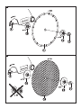
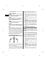
6.3.1 Fitting diamond cutting discs
The width of the slot G between the segments must
not exceed 10 mm (³⁄₈"). The thickness of the disc
must not exceed 3.5 mm (¹⁄₈").
The 60 mm dia. interchangeable flange can be used
on one side for cutting discs with an inner diameter
of 22.2 mm (⁷⁄₈") or, on the other side, with cutting
discs with an inner diameter of 25.4 mm (1"). Check
which side of the flange fits the arbor hole in the
cutting disc. The flange must center the disc.
1. Disconnect the supply cord plug from the power
outlet.
2. Clean the clamping flange and the clamping nut.
3. Fit the 60 mm diameter reversible flange onto the
spindle the right way round, so that it is no longer
free to rotate.
4. Place the diamond cutting disc on the reversible
flange.
5. Fit the 60 mm diameter clamping flange and the
clamping nut.
6. CAUTION Do not press the spindle lockbutton
before the drive spindle has stopped rotating.
Press the spindle lockbutton and hold it in this
position.
7. Use the wrench to tighten the clamping nut se-
curely and then release the spindle lockbutton.
8. Check to ensure that the spindle lockbutton has
disengaged.
6.3.2 Fitting synthetic resin‐bonded fiber‐
reinforced abrasive cutting discs (optional)
CAUTION
Never use flanges with a diameter of less than
80 mm with synthetic resin‐bonded fiber‐reinforced
cutting discs.
The 80 mm dia. interchangeable flange can be used
on one side for cutting discs with an inner diameter
of 22.2 mm (⁷⁄₈") or, on the other side, with cutting
discs with an inner diameter of 25.4 mm (1"). Check
which side of the flange fits the arbor hole in the
cutting disc. The flange must center the disc.
1. Disconnect the supply cord plug from the power
outlet.
2. Clean the clamping flange and the clamping nut.
3. Fit the 80 mm diameter reversible flange onto the
spindle the right way round, so that it is no longer
free to rotate.
4. Place the diamond cutting disc on the reversible
flange.
5. Fit the 80 mm diameter clamping flange and the
clamping nut.
6. CAUTION Do not press the spindle lockbutton
before the drive spindle has stopped rotating.
Press the spindle lockbutton and hold it in this
position.
7. Use the wrench to tighten the clamping nut se-
curely and then release the spindle lockbutton.
en
12

8. Check to ensure that the spindle lockbutton has
disengaged.
6.4 Removing the cutting disc from the tool
To remove the cutting disc from the tool, follow the
instructions for fitting the disc but carry out the steps
in the reverse order.
6.5 Storing and transporting cutting discs
CAUTION
Remove the cutting disc from the power tool after
use. The cutting disc may suffer damage if the power
tool is transported with the disc fitted.
CAUTION
Store the cutting disc in accordance with the man-
ufacturer’s recommendations. Incorrect or careless
storage may damage the cutting disc.
7. Operation
Hold tool by insulated gripping surfaces when per-
forming an operation where the cutting tool may
contact hidden wiring or its own cord. Contact with
a “live” wire will make exposed metal parts of the tool
“live” and shock the operator.
WARNING
Do not use the power tool if it starts with a jolt.
This may be an indication that the electronic control
unit is defective. Have the power tool repaired by Hilti
Service immediately.
CAUTION
The power tool and the cutting operation generate
noise. Wear ear protectors. Exposure to noise can
cause hearing loss.
CAUTION
The cutting operation may cause dangerous splinters.
Splintering material presents a risk of injury to the
eyes and body. Wear eye protection and a hard hat.
CAUTION
The direction of advance is important. The power
tool must always be advanced with the guide wheels
ahead and in contact with the material being cut.
There is otherwise a risk of kick‐back.
WARNING
The electric supply voltage must comply with the
information given on the type identification plate
on the power tool.
CAUTION
The cutting disc and parts of the power tool may
get hot through use. There is a risk of burning your
hands. Wear protective gloves. Touch the power
tool only at the grips provided.
CAUTION
Use clamps or a vice to hold the workpiece securely.
WARNING
Slits cut in loadbearing walls of buildings or other
structures may influence the statics of the structure,
especially when steel reinforcing bars or load‐bearing
components are cut through. Consult the structural
engineer, architect, or person in charge of the
building project before beginning the work.
7.1 Working with the power tool
Take care to ensure that the closed side of the guard
is always positioned toward the operator’s body.
Adjust the position of the guard (hood) to suit each
cutting application.
7.2 TPS theft protection system (optional)
NOTE
The power tool may be equipped with the optional
theft protection system. If the power tool is equipped
with this feature, it can be unlocked and made ready
for operation only with the corresponding TPS key.
en
13

7.2.1 Unlocking the power tool
1. Plug the supply cord into the power outlet. The
yellow theft protection indicator LED blinks. The
power tool is then ready to receive the signal from
the TPS key.
2. Hold the TPS key against the lock symbol. The
power tool is unlocked as soon as the yellow theft
protection indicator LED no longer lights.
NOTE If, for example, the electric supply is briefly
interrupted due to a power failure or disconnected
when moving to a different workplace, the power
tool remains ready for operation for approx. 20
minutes. In the event of a longer interruption, the
TPS key must be used again to unlock the power
tool.
7.2.2 Activation of the tool’s theft protection
system
NOTE
Further detailed information on activation and use
of the theft protection system can be found in the
operating instructions for the theft protection system.
7.3 Switching on
1. Plug the supply cord into the power outlet.
2. Always hold the tool securely with both hands on
the grips provided.
3. Unlock the on / off switch by pressing the
switch‐on interlock release button.
4. Press the on / off switch.
5. Reposition your thumb around the rear grip.
7.4 Switching off
Release the on / off switch.
The tool stops after the on / off switch is released.
The switch‐on interlock is re‐activated.
7.5 Working with cutting discs
DANGER
To reduce the risk of kick‐back, avoid bringing the
cutting tool into contact with the material in the
area indicated.
DANGER
Wherever possible, bring the wheels into contact
with the workpiece before starting the cut. Take
extra care in situations where this is not possible
or where the cutting disc is inserted in an existing
cut.
1. When cutting mineral materials, first bring the
tool’s guide wheels into contact with the object to
be cut.
2. Allow the power tool to reach full speed.
3. Apply pressure to the power tool so that the
cutting disc is pressed into the material slowly.
This ensures that particles and sparks generated
by the cutting operation are caught by the hood
and extracted by the dust removal system.
NOTE Apply moderate pressure, adjusting the
rate of advance to suit the material being cut.
NOTE The diamond disc may overheat and suffer
damage when cutting very hard mineral materials,
e.g. concrete with a high hard pebble content. A
trail of sparks right round the circumference of
the diamond cutting disc is a sure indication of
this. Should this occur, stop cutting and cool the
disc by allowing the tool to run under no load.
A drop in the rate of cutting progress can be an in-
dication of “blunt” (polished) diamond segments.
The segments can be resharpened by making a
few cuts in an abrasive material (Hilti sharpening
plate or sand‐lime block).
7.6 Using a suitable vacuum cleaner for working
on mineral materials
NOTE
Please read the operating instructions for the vacuum
cleaner for information about disposal of the material
collected.
Dust can be kept to a minimum when working by
using a suitable vacuum cleaner (such as the Hilti
VCD 50). Use of a vacuum cleaner also helps to cool
the segments on the disc and thus reduces segment
wear. In order to avoid electrostatic effects, a vacuum
cleaner equipped with an antistatic hose should be
used.
en
14

8. Care and maintenance
CAUTION
Disconnect the supply cord plug from the power
outlet.
8.1 Care of the power tool
DANGER
When working on metal under extreme conditions,
conductive dust may accumulate inside the power
tool. This may negatively affect the power tool’s
protective insulation. Under such conditions, the
tool should be plugged into a ground fault circuit
interrupter (GFCI) and use of a stationary dust
removal system and frequent cleaning of the tool’s
cooling air slots is recommended.
The outer casing of the motor and the grips are made
from impact‐resistant plastic. Parts of the grips have
a synthetic rubber covering.
Never operate the power tool when the ventilation
slots are blocked. Clean the ventilation slots carefully
using a dry brush. Do not permit foreign objects to
enter the interior of the power tool. Clean the outside
of the power tool at regular intervals with a slightly
damp cloth. Do not use a spray, steam pressure
cleaning equipment or running water for cleaning.
This may negatively affect the electrical safety of the
power tool. Always keep the grip surfaces of the
power tool free from oil and grease. Do not use
cleaning agents which contain silicone.
8.2 Service indicator
NOTE
The power tool is equipped with a service indicator.
LED indicators
Constant red light End of service interval ‐ servicing is due. After the
lamp lights for the first time, the power tool may
continue to be used for several hours (switched‐on
running time) before the automatic cut‐out is
activated. To ensure that the power tool is always
ready for use, it should be returned to Hilti for
servicing in good time.
Blinking red light
See section “Troubleshooting”.
8.3 Maintenance
WARNING
Repairs to the electrical section of the machine may
be carried out only by trained electrical specialists.
Check all external parts of the power tool for damage
at regular intervals and check that all controls operate
faultlessly. Do not operate the power tool if parts
are damaged or when the controls do not function
faultlessly. If necessary, the power tool should be
repaired by Hilti Service.
8.4 Checking the power tool after care and
maintenance
After carrying out care and maintenance, check that
all protective and safety devices are fitted and that
they function faultlessly.
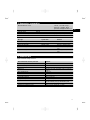
9. Troubleshooting
Fault Possible cause Remedy
The power tool doesn’t start.
Interruption in the electric supply. Plug in another electric appliance
and check whether it works.
The supply cord or plug is defective.
Have checked by a trained electrical
specialist and replaced if necessary.
en
15
Page is loading ...
Page is loading ...
Page is loading ...
Page is loading ...
-
 1
1
-
 2
2
-
 3
3
-
 4
4
-
 5
5
-
 6
6
-
 7
7
-
 8
8
-
 9
9
-
 10
10
-
 11
11
-
 12
12
-
 13
13
-
 14
14
-
 15
15
-
 16
16
-
 17
17
-
 18
18
-
 19
19
-
 20
20
-
 21
21
-
 22
22
-
 23
23
-
 24
24


Ask a question and I''ll find the answer in the document
Finding information in a document is now easier with AI
Related papers
-
Hilti AG 230-20D Operating instructions
-
Hilti 2075614 User manual
-
-
Hilti DCH 300 Operating instructions
-
Hilti 3490198 User guide
-
-
-
Hilti DCH 150SL User manual
-
Hilti 2257601 User guide
-