Sea gull lighting 15082B-965 Installation guide
- Category
- Household fans
- Type
- Installation guide
This manual is also suitable for

1590-CUL-ENG
HC-807
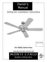
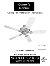
Owner’s
Manual
Ceiling Fan Installation Instructions
For 1590 Series Fans
READ AND SAVE THESE INSTRUCTIONS
Total fan weight
with light kit

1590-CUL-ENG
HC-807
Installation work and electrical wiring must be done by qualified person(s) in accordance with applicable codes and standards
(ANSI/NFPA 70-1996), including fire-rated construction.
Use this unit only in the manner intended by the manufacturer. If you have any questions contact the manufacturer.
After making the wire connections, the wires should be spread apart with the grounded conductor and the equipment-grounding con-
ductor on one side of the outlet box and ungrounded conductor on the other side of the outlet box.
Before you begin installing the fan, Switch power off at Service panel and lock service disconnecting means to prevent power from being
switched on accidentally. When the service disconnecting means cannot be locked, securely fasten a prominent warning device, such
as a tag, to the service panel.
Be cautious! read all instructions and safety information before installing your new fan. Review the accompanying assembly diagrams.
When cutting or drilling into wall or ceiling, do not damage electrical wiring and other hidden utilities.
Make sure the installation site you choose allows the fan blades to rotate without any obstructions. Allow a minimum clearance of 7 feet
from the floor to the trailing edge of the blade.
To reduce the risk of fire, electric shock, or personal injury, mount to outlet box or supporting system acceptable for fan support.
(Mounting must support at least 35 lbs.)
Do not bend blade holders during installation to motor, balancing or during cleaning. Do not insert foreign object between rotating
blades.
Attach the mounting bracket using only the hardware supplied with the outlet box.
To reduce the risk of fire or electric shock, do not use this fan with any solid state fan speed control device, or variable speed control.
If this unit is to be installed over a tub or shower, it must be marked as appropriate for the application.
NEVER place a switch where it can be reached from a tub or shower.
The combustion airflow needed for safe operation of fuel-burning equipment may be affected by this unit’s operation. Follow the heating
equipment manufacturer’s guideline safety standards such as those published by the National Fire Protection Association (NFPA), and
the American Society for Heating, Refrigeration and Air Conditioning Engineers (ASHRAE) and the local code authorities.
Before servicing or cleaning unit, Switch power off at Service panel and lock service disconnecting means to prevent power from being
switched on accidentally. When the service disconnecting means cannot be locked, securely fasten a prominent warning device, such
as a tag, to the service panel.
1.
2.
3.
4.
5.
6.
7.
8.
9.
10.
11.
12.
13.
14.
15.
Installation
WARNING: TO REDUCE THE RISK OF FIRE, ELECTRIC SHOCK, OR INJURY TO PERSONS,
OBSERVE THE FOLLOWING: READ AND SAVE THESE INSTRUCTIONS
SAFETY TIPS
TOOLS REQUIRED
Phillips Screwdriver Wire Cutters Pliers Step Ladder
Before you begin installing the fan, Switch power off
at Service panel and lock service disconnecting means
to prevent power from being switched on accidentally.
When the service disconnecting means cannot be
locked, securely fasten a prominent warning device,
such as a tag, to the service panel.
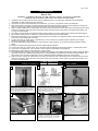
Before installing this fan make sure the outlet
box is properly installed to the house structure.
To reduce the risk of fire, electric shock, or per-
sonal injury, mount to outlet box or supporting
system acceptable for fan support.
(Mounting must support at least 35 lbs.)
Install the Mountiing Bracket to the Outlet box.
Use only the screws provided with the out-
let box.
Install canopy over the downrod.
3
2
1
4
Thread wire through downrod with canopy
assembled. Insert downrod into motor yoke.
Next, insert clevis pin through yoke and down-
rod and secure with cotter pin. (see insert)
5
6
Tighten both yoke set screws to further secure
downrod.

1590-CUL-ENG
HC-807
Carefully lift fan assembly onto mounting
bracket. Rotate fan so that the notch on the
ball engages the ridge in the mounting bracket.
This will allow hands-free wiring.
7
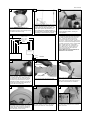
Attach blade brackets and floating brackets
onto blades.
12
Make wire connections to power source using
wire nuts provided. Make sure that no filiments
are outside of the wirenut. After making the
wire connections, the wires should be spread
apart with the grounded conductor and the
equipment-grounding conductor on one side of
the outlet box and ungrounded conductor on
the other side of the outlet box.
11
Raise the canopy up and align the two holes in
the canopy with the two holes in the hanger
bracket. Secure with two screws provided.
15
Attach blade bracket and floating bracket to
blade using screws and washers provided.
Tighen screws securely. Repeat this process 4
more times until all blades are assembled.
13
floating brackets
blade brackets
Install remote receiver by sliding into opening in
the Mounting bracket. Make sure that the dip
switches on the Transmitter and the Receiver
are set to the same position. See Fig for
remote operation
9
Check the motor for shipping stabilizers and
remove them if they are present. The screws,
washers and motor pads are pre-installed to
the blade holders. Attach blade assembly to
motor and tighten screws securely.
14
Remove 2 screws as shown. Then install brack-
et for glass fixture using the screws removed
earlier. (see insert)
16
Remote receiver
Motor
10
Fan
White
Black
White
Black (to motor)
Blue (to Light)
Gray
Purple
White (to motor)
Black
Blue
Gray
Purple
Make wire connections as per diagram in fig.
10. Connect the white wire from the Receiver
to the White or Neutral wire from the power
source. Connect the black wire from the
Receiver to the Black or hot wire from the
power source. Connect all Green / Yellow wires
from the fan, Downrod and mounting bracket to
the Ground wire from the house. Connect White
(motor) to White from fan, Connect Black
(motor) to Black from fan, Connect Blue (to
light) to Blue from fan, Connect Gray from
remote to gray from fan and Purple from
remote to Purple from fan.
Warning: Make sure that all filiments are
inside the wire nut connector.
House
Before installing the remote receiver. Make sure the
DIP switches in the Transmitter and receiver are set
the same. Use instrument with a sharp point to
move the switches into the proper positions. The
Remote will not operate if this procedure is not
done. If interference from outside transmitters or
other remote devices is incountered, change the dip
switch settings on both transmitter and receiver.
8

HC-807
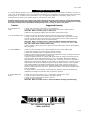
Install finial cap and glass to fitter body. Install
finial nut and tighten.
21
Plug ballast into the fluorescent tube.
18
Carefully place fluorescent lamp into clips on
fan. (see insert)
19
Install glass bowl.
20
1590-CUL-ENG
Install twin circular fluorescent tube to fan.
17
Install 9v battery by removing battery
cover on back of transmitter and connecting
to terminals and re-install cover.
FAN SPEED Depress "low" for low speed,
"med" for medium or "hi" for high. To turn
fan off press "fan/off"
LIGHT DIMMER To turn light on, press light
dimmer once quickly. To turn off press
once quickly while the light is on. To dim
light hold down button "light dimmer". The
light will cycle from bright to dim to bright
until button is released. Light will maintain
last setting if turned off.
FORWARD REVERSE Press Forward/
Reverse button. Fan will stop and blades
will reverse directions.
22
Battery com-
partment
Light control
button
Fan on/off
Foward/reve
rse button
Fan speed
controls

1590-CUL-ENG
HC-807
1.Check main and branch circuit fuses or circuit breakers.
2.Check line wire connections to fan and switch wire connections in switch housing.
CAUTION: Make sure main power is turned off.
3.Make sure that shipping stabilizer tabs have been removed from motor.
1.Check to make sure all screws in motor housing are snug (not over tightened).
2.Check to make sure the screws which attach the fan blade holder to the motor are tight.
3.Check to make sure wire nut connectors in switch housing are not rattling against each
other or against the interior wall of the switch housing.
CAUTION: Make sure main power is turned off before entering switch housing.
4.Some fan motors are sensitive to signals from Solid State variable speed controls. DO
NOT USE a Solid State variable speed control.
5.Allow "break-in" period of 24 hours. Most noises associated with a new fan will disappear
after this period.
1.Make sure that the ridge of the canopy engages the notch in the downrod ball.
2.Check that all blades are screwed firmly into blade holders.
3.Check that all blade holders are tightened securely to motor.
4.Make sure that canopy and mounting bracket are tightened securely to ceiling junction box
and junction box is mounted firmly to ceiling joist.
5.Most fan wobble problems are caused when blade levels are unequal. Check this level by
selecting a point on the ceiling above the tip of one of the blades. Measure this distance
from blade tip to ceilng. Keeping measure within 1/8", rotate the fan until the next blade is
positioned for measurement. Repeat for each blade. If all blade levels are not equal, you can
adjust blade levels by the following procedure. To adjust a blade tip down, insert a washer
(not supplied) between the blade and blade holder at the screw closest to the motor. To
adjust a blade tip up, insert washer (not supplied) between the blade and blade holder at
the two screws farthest from the motor. Reverse the position of the washer if blades mount
from top of blade.
6.If blade wobble is still noticeable, interchanging two adjacent (side by side) blades can
redistribute the weight and possibly result in smoother operation.
1.Check wire from fan to make sure it is connected to hot wire from house.
2.Check for loose or disconnected wires in fan switch housing.
3.Check for loose or disconnected wires in light kit.
4.Check for faulty light bulbs.
CAUTION: Make sure main power is turned off before entering switch housing.
2. If fan sounds noisy:
1. If fan does not
start:
3. If fan wobbles:
4. If light does not
work:
Trouble Shooting
If you have difficulty operating your new ceiling fan, it may be the result of incorrect assembly, installation, or wiring. In
some cases, these installation errors may be mistaken for defects. If you experience any faults, please check this Trouble
Shooting Chart. If a problem cannot be remedied, or you are experiencing difficulty in installation, please call our
Customer Service Center at the number printed on your parts list insert sheet.
Warning: Before servicing or cleaning unit, Switch power off at Service panel and lock service disconnecting
means to prevent power from being switched on accidentally. When the service disconnecting means cannot
be locked, securely fasten a prominent warning device, such as a tag, to the service panel.
Trouble
Suggested Remedy
For Technical Support Call:
(866) 449-2821
-
 1
1
-
 2
2
-
 3
3
-
 4
4
-
 5
5


Sea gull lighting 15082B-965 Installation guide
- Category
- Household fans
- Type
- Installation guide
- This manual is also suitable for
Ask a question and I''ll find the answer in the document
Finding information in a document is now easier with AI
Related papers

Other documents
-
 Monte Carlo Fan Company 5PR52 Series Owner's manual
-
 Monte Carlo Fan Company 5DS44 Series User manual
-
 Monte Carlo Fan Company 5DS44 Series User manual
-
 Monte Carlo Fan Company 5CZ52 Series User manual
-
 Monte Carlo Fan Company 5DS44 Series User manual
-
 Monte Carlo Fan Company 5VL52 User manual
-
 Monte Carlo Fan Company WEATHERFORD Series Owner's manual
-
 Monte Carlo Fan Company 5WFXX User manual
-
Monte Carlo Fan Company Crystoria Owner's manual
-
Design House 157347-BN Installation guide


